1
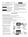
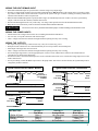
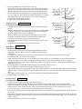
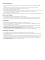
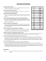
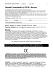
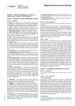
INSTALLATION/OPERATING INSTRUCTIONS
BCP-3
Hot Water Reset Control
For up to 3 Boilers
How the BCP-3 operates...
The BCP-3 establishes ambient comfort by varying the temperature of the heating system's circulating hot water in response to
changes in the outdoor temperature. In addition, it provides an
outdoor temperature based start/stop and system pump control
for systems with less than 3 boilers.
even 4 degrees in order to gain the desired comfort level. This
is known as the reset ratio. The middle chart shows the wide
range of reset ratios available for the BCP-3.
The installer fits the BCP-3 to a specific building by adjusting
the reset ratio curve. With a curve of 4 (2:1 reset ratio) a 2degree change in outdoor temperature will change the circulating hot water temperature by 1 degree; at an 11 curve (1:3 reset
ratio) an outdoor change of 1 degree will change the water
temperature by 3 degrees. Most
buildings with baseboard
1:2
1:1.5
radiation require a curve of 6, 7,
10
9
or 8. Radiant heat applications
usually require a lower curve.
8 1:1.25
Because of many physical
characteristics, and the type of
radiation, ie. baseboard or
radiant, heat loss varies. In
one building, a 1-degree
temperature change outdoors
may require a change of 1
degree in heating water
temperature; for another it may
require a change of 2, 3, or
Water Temperature (in °F)
Two sensors are used, one to monitor the outdoor temperature,
and one to monitor the temperature of the circulating hot water
in the heating system. When the outdoor temperature falls to
the outdoor starter setting, the
heating system is activated
1:4 1:3
and the hot water temperature
is increased proportionally to
12 11
220
meet the need for more heat.
210
Should it get warmer outdoors,
the hot water temperature is
200
automatically lowered by the
190
control. If the outdoor
temperature continues to rise
180
to the outdoor starter setting
170
then the heating system is
turned off.
7 1:1
6 1.25:1
160
5 1.5:1
150
4 2:1
140
120
3 3:1
2 4:1
110
1 8:1
130
100
70
60
50
40
30
20
10
0
An optional external heat
demand input can be connected
to the BCP-3 This can be
connected to a new or existing
thermostat or switch to shut the
heating system down when the
thermostat is satisfied.
The BCP-3 can control all the
following types of systems: one
boiler with system pump, one
lo/hi fire boiler with system
pump, two boilers with system
pump, or three boilers (system
pump output must be provided
separately).
-10 -20
Outdoor Temperature (in °F)
W A R N I N G This manual must only be used by a qualified heating installer/service
technician. Failure to comply could result in severe personal injury, death or
substantial property damage.
Part Number 550-141-696/1200
1
WARNING
DEFINITIONS
The Weil-McLain BCP-3 is strictly an operating control;
do not use as limit(s) or safety control(s). Each boiler
must have its own certified limit and safety controls as
required by codes. These controls are the responsibility
of the installing contractor. He must verify proper
operation and correct any safety problems before
installing the BCP-3.
The following defined terms are used throughout this
manual to bring attention to the presence of hazards
of various risk levels, or to important information
concerning the life of the product.
W A R N I N G Indicates presence of hazard
which can cause severe personal
injury, death or substantial
property damage if ignored.
Failure to follow all instructions in proper order can
cause severe personal injury, death or substantial
property damage. Read all instructions before installing
Weil-McLain BCP-3.
C A U T I O N Indicates presence of hazard
which will or can cause minor
personal injury or property
damage if ignored.
INSTALLATION
MOUNTING THE CONTROLLER
•
•
•
•
•
The BCP-3 is designed to mount on a standard 1900 (4”x4”) electrical box (not supplied).
If panel mounting, or if additional room is needed for wiring, an extension skirt is available.
Locate the BCP-3 in a convenient location near the unit to be controlled.
Mount the unit away from excessive heat or cold. Ambient operating temperature is from 20 to 120°F.
After completing all the wiring connections (see below) use the two screws provided to mount the BCP-3 to the 1900 box.
INSTALL THE HEATING SYSTEM SENSOR
• The BCP-3 heating system sensor is designed to be installed in a 3/8" ID well.
• Locate the sensor in the common header, where it will register the output of all the boiler stages. If the sensor can not read the
output of all the stages, the control will not be able to sequence properly.
• The sensor wires can be extended up to 500’ by splicing with 18 gauge shielded wire.
• Do not run sensor wire in conduit with line voltage.
• The sensor has no polarity. Connect either
sensor wire to the front terminal marked SYS.
Output
• Connect the other sensor wire and the shield
3
(where needed) to a front terminal marked
BLACK
Output
COM.
2
ORANGE
BCP-3
INSTALL THE OUTDOOR SENSOR
• Locate the sensor in the shade on the north
side of the building.
• Be sure the location is away from doors,
windows, exhaust fans, vents, or other
possible heat sources.
• The sensor should be mounted at least 4
inches away from the building wall and
approximately 10 feet above ground level.
• The sensor wires can be extended up to 500’ by
splicing with 18 gauge shielded wire.
• Do not run sensor wire in conduit with line
voltage.
• The sensor has no polarity. Connect either
sensor wire to the front terminal marked OUT.
• Connect the other sensor wire and the shield
(where needed) to a front terminal marked
COM.
OUTPUT
RED
= Computed Temp
= Outdoor Temp
= Fine Tune
= Outdoor Starter
= Reset Ratio
SELECT SETTING
DOWN
= Reaction Time
SYS COM OUT COM
Heating System
Sensor
Outdoor Sensor
Output
1
UP
BLUE
120VAC
Power
HEAT
DEMAND
Heat Demand Input
Dry Contact Only
NOTE:
COM terminals
are connected
internally and are
interchangeable.
2
WIRING THE HEAT DEMAND INPUT
• If the HEAT DEMAND inputs are open, the BCP-3 will not energize any output stages.
• The BCP-3 is shipped with a jumper across the HEAT DEMAND inputs. DO NOT remove this jumper unless you replace it with a
dry contact switch which is closed when heat is required in the system. This type of contact is usually provided by a thermostat
which activates the BCP-3 when it requires heat.
• When the HEAT DEMAND inputs are opened, all boiler stages are immediately turned off. If there is an active System Pump
output, it will run on for three minutes, and then also turn off.
• The Heat Demand signal must be a dry contact only. No voltage can be placed across the HEAT DEMAND terminals.
• Bring the two wires from the dry contact to the front terminals marked HEAT DEMAND.
Do not remove the factory installed Heat Demand jumper without installing a Heat Demand switch.
CAUTION
WIRING THE POWER INPUTS
• Attach 120VAC line voltage to the two blue wires extending from the back of the BCP-3.
• Use wire nuts, or wrap the connections with electrical tape.
• Class 1 voltages must enter the enclosure through a different opening from any Class 2 wiring.
WIRING THE OUTPUTS
•
•
•
•
•
The output wires provide a dry contact closure only. They do not source any power.
Each pair of same colored wires are connected internally to a N.O relay which is rated at 8 Amp max.
Total output of all stages must not exceed 15A.
Class 1 voltages must enter the enclosure through a different opening from any Class 2 wiring.
For on/off (single stage) boilers, wire the appropriate pair of wires in series with the boiler’s limit circuit or thermostat wire
terminals (TT) as shown in the chart below.
• For lo/hi fire boilers, connect the Red output wires in series with the boiler's limit circuit. Connect the Orange output wires to the
Hi fire control circuit.
• For a System Pump, connect the Black output wires to the pump starter. Note if there are three boilers, the System Pump must be
energized by another controller.
Typical Limit Circuit for ON/OFF Boilers
Wire
Pair
Internal
N.O. Relay
Limit Circuit or
TT if available
on boiler
Typical Limit Circuit for Lo/Hi Boilers
Red
Internal
N.O. Relay
Limit
Circuit
Red
Refer to Specific Boiler Wiring Diagram
Orange
Internal
N.O. Relay
System Pump
Orange
Black
Internal
N.O. Relay
Hi Fire
Circuit
Refer to Specific Boiler Wiring Diagram
To Pump
Starter
Black
SYTEM TYPE
1 Boiler & Pump
2 Boilers & Pump
3 Boilers
1 Lo/Hi Boiler & Pump
OUTPUT 1
Red Wires
Boiler 1
Boiler 1
Boiler 1
Lo Fire Boiler 1
OUTPUT 2
Orange Wires
Not connected
Boiler 2
Boiler 2
Hi Fire Boiler 1
OUTPUT 3
Black Wires
System Pump
System Pump
Boiler 3
System Pump
3
INITIAL CONTROL START-UP
• Whenever the BCP-3 is powered up, it will display the software version number and then the current operating parameters. Each
display will remain on the screen approximately 5 seconds. If the parameters are correct, there is no need to make any adjustments.
• Once the parameters have been set for a particular application, they will be retained in memory and will not need to be reset.
• Note that if you do change an operating parameter, you will need to reset all the settings (shown on chart on next page).
• An operating parameter can only be changed when it is being displayed in the start-up sequence. To restart the sequence it is
necessary to remove power to the BCP-3 and then power it again.
• Set the operating parameters as described in sequence below:
°F or °C - Fahrenheit or Celsius Temperature Operation Default is °F
• If the display shows °F then the BCP-3 will operate in Fahrenheit degrees.
• If the display shows °C then the BCP-3 will operate in Celsius degrees.
• To change the temperature operation, hold down the center button while pushing either the UP or DOWN button to toggle
between the displays of °F and °C.
• When the correct temperature operation is selected, release the buttons and wait approximately 5 seconds.
b_1, 2, 3, or 4 - Output selection Default is b_3
• If the display shows b_1 then the BCP-3 will control 1 On/Off Boiler and a System Pump.
• If the display shows b_2 then the BCP-3 will control 2 On/Off Boilers and a System Pump.
• If the display shows b_3 then the BCP-3 will control 3 On/Off Boilers.
• If the display shows b_4 then the BCP-3 will control 1 Lo/Hi Boiler and a System Pump.
• To change the boiler output selection, hold down the center button while pushing either the UP or DOWN button to toggle
between the displays the boiler outputs.
• When the correct boiler output is selected, release the buttons and wait approximately 5 seconds.
Minimum Water Temperature Default is 140°F
• The display will next show the minimum water temperature setting. The BCP-3 can not compute a calculated water temperature
below this setting, and can not have a set point value below this.
• DO NOT lower this below the default setting of 140°F without contacting your Weil- McLain representative.
• To change the minimum water temperature, hold down the center button while pushing either the UP button to increase the value,
or the DOWN button to decrease the value.
• When the desired minimum water temperature is selected, release the buttons and wait approximately 5 seconds.
DEFAULT SETTINGS
Settings shown in instructions have been selected by Weil-McLain and will provide proper operation for many
installations.
• The BCP-3 comes equipped with default settings which are a good starting point for most installations.
• After the start-up routine has completed, the display will show the system water temperature.
• To display the other settings (see chart next page), repeatedly press the center PRESS TO READ button.
• A setting can only be adjusted when it is being displayed.
• Use the UP and DOWN buttons to adjust the setting.
• The display will always revert back to the actual system water temperature after 30 seconds.
• The default Fine Tune is 0°. This means the system target temperature will be 100°F at an outdoor temperature of 70°F as shown
on the reset curves on the front page.
• The default Outdoor Starter setting is 60°F. When the outdoor temperature is above the Outdoor Starter setting, the BCP-3 will
not give heat.
• The default Reset Ratio is curve 7 or 1:1 (see chart
on first page). This ratio should be a good
Default Display:
starting point for applications with baseboard or
System Water
radiators. If the application has radiant heat, a
Temperature
lower numbered reset ratio curve should be
selected.
OUTPUT
• The default Reaction Time is 5 minutes. This
makes the minimum run time for any stage 2 1/2 (or
UP
Press and
Press to scroll
half the reaction time).
SELECT SETTING
hold to adjust
through settings
DOWN
4
OPERATION
DISPLAY SETTINGS
Calculated water temperature
Center button pressed once
• This is the water temperature the BCP-3 will stage units to hold. It is based on outdoor temperature and the Fine Tune and Reset
Ratio values (described in the following sections).
• The Calculated water temperature can not be less than the Minimum Water temperature setting (see opposite page).
• If either sensor is reading a fault condition, all stages will immediately turn on. The Calculated display will show ON to indicate
this condition.
• If the outdoor temperature is above the Outdoor Starter setting, the BCP-3 will not activate stages. The Calculated display will
show OFF to indicate this condition.
• The BCP-3 will either add stages, subtract stages, or maintain the same number of stages to hold the system temperature around
the Calculated temperature.
• The Calculated temperature is the average temperature the BCP-3 will maintain. The system can be expected to fluctuate above
and below this temperature. The size of the fluctuation depends on the number of stages, the size of each stage, the system load,
and the Reaction Time.
• The Calculated temperature is based on all the settings described above. The temperature value can not be changed by pressing
the UP or DOWN button while it is displayed.
Fine Tune
Default is 0°
Center button pressed three times
• The Fine Tune value moves the starting point of the Reset Ratio curves (see charts on the next page).
• Therefore, any change made to the Fine Tune will immediately change the value of the Calculated water temperature by the same
amount.
• For example, if the Calculated water temperature were 150°F based on the specific outdoor temperature and Reset Ratio, then
increasing the Fine Tune from 0°F to 10°F would increase the Calculated water temperature to 160°F.
DISPLAY CHART AND ADJUSTMENTS
Press SELECT
Button
DISPLAY
Once *
Computed
Twice *
Outdoor Temp
3 Times
4 Times
5 Times
6 Times
7 Times *
Press and hold either the UP or DOWN button to adjust the value
This is the water temperature the BCP-3 will control boilers to hold. It is based on
the outdoor temperature, reset ratio, and the fine tune value. If ON is shown, there
is a sensor fault. If OFF is shown, there is no call for heat.
This is the outdoor sensor temperature value.
The Fine Tune moves the reset curves vertically up or down. For example,
changing the offset from 0 to -10 will decrease the water temperature 10°
regardless of outdoor temperature or the reset curve selected. The Fine Tune is
adjustable from -40 to 40°F.
Fine Tune
Outdoor
Starter
Reset Ratio
When the outdoor temperature falls below the Outdoor Starter setting, the BCP-3 will
give heat. When the outdoor temperature is above the Outdoor Starter, the
Calculated value will be OFF and no stages will be activated. The Outdoor Starter
is adjustable from 40 to 100°F
The Reset Ratio controls the amount of heat which enters the heating system based
on the outdoor temperature. A higher numbered Reset Ratio will result in a higher
Calculated water temperature. See the chart on the first page for the reset curves.
The Reset Ratio is adjustable from 1 to 12.
Reaction Time
The Reaction Time controls the minimum run time for a stage. It is adjustable from
half a minute (0.5) to 8.0 minutes.
Default
The BCP-3 returns to the default display of actual system water temperature.
* These values can not be adjusted
5
Default is 60°F
Center button pressed four times
• The Outdoor Starter sets at what outdoor temperature the BCP-3 will begin
heating.
• When the outdoor temperature is above the Outdoor Starter setting, the BCP3 will not activate stages. The Calculated water temperature will read OFF.
• The Outdoor Starter has a built in 2°F differential.
• When the outdoor temperature drops below the Outdoor Starter setting
minus the 2°F differential, the BCP-3 will compute the Calculated water
temperature and sequence stages to hold that temperature.
• If the building is too cold before the system starts, raise the Outdoor Starter
temperature.
• The Outdoor Starter temperature can be set from 40 to 100°F.
Reset Ratio
Default is 7
With a -20° Fine
Tune, the ratio
curves begin at
80° Water
Temperature.
Water Temperature
1:1
120
110
4:1
70
60
50
40
Outdoor Temperature
1:3
110
1:1
100
90
80
With a +20° Fine
Tune, the ratio
curves begin at
120° Water
Temperature.
1:3
130
100
Water Temperature
Outdoor Starter
With a 0° Fine
Tune, the ratio
curves begin at
100° Water
Temperature.
Water Temperature
• In a new installation, start with a Fine Tune value of 0°.
• Adjust the Fine Tune value in mild weather. If the ambient indoor temperatures are warm in the warm weather, decrease the Fine Tune. If the ambient
building temperatures are cold in the mild weather, increase the Fine Tune.
• The rule of thumb for baseboard radiation is to change the Fine Tune by 4°
for every degree you wish to change the building temperatures. For radiant
heat applications, change the Fine Tune by 1° or 2° for every degree you
wish to change the building temperature.
• The Fine Tune can be set from -40 to 40°F.
4:1
70
60
50
40
Outdoor Temperature
150
1:3
1:1
140
130
120
4:1
70
60
50
40
Outdoor Temperature
Center button pressed five times
• The Reset Ratio controls how much heat will be added based on outdoor
temperature. The Reset Ratios are shown as Outdoor Temperature:Water
Temperature.
• A 1:1 Reset Ratio signifies for each degree it gets colder outside, the Calculated water temperature will raise 1 degree.
• The other Reset Ratios are shown on the first page.
• The Reset Ratio curves start at 70°F. At 70°F the BCP-3 will require 100°F water. Note that this is not the point where the BCP-3
will begin giving heat. That point is determined by the Outdoor Starter. Also note this starting point can be changed by
adjusting the Fine Tune as shown above. Finally, the Calculated water temperature can never be less than the Minimum Water
temperature (see pg. 4).
• For new installations with standard baseboard heating, begin with a Reset Ratio curve of 7.
• For new installations with radiant heat, begin with a Reset Ratio curve of 4 or 5.
• Adjust the Reset Ratio value in cold weather. If the ambient indoor temperatures are cold in the cold weather, pick the next higher
Reset Ratio (that is, go from 7 to 8). If the ambient building temperatures are warm in the cold weather, pick the next lower Reset
Ratio.
• After adjusting the Reset Ratio curve, wait at least 24 hours before making another adjustment.
• The Reset Ratio can be set from 1 to 12.
Reaction Time
Default 2.0
Center button pressed six times
• The Reaction Time controls the minimum run time for any stage.
• When a boiler stage has been added, that stage can not be turned off until at least half the Reaction Time has elapsed.
• The Reaction Time must be at least as long as the time it takes for a newly activated stage to start affecting the system. If the
Reaction Time is shorter than this, the BCP-3 may activate additional stages before it can see the impact of each stage.
• For cast iron boilers, it is recommended to start with a Reaction Time of 5.0 minutes.
• If the system temperature tends to fluctuate rapidly above and below the Calculated water temperature, the Reaction Time may be
set too short.
• If the system temperature tends to remain always below the Calculated water temperature, the Reaction Time may be set too long.
• When making a change to the Reaction Time, wait at least 5 reaction times before making another change. The system will need
time to settle out.
• The Reaction Time can be set from 0.5 to 8.0 minutes.
6
LEAD STAGE ROTATION
• For the single boiler and lo/hi boiler operating mode, when heat is required, the first stage brought on is Output 1 (see output
chart pg. 3).
• For the 2 and 3 boiler operating modes, the lead stage will rotate among the boilers to promote even wear on each unit.
• The Lead Stage will always be the first stage brought on when there is a call for output.
• As more output is needed, additional stages are added.
• When less output is needed, the additional stages are turned off in the reverse order of how they were added. For instance, if the
stages were added in the sequence 1, 2, and 3, then they will be turned off in the sequence 3, 2, and finally 1.
• On power-up, the lead boiler will always be Output 1.
• The Lead Stage will rotate every 24 hours (either between Output 1 and 2 for 2 boilers, or between Output 1, 2 and 3 for 3 boilers).
OUTPUT LIGHT DISPLAY
• The red LED marked OUTPUT indicates when the BCP-3 is in the heating mode.
• The red LED will be off when the outdoor temperature is above the Outdoor Starter, or when the HEAT DEMAND input is open.
• When the outdoor temperature is below the Outdoor Starter, and the HEAT DEMAND input is closed, the red LED will be on.
HEAT DEMAND
• When the HEAT DEMAND input terminals are open, the BCP-3 will not energize any stages.
• The BCP-3 comes equipped with a factory installed jumper across the HEAT DEMAND terminals. DO NOT remove this jumper
unless it is being replaced by a dry contact switch.
• This input would typically be provided by a thermostat. When the thermostat is satisfied, there is no need for heat. When the
thermostat requires heat, the BCP-3 will activate and stage the Outputs to hold the required set point.
• This input can also be used as a remote stop/start for the BCP-3.
• When the HEAT DEMAND terminals are first opened, all active boiler outputs will immediately turned off. However, the System
Pump output (not available in the 3 boiler operating mode) will continue to run on for 3 minutes before turning off.
SYSTEM PUMP OPERATION
• The System Pump output is design to continuously circulate the heating water whenever heat is required.
• The System Pump relay will energize whenever the outdoor temperature is below the Outdoor Starter temperature and the HEAT
DEMAND input is closed.
• When either the outdoor temperature rises above the Outdoor Starter, or the HEAT DEMAND input is opened, the System Pump
will run on for 3 more minutes. This removes heat from any boiler stages which were active and circulates it around the system.
• If the System Pump output has not been activated for 7 days (as might occur in the summer), the relay will be energized for 15
seconds to exercise the pump.
• The System Pump output not available in the 3 boiler operation mode.
7
TROUBLESHOOTING
No Display or Display of 888
Check the power to the BCP-3. The BCP-3 requires 120VAC power to the blue wires.
Turn the power off and back on to restore display.
Actual or Outdoor Display shows OPN
Check that the wires from the sensor are continuous to the BCP-3. Then follow the
procedure for Incorrect Temperature Display.
Actual or Outdoor Display shows SHT
The BCP-3 sees a short across the input terminals. Remove the wires from the input
terminals. The display should change to read OPN. If it doesn’t, the BCP-3 may be
damaged.
Actual or Outdoor Display shows an Incorrect Temperature Display
Remove the wires from the input terminals. The display should change to read OPN.
If it doesn’t, the BCP-3 may be damaged. Take an ohm reading across the detached
sensor wires. The ohm reading should correspond to the chart at right. If it doesn’t,
the sensor may be damaged.
No Heat - No Outputs - Output Light OFF
Check the outdoor temperature and Outdoor Starter readings. If the outdoor temperature is above the Outdoor Starter, the BCP-3 will not give heat. Then check the HEAT
DEMAND terminals. If the HEAT DEMAND terminals are not jumped together, the
BCP-3 will not give heat.
No Heat - No Outputs - Output Light ON - 3 Boiler Mode
Check if the actual water temperature is above the Calculated water temperature. If it
is, wait until the actual water temperature falls or increase the Fine Tune value until
the Calculated water temperature is above the actual. Stages should begin to fire.
TEMPERATURE
(in degrees F)
0
10
20
25
30
35
40
45
50
55
60
70
80
90
100
110
120
130
140
150
160
170
180
190
200
VALUE
(in Ohms)
42683
31215
23089
19939
17264
14985
13040
11374
9944
8714
7653
5941
4649
3667
2914
2332
1879
1524
1243
1021
842
699
583
489
412
No Heat - No Outputs - Output Light ON - All other modes
Remove any connections to the Black System Pump wires. Test for continuity across the System Pump output. If the wires are
continuous, the BCP-3 is calling for the System Pump to run. Check the pump to determine why it is not circulating.
One or more of the Boiler Stages does not fire - Lo/Hi Fire mode
If the red OUTPUT light is not on, no stages should be firing. If the actual water temperature is above the Calculated water
temperature, no stages should be firing. Otherwise, remove all connections to the Red and the Orange output wires and test for
continuity. If the Red wires are continuous, the Lo fire stage should have been running. If it wasn't, check the boiler. It may be
off on a boiler limit. If the Red and the Orange wires are continuous, and the Lo stage was firing, check the boiler to determine
the fault with the Hi fire circuit.
One or more of the Boiler Stages does not fire - All other boiler modes
If the red OUTPUT light is not on, no stages should be firing. If the actual water temperature is above the Calculated water
temperature, no stages should be firing. Otherwise, remember the lead stage will rotate every 24 hours. If one boiler is sufficient
to hold the actual temperature at or above the Calculated water temperature, then the other boiler stages will not be active until
the lead changes. If no boilers are firing, remove all connections to the output wires and check for continuity. If any set of wires
were continuous, that boiler should have been firing. Check that boiler.
REPAIR PARTS
389-900-177
3/8" Brass sensor with plastic wall mount clip. This sensor can be used for either system temperature or outdoor
temperature
8