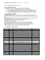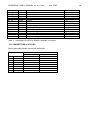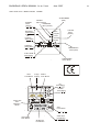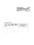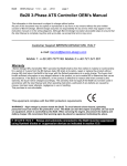
1
Be23A/Be46 OEM’s MANUAL 1.x.xx, 2.x.xx
June 2007
1
Genset Controller Be46 OEM’s Manual
The information in this document is subject to change without notice.
No part of this document may be copied or reproduced in any form or any means without the prior written
consent of Bernini Design company. Bernini Design assumes no responsibility for any errors which may
appear in this instruction manual or in the wiring diagrams.
Although Bernini Design has taken all possible steps to ensure that the User Manual is complete, bug free and
up-to-date, we accept that errors may occur. If you encounter problems with this instruction manual, please
complete this form and send it back to us.
FAX Message (++39 0386 31657), From:_____________________________________________________
Name:_____________Company:_____________________Tel/Fax:________________________________
I would like to report the following error:
________________________________________________________________________________________
Bernini Design srl - Italy ++39 0386-31445 (fax 31657)
Customer Support e-mail: [email protected] mobile: ++39 335 70 77 148
Warranty
Bernini Design SRL (hereinafter "BD") warrants that Be46 shall be free from defect in material or
workmanship for a period of 3 years from the BD delivery date. BD shall, at its option, repair or replace the
product without charge. BD shall return the Be46 to the buyer with the Default parameters at no extra charge.
The buyer shall furnish sufficient information on any alleged defects in the product so as to enable BD to
determine their cause and existence. If the Be46 is not defective, or the product is defective for reason other
than covered by this warranty, the buyer will be charged accordingly. This warranty shall not apply if the Be46
has not been used in accordance with the User Manual and other operating instruction, particularly if any
defects are caused by misuse, improper repair attempts, negligence in use or handling.
This purchase is non-refundable.
This equipment complies with the EMC protection requirements
!! W A R N I N G !! Relays and solenoids connected to the Be46 must be
suppressed using flywell diodes or suppression devices (e.g. RC networks).
WARNING!! High voltage is present inside the Be46. To avoid electric-shock hazard, operating
personnel must not remove the protective cover. Do not disconnect the grounding connection. The
Be46 can start the engine at anytime. Do not work on equipment, which is controlled by the Be46.
When servicing the engine, disconnect the battery and battery charger. We recommend that warning
signs be placed on equipment indicating the above.
DANGER : THE BE46 DOES NOT GENERATE A WARNING OR AUDIBLE SIGNAL
PRIOR TO INITIATING THE STARTING PROCEEDINGS. DO NOT WORK ON
EQUIPMENT WHICH IS CONTROLLED BY THE BE46 UNIT. WE RECOMMEND THAT
YOU PLACE WARNING SIGNS ON THE MAIN PARTS OF THE GENERATING-SET.
Be23A/Be46 OEM’s MANUAL 1.x.xx, 2.x.xx
June 2007
Index:
Alarms...............................6.0
Alarm Menu ......................5.05
Alarm [Horn] control ........5.02A
Automatic Mains Failure ..4.04
Automatic .........................4.0
Auxiliary alarm .................6.15
Battery, Alarms ................6.04
Belt break [bELt] ..............6.13
Calibration.........................12.0
Characteristics..................7.0
Charger Alternator............7.10
Contactor ..........................4.04, 3.04
Connectors, Plugs ...........14.1
Crank timing .....................6.03,5.02F
Current Transformer ........7.03, 5.02B
Current, setting ................5.02B
Cooling down time ...........5.02A [CooL]
Defaults.............................5.07
Digital input ......................7.04
Dimensions .......................15.0
Display ..............................5.0
Display Messages ............5.0, 5.01
Error codes .......................5.05,
[Err] message ...................6.16, 5.06
Engine Running ...............7.07
External Stop (Input 3) .....4.06, 6.05
Fail to Start [F Cr] .............6.03
Front Panel .......................16.0
Frequency .........................5.04, 6.07
Fuel Level .........................6.08, 6.09, 7.09
Fuel Solenoid control ......14.0, (JF25)
Generator Voltage ............7.02
Generator Frequency .......5.04, 6.07
Generator Failure .............6.14
Glow Plugs [HEAt] ...........[HEat] 5.02A
Hi-U, Over Voltage............5.05, 5.02B
Hour Meter ........................5.04, 12.01
Inputs ................................7.04, 7.06
Input 4 control ..................5.02F
LED, LEDs ........................6.0, 16.0
Lamp Test .........................1.01B
Lo-U, Under Voltage.........5.05, 6.12
Low Battery voltage .........6.04
Mains Failure ....................4.04
Measurements ..................5.0, 12.0
Memory erase ...................6.17
Messages (Display) ..........5.0
Manual ..............................3.0
Oil pressure ....................... 6.01, 5.02H
Output, Outputs ................. 7.01
Operating modes ............... 3.0, 4.0
Overload [Hi I] .................... 5.02B
Over Frequency [HiFr] ....... 5.02C, 6.07
Over Voltage [HI-U] ............ 6.12, 5.02B
Parameters ......................... 5.02A-5.02L
Parameters reading ........... 5.02
Pick Up ............................... 5.02C, 7.08
Programming ........... 5.06, 5.08
Pump control...................... 4.04
Power Supply ..................... 7.00
Power, setting .................... 6.10
Power Menu........................ 5.03
Push buttons ...................... 16.0, 2.01
Reset (OFF) ........................ 3.05
Rest time [rESt] .................. 5.02F
Serial interface ................... 10.0
Settings (Parameters) ........ 5.02
Specification ...................... 7.00
Speed, alarms .................... 6.06, 5.02C
Software upgrade............... 17.0
Start [StA ] .......................... 3.02, 4.03
Start Attempts [Att ] ........... 17.0, v4.00
Starting Failure................... 6.03
Static Output ...................... 7.01
Stop, Stop solenoid ........... 3.03, 4.06, 5.02A
Timers ................................. 5.02
Terminal description .......... 14.0
Temperature ....................... 5.02D, 6.02, 7.06
Test, Remote Test ............. 4.03
Transformer, Current ......... 5.02B[Ct.r]
Trouble-shotting ................ 11.00
Under Voltage Lo-U ........... 5.02B, 6.12
Under Frequency .............. 5.02C, 6.07
Voltage................................ 6.12, 7.02
Warm-Up time .................... 5.02A
Wiring ................................. 9.0, 15.0
2
Be23A/Be46 OEM’s MANUAL 1.x.xx, 2.x.xx
June 2007
Be23A/Be46 OEM’s INSTRUCTION MANUAL
Important Note: because of a continuous product improvement policy, the information in
this instruction manual is subject to change without notice.
1.00 SETUP PROCEDURES .................................................... page 5
1.01 Initial Setting ..................................................... page 5
1.02 Wiring Installation Guidelines ........................... page 5
2.00 USER INTERFACE ............................................................ page 6
2.01 Display and Push Buttons................................. page 6
2.02 LED indicators .................................................. page 6
3.00 'MANUAL' OPERATING INSTRUCTIONS ......................... page 6
3.01 Be46 Initial Set Up ............................................. page 6
3.02 Manual START .................................................. page 6
3.03 Manual STOP ................................................... page 7
3.04 Load Control ...................................................... page 7
3.05 ‘OFF’ Operating Mode ....................................... page 7
4.00 'AUTO' OPERATING INSTRUCTIONS............................... page 7
4.01 Be46 Set Up .................................................... page 7
4.02 AUTO Operating Mode Selection ..................... page 7
4.03 Using a Remote Start Feature .......................... page 8
4.04 Using the A.M.F. Input 2 ................................... page 8
4.05 Alarm Monitoring in ‘AUTO’ .............................. page 8
4.06 Stop the Generating-set in ‘AUTO’ ................... page 8
5.00 DISPLAY MENU FEATURES ............................................. page 9
5.01 ‘ENGINE’ menu ................................................ page 9
5.02 ‘PROGRAM’ menu ............................................ page 9
5.03 ‘POWER’ Menu ................................................. page 14
5.04 ‘V/A/Hz/h’ Menu ................................................. page 14
5.05 ‘ALARM’ Menu ................................................... page 14
**************************************************************************
5.06 Programming Instructions: page 15
5.07 Re-programming Default settings ..................... page 15
5.08 MEMORY initialization ...................................... page 15
***************************************************************************
6.00 ALARM DESCRIPTION ...................................................... page 16
6.01 Oil Pressure Warning and Shut Down .............. Page 16
6.02 Temperature Warning /Shut Down ................... Page 16
6.03 Fail to Start Shut Down ..................................... Page 16
3
Be23A/Be46 OEM’s MANUAL 1.x.xx, 2.x.xx
6.04
6.05
6.06
6.07
6.08
6.09
6.10
6.11
6.12
6.13
6.14
6.15
6.16
6.17
June 2007
Battery Voltage Warning ................................... Page 16
‘External Stop Input 3’ Shut Down .................... Page 17
Over Speed / Under Speed Shut Down ............ Page 17
Under/Over Frequency Shut Down ................... Page 17
Low Fuel Level Shut Down ............................... Page 17
Low Fuel Level Warning ................................... Page 17
Over Power 'kVA' Shut Down ........................... Page 17
Over Current Shut Down .................................. Page 18
Over/Under Voltage Shut Down ....................... Page 18
Belt Failure Shut Down ..................................... Page 18
Alternator Failure Shut Down ............................ Page 18
‘Auxiliary Alarm Input 4’ Shut Down .................. Page 18
Memory ‘Err’ Message ...................................... Page 18
Memory Erase procedure ................................. Page 18
7.00 GENERAL SPECIFICATIONS ............................................................. page 19
7.01 Static Output Characteristics ............................................. Page 19
7.02 Generator Voltage Input Characteristics ............................ Page 19
7.03 Current Transformer Input Characteristics......................... Page 19
7.04 Digital Input Characteristics ............................................... Page 20
7.05 Oil Pressure Analogue Input Characteristics ..................... Page 20
7.06 Temperature Analogue Input Characteristics .................... Page 20
7.07 Engine Running detect ...................................................... Page 20
7.08 Pick Up Input Characteristics............................................. Page 20
7.09 Fuel Level Analogue Input Characteristics ........................ Page 20
7.10 Alternator (Battery Charger) Monitoring ............................. page 20
8.00 Charger Alternator monitoring .......................................................... page 20
9.00 Wiring dagram .................................................................................... page 21
10.00 Serial interface and monitoring ....................................................... page 21
11.00 Troubleshooting ............................................................................... page 21
12.00 Measurement and calibration .......................................................... page 22
12.01 Hour meter resetting ........................................................................ page 23
13.00 Definition of terms ............................................................................ page 23
14.00 Terminal description ........................................................................ page 23
14.10 Connectors and plugs ..................................................................... page 24
15.00 Rear view and dimensions .............................................................. page 25
16.00 Front panel description .................................................................... page 26
17. 00 Software upgrades and notes ........................................................ page 27
WARNING:
This unit is not user serviceable and should be returned to Bernini-Design Company for
service and repair. Any alterations to the internal circuits will invalidate the warranty.
4
Be23A/Be46 OEM’s MANUAL 1.x.xx, 2.x.xx
June 2007
5
1.00 SETUP PROCEDURES
The following procedures provide an operational checkup, as a means of verifying the
operation of the Be46. The procedures 1.01 and 1.02 are reserved for qualified personnel
only. After these preliminary operations, the operator can use the Be46 as described in
sections 2.00 (MANUAL) and 3.00 (AUTO). The section 16.00 describes the Front Panel
details.
1.01 Initial Setting
WARNING: TO AVOID PERSONAL INJURY, THE FOLLOWING OPERATIONS ARE TO
BE CARRIED OUT BY QUALIFIED PERSONNEL ONLY.
a) - Initial condition: no terminals are connected and the engine is not running.
b) - Connect the supply plug (#33=plus to 12V battery system, #35 if a 24V battery system
is used, and #34 = minus) to the battery of the engine. The allowed voltage range to operate
the Be46 is from 6 Vdc to 36 Vdc. The battery minus must be grounded only at the side of
the engine. It is dangerous to ground the minus wire of the Be46 supply in multiple sites:
different ground potentials may destroy the Be46 unit. As soon as power is supplied, the
Be46 performs an internal test and turns on all LEDs and displays for 3 seconds.
The version of the internal software (for example [2.0.08]) appears temporarily on the
display. The message [12 =] or [24 =] indicates the size of the connected battery.
Any failure during the cycle will produce a permanent ‘[Err]’ message on the display (section
6.16). If no errors are detected, one decimal point will ultimately be displayed in the Least
Significant Digit (*Note).
c)- Operate the pushbuttons on the front panel to read the parameters and check the
settings (see Section 5.02). Program the parameter [M_o.t.] according to the specification
of the engine manufacturer (see section 5.02D)
* NOTE: according to the setting of the parameter [OPt.2], the Be46 can enter directly into 'MANUAL' or AUTO
operating mode (see section 5.02F parameter [OPt.2]).
1.02 Wiring Installation Guidelines
A) - Unplug the supply connector in order to turn off the Be46 unit.
B) - Before connecting the input terminals #17 to #23, make sure that all contact switches
are in the normal operational mode. Oil pressure input must be connected to a ‘closed
contact’ switch, and the rest of the terminals must be wired to a contact that matches the
programmed action (normally open/closed , section 5.02F)
C) - Test each output load before connecting the wires. As soon as you are sure that the
solenoids and relays are working properly, you may commence connecting terminal #25 to
#32.
CAUTION: The use of a suppression device on each relay is mandatory
D) - Connect the sender terminals #13 to #16 (check the resistance of the sensor with an
OHM-meter). The allowed range is up to 2000 OHM (5.02H).
E) - Connect the 'Alternator Control' terminal #8 to the W.L. and place a proper connection
for 12V (#8 and #9 to W.L./D+) or 24V (#7 and #8 to W.L./D+).
Be23A/Be46 OEM’s MANUAL 1.x.xx, 2.x.xx
June 2007
6
F) - Connect the Current Transformer to the #5 and #6 terminal inputs (the ‘S1’ terminal of
the C.T. must be grounded on C.T. side).
G) - Connect the pick-Up. In case of use of W, connect the RPM- to the plus of the battery.
H)- The last connection has to be the genertator connector plug (#N, #L1, #L2, #L3).
NOTE: Make sure that wire connections to a removable terminal block are securely
fastened, and that there are no wire strands exposed
I)- To operate the Be46, connect the 3-pole supply plug (#33, #34 and #35). The display will
show, in sequence, the software version in a 4-digit form [X.X.XX], and the detected battery
[12=]V (or [24 =]V). Finally, the Be46 enters the ‘OFF’/'MAN' or 'AUTO' operating mode
according to the parameter [oPt.2] (section 5.02F).
2.00 USER INTERFACE
2.01 Display and Push Buttons
The Be46 front panel features 8 push buttons (section 16.0) and 4-digit displays made of
7-segment LEDs. In ‘MANUAL’ and ‘AUTO’ operating modes, by means of the [^] or [v]
pushbuttons, it is possible to select one of the following menus: ‘Alarm’, ‘Program’,
‘Power’, ‘V/A/Hz/h’, ‘Engine’.
By means of the [<] and [>] pushbuttons, the user browses the menu contents. In ‘OFF’
operating mode, the Be46 allows memory programming (Sections 5.06 and 12.00).
2.02 LED indicators
The Be46 has coloured LEDs (Light Emission Diodes). The front panel has 6 ‘ALARM’ red
LEDs, 1 [AUTO-MAN] green LED, 4 ‘Menu Select’ yellow LEDs and one red LED indicating
that a message is avalaible in the ‘Warning’ menu.
The 6 red alarm LEDs indicate the following:
- Oil Pressure shut down (input JB-17)
- Engine Temperature shut down (input JB-21)
- Battery Voltage warning, High or Low (supply source JA33-34-35)
- Fuel Level warning and shut down (input JB-19)
- Emergency Stop shut down (input JB18)
- Over Speed shut down (Pick Up inputs JG10-11-12)
Section 6.0 describes the alarms in detail.
3.00 'MANUAL' OPERATING INSTRUCTIONS
NOTE: according to the setting of the parameter [OPt.2], the Be46 can enter directly into
'MANUAL' operating mode (see section 5.02F: [OPt.2]=[1[).
3.01 Be46 Initial Set Up (Be46 begins in 'OFF' operating mode if [OPt.2]=[0] see NOTE1)
- Push [START-ON] push button for at least 2 secs: the 'LAMP TEST' will take place. After
the test, the [AUTO-MAN] green LED will not illuminate indicating the ‘MANUAL’ operating
mode. The display menu will be automatically placed in 'Engine' mode, and displays 4
dashes to indicate a stand-by condition. Now the user can:
- put the Be46 in 'OFF' by means of the [STOP-OFF] pushbutton (section 3.05).
- put the Be46 in 'AUTO' by pushing [AUTO-MAN] pushbutton (see Section 4.02).
- START and STOP the set by using [START-ON] and [STOP-OFF] push buttons (see
sections 2.02, 2.03).
- browse the menus of the display (see Section 5.00).
NOTE1: the parameter [OPt.2] allows you to select the operating mode after the Power on
sequence (see section 5.02F).
Be23A/Be46 OEM’s MANUAL 1.x.xx, 2.x.xx
June 2007
7
3.02 Manual START (Be46 is already in 'MANUAL' operating mode)
-Push the [START] pushbutton until an engine start has been obtained. To enable this
cycle, the alarm memory must be empty. The alarms are indicated by means of red LEDs.
In order to clear the alarms, press the [STOP-OFF] pushbutton, and then repeat step 3.01
(see section 6.00). If a 'STOP cycle' is engaged, wait for the end of the ‘STOP’ timing, or
push the [STOP-OFF] pushbutton again in order to reset the Stop cycle.
The message ‘[Sta]’ is displayed in the 'Engine' menu during the Crank cycle.
The Be46 automatically detects the moment to disconnect the 'STARTER' as explained in
section 7.07.
The yellow LED ‘Engine’ flashes if one source of ‘Engine running’ signal is true. Further
action on the [START-ON] push button will be ignored. If the 'PREHEAT' function is
programmed, the ‘[HEAt]’ message appears on the display during the PREHEAT cycle. The
fuel solenoid is automatically disabled if the engine does not start properly within 20
seconds (e.g. the user has pushed the [START] pushbutton too quickly). In 'MANUAL'
operating mode, the 'UNDER FREQUENCY' and 'UNDER VOLTAGE' alarms are ignored.
3.03 Manual Stop
Push the [STOP-OFF] pushbutton (see section 16.0 for Front Panel details) until the
message ‘[StOP]’ appears on the ‘Engine’ menu display.
The FUEL SOLENOID (output #25) is disabled, and, at the same time, the 'STOP
SOLENOID' (output #31) energizes for the programmed time ([StOP] in Section 5.02A).
After the end of the 'STOP' cycle, pushing the [STOP-OFF] pushbutton will turn the Be46 to
'OFF' operating mode.
‘OFF’ operating mode is a low power condition indicated by means of a decimal point on the
right side of the display.
3.04 Load Control
In Manual mode, the electrical load is normally transferred to the Mains, independently of
the status of the Mains. If the contactors are not used, the user can connect the electrical
Load to the Generator, by means of a manually operated circuit breaker. In this case, the
'UNDER FREQUENCY' and 'UNDER VOLTAGE' protections are not operative (enabled
only in 'AUTO'). For this reason, it is better to use the ‘AUTO’ operating mode. In this way,
an external contactor protects the Load and the Generating-set in all conditions (output
#28).
3.05 ‘OFF’ Operating Mode
This mode is indicated by means of an illuminated dot on the right side of the display. This
mode is always obtained by pushing the [STOP-OFF] push button (section 16.0 for Front
Panel details).
4.00 AUTO OPERATING INSTRUCTIONS
NOTE: according to the setting of the parameter [OPt.2], the Be46 can enter directly into
'AUTOMATIC' operating mode (see section 5.02F: [OPt.2]=[2[).
4.01 Be46 Set Up (Be46 is in 'OFF' operating mode, [OPt.2]=[0])
Press the [START-ON] pushbutton (see section 16.0) for at least 2 secs: the 'LAMP TEST'
will take place, and, at the end, the LED 'AUTO/MAN' will no longer be illuminated
(‘MANUAL’ mode). The display menu will be automatically placed in 'Engine' mode to show
the operating messages.
Be23A/Be46 OEM’s MANUAL 1.x.xx, 2.x.xx
June 2007
8
4.02 AUTO Operating Mode Selection
Push [AUTO-MAN] for at least 1 sec (section 16.0 for Front Panel details). The green
LED, on the top of the push button, will illuminate as confirmation of the 'AUTO' mode. The
Starting and Stopping of the engine will depend on the status of the REMOTE START input
(#20), and the ‘AMF input 2’ (#22, programmable [n.o] or [n.c.]).
If one or more alarms are present, the Be46 inhibits the transition from ‘MAN’ to ’AUTO’. All
alarms have to be recognized and cleared before selecting the ‘AUTO’ operating mode. If
the alarm memory is not empty, the red ‘Alarm’ LED flashes slowly, or one of the red LED
alarms energizes.
4.03 Using a Remote Start Feature
When the ‘REMOTE START’ (#20) contact closes, the Be46 starts the engine and transfers
the load to the Generator by means of the contactor output (#28). The engine stops if the
‘REMOTE START’ contact opens.
For the timings of the automatic sequences, see sections 8.00 and 5.02.
4.04 Using the 'A.M.F. Input 2'
The user can start and stop the engine by using the 'A.M.F. input 2’ (terminal #22). This
input over-rides the ‘REMOTE START’, and includes the timers ‘START after DELAY'
([t.on]), ’WARM-UP’([t.GEn]), ‘COOLING DOWN TIME’ ([CooL]) and ’STOP after DELAY’
([t.oFF]). Examples of 'AMF Input 2' follow. The Be46 features contact programming
,normally closed or open, of the ‘AMF input 2’ (section 5.02F).
EXAMPLE 1: Automatic Mains Failure
In this case, the ‘AMF input 2’(#22) is connected to an external Mains Failure Relay. If the
input is activated, the engine starts after the [t.on] time. The contactor of the Generator will
be enabled after the [t.GEn] time. If the ‘AMF input 2’ contact opens, the contactor of the
Generating-set is disabled after the [t.OFF] time. The engine will then stop after the [CooL]
time. In this way, the Generating-set operates in Stand-By. One of the two programmable
outputs [out1] (#29) and [out2] (#30) (section 5.02E) may be used to drive the contactor of
the Mains. Output #28 is used to drive the contactor of the Generating-set.
EXAMPLE 2: Pump Set Control
In applications where the Generating-set supplies electricity to an electric pump, we
recommend that you connect the ‘AMF input 2’(#22) to an external Level / Pressure switch.
The timers [t.on] and [t.OFF], control the delay time to start and stop the engine.
4.05 Alarm Monitoring in ‘AUTO’
In 'AUTO' operating mode, all alarms are monitored. The alarms stop the engine
immediately, or after a programmable cooling down time [CooL]. These details are
explained in Section 6.00.
If during the [CooL] time, the user puts the Be46 into 'MANUAL' operating mode without
waiting for the automatic 'STOP cycle', the engine will continue to run until a complete
cooling down timing has expired. The reset of the alarms is accepted only if the engine is
not running (e.g. the yellow LED ‘Engine’ is not flashing). Further details are explained in
Section 6.00.
4.06 Stopping the Generating-set in ‘AUTO
To stop the engine at any time, do one of the following:
- A- Put the Be46 in 'MAN' operating mode, and stop the engine by means of the
Be23A/Be46 OEM’s MANUAL 1.x.xx, 2.x.xx
June 2007
9
[STOP-OFF] pushbutton.
- B- Push the [STOP-OFF] pushbutton directly in ‘AUTO’ operating mode. The Be46
energizes the alarm 'EXT' (section 5.05A).
- C- Use a switch connected to ‘External Stop Input 3’ (input #18); the Be46 energizes the
alarm 'EXT' (section 5.05A).
The Be46 stops the engine automatically, if the 'REMOTE START' and 'A.M.F. INPUT2'
inputs return to normal status ('A.M.F. INPUT2' allows normally closed or normally opened
contacts according to the [In 2] setting, section 5.02F).
5.00 ‘DISPLAY MENU’ features
Using the [^] and [v] push buttons (see section 16.0 for Front Panel details) it is possible
to select one of the following menus: 'Alarm’,’ Engine’, ‘Program’, ‘Power’ and ‘V/A/Hz/h’.
The menus are indicated by means of five yellow LEDs. A detailed description of each menu
follows.
5.01 ENGINE menu
Push the [v] button to select this menu. The yellow LED ‘Engine’ (note[*]) will energize
and the display will indicate one of the following (use [<] and [>] pushbuttons to select a
function):
[- - - -] - see note [**]
[ rPM] - Engine Speed indication up to 4000 R.P.M.
[ OIL] - Oil Pressure indication up to 20.0 Bar.
[tEMP] - Engine Temperature indication up to 200 °C.
[FUEL] - Tank Fuel Level indication, percentage information. If the sender is not selected
as input (section 5.02F) two dashes will be displayed.
[bAtt] - Battery Voltage measurement up to 36.0 Vdc.
[E.run] - Voltage of the charger alternator up to 36.0Vdc
When the [<] or [>] pushbutton is pressed, the display shows the name of the parameter for
a short time. It then shows the value of the parameter. For example, [bAtt] and then [12.9].
If the [ACK] pushbutton is pressed and held, the name of the parameter is displayed
continuously ([bAtt]).
note [*] The yellow LED, 'Engine', blinks to indicate the ‘Engine Running Status’(see
section 7.07).
note [**] The first position of the display may show, automatically, any of the following
operating messages:
[- - - -] Standby condition (no functions)
[t. on] The ’AMF Input 2’ is activated and the timer [t.on] counts down
[t.oFF] The ’AMF Input 2’ is released and the timer [t.oFF] counts down
[CooL] The contactor has been opened and the timer [CooL] is counting
[StoP] The engine is stopping, and the Be46 counts the ‘Energized to Stop Solenoid’ time.
[HEAt] The Be46 is counting the 'Preheat /Glow' time.
[tGEn] Indication of Warm Up time delay before closing the contactor.
[ StA ] The Start output is energized to start the engine.
Be23A/Be46 OEM’s MANUAL 1.x.xx, 2.x.xx
June 2007
10
[Cr.dE.] The Be46 is delaying before starting the engine.
[LoAd] The contactor is closed.
[tESt] The ENGINE TEST has been activated.
5.02 ‘PROGRAM’ menu
Push the [^] or [v] button to select this menu; the yellow LED 'Program' will energize. The
list of the programmable parameters with a brief description follows. The first symbol,
indicated within the square brackets, is the message that appears on the display. The
second symbol indicates the factory default (value programmed in factory).It is possible to
scan all parameters by using the [<] and [>] pushbuttons (see section 16.0 for Front Panel
details). The parameter name may be displayed at any time by pushing the [ACK]
pushbutton. The programming instructions are listed in section 5.06.
5.02A Engine miscellaneous timing:
[Horn] ..........[20”] 5”- 15’ If you desire an alarm of greater duration than 15 minutes, you
must use the code [ - - ], and manually reset the alarm to end it (output#27).
Press the [ACK] push button to reset the alarm output at anytime.
[t. on] ...........[10”] Engine START DELAY: 1–59 seconds and 1-15 minutes. This timer
delays the start when the ‘A.M.F. input 2’ is activated.
[t.oFF] ..........[10”] Engine STOP DELAY: 1–59 seconds and 1-15 minutes. This timer
delays the stop when the ‘A.M.F. input 2’ returns to stand by.
[CooL]..........[10”] Engine Cooling Down Time: 0-59 seconds and 1-15 minutes. This
delay allows for the cooling down of the Generator-set.
[StoP]...........[10”] Energized to Stop Solenoid: 10-59 seconds and 1-15 minutes. Timer
to control the Stop-solenoid (output #31).
[HEAt]……...[0”] Glow Enable: 0-59 seconds and 1-15 minutes. Timer to control the PreGlow (output #32). The code [0] disables the timer. The Glow output shuts
down before starting the engine. To obtain an output that shuts down when
the engine starts running you have to use the PREGLOW MODE1 (see
section 5.02E)
[t.GEn] .........[10”] Warm up: 0-59 seconds and 1-15 minutes. This timing allows the
warm up of the engine before closing the contactor.
5.02B Generating-set miscellaneous protections and settings:
[Ct r].............[500] Current Transformer Size: 10Aac up to 2000A/5A (10Aac step) and
2000 to 9900 (100Aac step).
[Hi I]............[---] Over Current Set Point: [---]= monitoring is disabled,1Aac to 2000 Aac
(step of 10Ac) and 2000Aac to 9900 Aac (step of 100Aac) .
[Lo U] ..........[180] Under Voltage: 61-999Vac ([---] =monitoring disabled).
[Hi U]...........[450] Over Voltage: 60-999Vac.
[PHAS] .........[3 Ph] Phase Selection: 3 phase (N-L1-L2-L3) or single phase (N-L1).
[VAc.r] .........[1] Voltage Reading Factor X1 or X2.
[Hi P] ............[---] kVA Setting: [---]=monitoring disabled and 1KVA to 9900KVA
Be23A/Be46 OEM’s MANUAL 1.x.xx, 2.x.xx
June 2007
11
5.02C Speed and Frequency settings
[LoFr] ...........[45] Under Frequency: [---],21-70Hz ([---] = monitoring disabled)
[HiFr]............[55] Over Frequency: 20-69Hz, [---] ([---] = monitoring disabled)
[LoSP]..........[---] Under Speed R.P.M.: [---],10-4000 ([---] = monitoring disabled)
[HiSP] ..........[---] Over Speed R.P.M.: 10-3900, [---] ([---] = monitoring disabled)
[CrSP] ..........[300] Engine Crank disconnect: 300 R.P.M. to 800 R.P.M.
[Pic. r] ..........[---] Pick-Up: 1 to 500 teeth ([---] = reading and monitoring are disabled)
(in case of use of 'W', we recommend that you find the number of teeth on a experimental
way. Normally, a number between 14 to 16 will be required. To adjust the speed we
recommend that you use the calibration feature as indicated in section 12.0)
[E.run]..........[8.0] 3-20Vdc: if the voltage of the charger alternator rises above this limit,
the Be46 will disconnect the starter motor (the setting [---] will disable the input and will
inhibit the belt break alarm).
5.02D Engine warning settings
[LoPr]...........[---] Oil Pressure Warning 0.1-20.0 Bar (the code '[---]' inhibits the display
and the alarm control).
[Hi°C] ...........[---] Temperature Warning 0-199 °C (the code '[---]' inhibits the display.
[M_o.t.] ........[ 10”] Oil pressure and High temperature alarms bypass: 0–59 seconds or
1-15 minutes. This timing allows the Be46 to ignore the alarms of the engine
during the starting sequence. Set the delay timing accordig to the
specifications of the engine manufacturer (normally 10 seconds).
5.02E Programmable Outputs
[out1].....[ ---] ‘Output 1’(#29) control: code [- -] to 15 (see the options available below).
[out2].....[ ---] ‘Output 2’(#30) control: code [- -] to 15 (see the options available below).
It is possible to program one of the following codes for each output. The output will energize
according to the event.
[ ---] No function (factory default)
[1] Be46 is in ‘AUTO’ operating mode
[2] Engine Running Status
[3] Pre-alarm Oil/Temperature warning
[4] Oil Pressure switch shut down
[5] ‘Temperature Input 1’ switch engine shut down
[6] Battery voltage alarm, Hi/Lo warning
[7] Fuel warning (sensor) / Reserve or Low level shut down (level switch)
[8] ‘External Stop 3’ input (Emergency) or Alarm Input 4
[9] Speed alarms/Hz alarms, engine shut down
[10] Generator Voltage alarms, engine shut down
[11] Overload alarms, engine shut down
[12] Fail to Start, engine shut down
[13] Belt break condition, engine shut down
[14] Control of the Mains contactor
[15] PREGLOW mode1 (this output shuts down when the engine starts running. To
Be23A/Be46 OEM’s MANUAL 1.x.xx, 2.x.xx
June 2007
12
program the timing, see the section 5.02A, parameter [HEAt].
5.02F Programmable Inputs and options
[In 1] [n.o.] ‘Temperature Input1’ switch polarity: normally open (the engine shuts down if
the contact closes) or normally closed [n.c.] (the engine shuts down if the contact opens).
[In 2] [n.o.] ‘A.M.F input 2’ switch polarity: normally open (the engine starts if the contact
closes) or normally closed [n.c.] (the engine starts if the contact opens).
[In 3] [n.o.] ‘External Stop Input 3’switch polarity: normally open (the engine shuts down if
the contact closes) or normally closed [n.c.] (the engine shuts down if the contact opens)
[In 4] [n.o.] ‘Auxiliary Alarm Input 4’ Switch Action: normally open (the engine shuts down
if the contact closes) or normally closed [n.c.] (the engine shuts down if the contact opens).
If the code [FUEL] is selected, the Be46 monitors the Fuel Level warning and enables the
reading of the Fuel level.
[FUEL] [ - - - ] Low fuel level warning setting: 1% to 25%. The code '[--]' disables the
warning.
[oPt.1] [ 1 ] Options 0 or 1. Option 1: the engine stops after a Cooling Down Time in
case of high temperature (input JB21). Option 0: the engine stops immediately
[oPt.2] [ 0 ] Options 0,1 and 2. After the power on, the Be46 will enter an operating
mode automatically, according to the following codes:
[0] = ‘OFF’ operating mode
[1] = ‘MANUAL’ operating mode
[2] = ‘AUTO’ operating mode
[ Att] .............[5] Number of attempts to start the engine:1-10.
[CrAn] ..........[5”] Maximum insertion time of the starting motor:1-10 seconds
[rESt] ...........[5”] Pause time between starting pulses: 1-10 seconds.
[Cr.dE] .........[1”] This delay (0-10 seconds) allows external electronic equipment
(governor or electronic controller) to set up.
5.02G Fuel Sender Interface
The Be46 features 6 point relationships between 'Fuel' (up to 99%) and 'Ohm' (up to 2000).
The default parameters are the following:
Message Meaning
Value
Message Meaning
Value
[r1 F] Ohm
[10]
[F 1 ]
%
[0]
[r2 F]
Ohm
[50]
[F 2 ]
%
[20]
[r3 F]
Ohm
[100]
[F 3 ]
%
[50]
[r4 F]
Ohm
[150]
[F 4 ]
%
[80]
[r5 F]
Ohm
[200]
[F 5 ]
%
[90]
[r6 F]
Ohm
[250]
[F 6 ]
%
[99]
Be23A/Be46 OEM’s MANUAL 1.x.xx, 2.x.xx
June 2007
13
5.02H Oil Sender Interface
The Be46 features 6 point relationships between 'Bar' (up to 20.0) and 'Ohm' (up to
2000). The default parameters are the following:
Message Meaning
[r1 P] Ohm
Value
[10]
Message
[P 1 ]
Meaning
Bar
Value
[0.0]
[r2 P]
Ohm
[51]
[P 2 ]
Bar
[2.0]
[r3 P]
Ohm
[86]
[P 3 ]
Bar
[4.0]
[r4 P]
Ohm
[122]
[P 4 ]
Bar
[6.0]
[r5 P]
Ohm
[152]
[P 5 ]
Bar
[8.0]
[r6 P]
Ohm
[180]
[P 6 ]
Bar
[10.0]
5.02 I Temperature Sender Interface
The Be46 features Six-point relationships between Temperature (0-250°C) and Ohm
values (0 - 2000 Ohm).
Message Meaning
[r1 t]
Ohm
Value
[19]
Message
[t 1 ]
Meaning Value
°C
[128]
[r2 t]
Ohm
[26]
[t 2 ]
°C
[115]
[r3 t]
Ohm
[46]
[t 3 ]
°C
[92]
[r4 t]
Ohm
[67]
[t 4 ]
°C
[80]
[r5 t]
Ohm
[96]
[t 5 ]
°C
[70]
[r6 t]
Ohm
[287]
[t 6 ]
°C
[40]
5.02 L Miscellaneous parameters
[t.out] [- -] Test timeout (1-999 minutes). This parameter limits the running time of a test
requested from a mobile phone or a computer. The option [ - - ] allows you to run the engine
on a START-STOP basis (the timeout is inhibited) .
The following options allow you to control the relays on the Be15 board. The default options
disable the relays (factory setting).
[Ao.01] [- - -] Option for relay output 1 of the BE15 board ([- - -] disabled)
-[Ao.15] [- - -] Option for relay output 15 of the BE15 board ([- - -] disabled)
To select an option for an output, press [ACK] and [^] or [v] simultaneously. The list of the
programmable output options follows:
Be23A/Be46 OEM’s MANUAL 1.x.xx, 2.x.xx
[0]
[1]
[2]
[3]
[4]
[5]
[6]
[7]
[8]
[9]
[10]
[11]
[12]
[13]
[14]
[15]
[16]
[17]
[18]
[19]
[20]
[21]
[22]
[23]
[24]
Low Oil Pressure shutdown
High temperature shutdown
BATTERY voltage alarms
Fuel level switch shut down
Emergency shut down
Under Speed shut down
Over speed shut down
Under Frequency shut down
Over Frequency shut down
BELT failure shut down
Under Voltage shut down
Over Voltage shut down
Over Current shut down
POWER over the limit
FAIL to START shutdown
PICK-UP failure warning
Alternator Failure shutdown
Memory Error
Low Oil Pressure warning
High Temperature warning
Oil Sensor failure
Temperature sensor failure
FUEL LEVEL switch warning
FUEL LEVEL sensor warning
Auxiliary alarm INPUT 4 shut down
June 2007
14
[25] AUTO operating mode status
[26] Engine Running status
[27] Oil press./Engine temperature warnings
[28] Low Oil pressure shutdown
[29] High temperature shut down
[30] Fail to Stop status
[31] Fuel warnings and shut downs
[32] Emergency shut down or Input-4
[33] Speed /Frequency errors or shut downs
[34] Alternator voltage alarm (Lo-V or Hi-V
or Alternator Failure)
[35] Overload shut down (Hi-I or Hi-P)
[36] FAIL to START shutdown
[37] BELT failure shut down
[38] Mains contactor CLOSED (KM=ON)
[39] Preglow 1 mode
[40] Generator KG =ON
[41] MANUAL mode
[42] OFF mode
[43] MAINS-FAULT
[44] MAINS-RESTORE
[ - - - ] INHIBIT
[unit].....[ 1 ] It defines the node in case of RS485 network (option 0 to 9).
5.03 ‘POWER’ Menu
Push the [^] or [v] button to select this menu. The yellow LED ‘Power’ will energize.
Using the [<] and [>] pushbuttons, the display will show the following sub-menus:
- Power Factor (message [PF] and reading [0.0] up to [1.0])
- Active Power (message [Act.P] and reading [0] to [9990] kW)
- Apparent Power (message [UA] and reading [0] to [9990] kVA)
- Reactive Power (message [UAr] and reading [0] to [9990] kVAr)
A message appears on the display, for a second, every time the [<] or [>] button is pressed;
the reading is displayed for a second time. Push and hold the [ACK] pushbutton, to display
the name of the measurement again ([PF] [Act.P] [UA] or [UAr]).
5.04 ‘V/A/Hz/h’ Menu
Push the [^] or [v] button to select this menu; the yellow LED ‘V/A/Hz/h’ will energize. This
menu shows the following: [U Ac], [Curr], [FrEq], [Hour] and [U L-n].
The selection is done using the [<] and [>] pushbuttons. The Be46 indicates the name of
the parameter for a short time, for example [U Ac], and then the measurement (for example
[-404] volt). The parameter name may be displayed at any time by pushing the [ACK]
pushbutton. The description of the parameters follows.
[U Ac] Generator Voltage Phase-Phase true R.M.S.. The voltages are indicated on the
display by means of horizontal dashes in the left digit of the display as described below:
Top dash: phase ‘L1- L2’ in a range from 80Vac to 600Vac (or 1200V using the adapter)
Be23A/Be46 OEM’s MANUAL 1.x.xx, 2.x.xx
June 2007
15
Middle dash: phase ‘L2-L3’
Bottom dash: phase ‘L1-L3’
NOTE: If the single phase selection is made (parameter [PHAS] in section 5.02B), the
display shows the L1-N voltage only.
[Curr] Generator current true R.M.S. (4-digit measurements up to 9900Aac).
[FrEq] Generator Frequency (0.0 to 99.9Hz).
[Hour] Hour Meter that can record up to 9999 hours.
[U L-n] Generator Voltage Phase-N true R.M.S.. The voltages are indicated on the
display by means of horizontal dashes in the left digit of the display as described below:
Top dash: phase ‘L1- N’ (46-346Vac)
Middle dash: phase ‘L2-N’ (46-346Vac)
Bottom dash: phase ‘L3-N’ (46-346Vac)
NOTE: If the single phase selection is made (parameter [PHAS] in section 5.02B), the
display shows the L1-N voltage only.
5.05 ‘ALARM’ Menu
Push the [^] button to select this menu. The red LED ‘Alarm’ will energize.
This menu lists the alarm messages (see section 6.00). If one alarm(s) energizes, the red
‘Alarm’ Led blinks continuously. The Led stops blinking once the alarm has been cleared.
[Hi I] High Current shut down
[Hi P] Apparent Power shut down
[Lo Pr] Low Oil Pressure warning
[F
Pr] Pressure sensor failure warning
[Hi °C] Temperature warning
[F °C] Temperature sensor failure warning
[Hi Fr] High Frequency shut down
[Lo Fr ] Under Frequency shut down
[F AL] Alternator Failure shut down [bELt] Belt Break shut down
[F Pi] Pick Up Failure warning.
[F Cr] Fail To Start shut down
[Lo U ] Under Voltage shut down
[Hi U] High Voltage shut down
[Lo SP] Under Speed shut down
[FUEL] Low Fuel Warning.
[In 4] ‘Alarm Input 4’ Shut Down .
[- -] No alarm.
5.06 Programming Instructions
( A ) - Select the 'OFF' operating mode by pressing the [STOP-OFF] pushbutton until the
front panel turns off (only an illuminated dot appears on the right side of the display).
( B ) - Press and hold the [ACK] pushbutton.
( C ) - Press and hold the [>] pushbutton until the message [ProG] appears on the display.
( D ) - When the yellow 'Program' LED illuminates, the Be46 is ready for programming
( E ) - To select the parameter, press the [<] or [>] pushbuttons (section 5.02)
( F ) - To modify the parameter, press [ACK] and [^] or [v] simultaneously.
( G ) - To select other parameters repeat step (E).
( H ) - To save the setting, press and hold the [ACK] button, and press and hold
the [STOP-OFF] pushbutton until the message [SaVE] appears.
( I ) - The message [Good](*NOTE1) confirms the saving procedure
( L ) - Push the [ACK] button to exit programming.
Before using the Be46 we recommend that you:
Be23A/Be46 OEM’s MANUAL 1.x.xx, 2.x.xx
June 2007
16
- A - disconnect the power supply for a few seconds
- B - connect the power supply and enter the 'MANUAL' operating mode
- C - select the 'PROGRAM' menu and check the parameters.
(*NOTE1): if the message [Err] appears on the display, we recommend that you repeat step
(H). If the problem persists, see section 5.08.
5.07 Re-programming Default settings
The parameters of the Be46 are factory programmed with default settings (see section
5.02). In order to use the factory parameteres use the following instructions:
A) - Enter the programming section (5.06) and follow steps (A) through (D)
B) - Push the [^] and [v] pushbuttons simultaneously for at least two seconds. The display
will flash once to confirm that the recall action has been successfully performed.
C) - Follow steps (H)(I) and (L) as described in section 5.06.
Before using the Be46 we recommend that you:
- A - disconnect the power supply for a few seconds.
- B - connect the power supply and enter the 'MANUAL' operating mode.
- D - select the 'PROGRAM' menu and check the programmed parameters.
5.08 MEMORY erase
In case it is not possible to remove the message [Err.], we recommend that you cancel the
memory. This procedure will cancel the hour counter and restores all factory settings.
Use the following instructions:
- Remove the power supply from the unit
- Push and hold the [ACK] and [AUTO-MAN] pushbuttons
- Apply the power supply
- Release the buttons when the messages [init] and [G.o.o.d.] appear
- Remove the power supply from the unit
- Apply the power supply and program the unit according to your needs
6.00 ALARM DESCRIPTION
The alarms are indicated by means of red LEDs (section 16.0 ) and messages in the
‘Alarm’ menu of the display (section 5.05). The Be46 activates the ‘ALARM’ output #27, and
the ‘Output 1’(#29)/’Output 2’(#30), according to the settings described in the section 5.02E.
The red LED blinks until the operator presses the [ACK] push button.
The ‘ALARM’ output (#27) is de-energized by the [ACK] pushbutton, or by means of the
‘[Horn]’ timer time-out. If the code '[cont]' is programmed into the '[Horn]' timer, the
‘ALARM’ output does not switch off automatically.
The display [message], the ‘Output 1’/’Output 2’, and the LED indications are cleared only
by means of the [STOP-OFF] pushbutton. It is only possible to clear the alarms if the engine
is not running (e.g. the yellow ‘Engine’ LED is not flashing).
The alarm inputs connected to switches are energized to ground (section 15.00).
The switch polarity (Normally Closed or Normally Open) is programmable except for the
following: Oil Pressure (input#17), Remote Start (input#20), and Fuel Level (input #19).
These details are explained in section 5.02.The following sections describe all alarms and
warnings.
6.01 Oil Pressure Warning (Sensor) and Shut Down (Switch)
- Sensor terminals: #13/#14. Pressure switch: #17 (only normally closed switch)
- Oil Pressure Warning setting: [LoPr] (analogue sensor 0-2000 OHM)
- Alarm outputs/programming: #27, #29 and #30/[out1][out2] options [ 3 ] and [ 4 ]
Be23A/Be46 OEM’s MANUAL 1.x.xx, 2.x.xx
June 2007
17
- The shut down of the engine is indicated by means of a red LED.
- Alarm messages:’[F Pr]’ for sensor Failure, and ‘[LoPr]’ for Low Oil Pressure warning
- A programmable delay [M_o.t.] is provided to prevent alarms during the starting
sequence.
6.02 Temperature Warning and Shut Down
- Sensor terminals: #15/#16, and #21. Temperature switch: input #21
- Programmable Temperature Warning setting: [Hi°C] (analogue sensor 0-2000 OHM)
- ‘Temperature Input 1’ allows normally open or closed contacts according to [In 1]
- Alarm outputs /programming: #27, #29 and #30/[out1][out2] option [ 3 ] or [ 5 ]
- Be46 provides a red ‘TEMPERATURE’ LED to indicate engine Shut Down (input switch)
- Option to shut down with/without Cooling Down Time (section 17, OPt.1=1, OPt.1=0)
- A programmable delay [M_o.t.] is provided to prevent alarm during the starting sequence.
- Messages in the ‘Alarm’ menu: ‘[ Hi °C]’ for Temperature alarm and ‘[F °C]’ for Sender
failure are provided.
6.03 Fail to Start Shut Down
- The Be46 shuts down the engine if the Be46 fails to start the engine
- Number of attempts: programmable (parameter [Att ])
- Crank time: programmable (parameter [CrAn])
- Rest time: programmable (parameter [rESt])
- Alarm outputs/programming: #27, #29 and #30/[out1][out2] option [ 12 ]
- Message in the ‘Alarm’ menu: [F Cr]
6.04 Battery Voltage Warning
- This alarm is indicated by means of a red LED near a Battery symbol.
- Alarm settings for 12V Battery system: <11.8V (low) and >15 V (high)
- Alarm settings for 24V Battery system: <23.6V (low) and >30V (high)
- The alarm condition must persist for at least 60 seconds
- Alarm outputs/programming: #27, #29 and #30/[out1][out2] option [ 6 ]
6.05 ‘External Stop Input 3’ Shut Down
- The input terminal #18 allows n.o./n.c. contact according to [In 3]
- Alarm outputs/programming: #27, #29 and #30 /[out1][out2] option [ 8 ]
- The Be46 provides a Red lamp LED on the front panel indicating ‘EXT.’
- The engine shuts down immediately.
- The alarm is also energized by the [STOP-OFF] pushbutton (Section 4.06)
6.06 Over/Under Speed Shut Down and Pick Up Failure Warning
- The Be46 continuously monitors the signal of the Pick Up speed sensor, if a valid number
of teeth is inserted into the [Pic.r] parameter.
- The settings are programmable: [LoSP], [HiSP] and [Pic. r] (section 5.02C).
- Over Speed shut down delay: 1 second.
- Under Speed alarm delay: 5 seconds (the engine stops after cooling down time [CooL]).
- Under Speed is disabled in ‘Manual’ operating mode.
- Alarm outputs/programming: #27, #29 and #30 /[out1][out2] option[ 9 ].
- Red lamp LED on front panel is provided to indicate ‘Over Speed’.
- The message [Lo SP] in the ‘Alarm’ menu indicates the under speed alarm.
- If the Pick Up fails, the message [F Pi] is provided.
6.07 Under/Over Frequency Shut Down
Be23A/Be46 OEM’s MANUAL 1.x.xx, 2.x.xx
-
June 2007
18
The settings are programmable: [LoFr],[HiFr] (see Section 5.02C)
Delays: 6 seconds for Under Frequency and 5 seconds for Over Frequency
Alarm outputs/programming: #27, #29 and #30 /[out1][out2] option [ 9 ]
Under frequency protection is enabled only in 'AUTO' operating mode
The messages [Lo Fr] for Under Frequency and [Hi Fr] for Over Frequency are provided
The engine stops after cooling down time only for Under Frequency alarm.
6.08 Low Fuel Level PreAlarm and Shut Down
- The Be46 shuts down the engine if the switch closes for more than 5 minutes (input#19).
- Alarm outputs/programming: #27, #29 and #30 /[out1][out2] option [ 7 ]
- A red LED lamp on front facia indicating ‘FUEL’ is provided.
6.09 Low Fuel Level Warning
- The alarm setting can be programmed in percentages.
- Message in the ‘Alarm’ menu: [FUEL]
- Alarm bypass: 30 seconds. Connection terminal: #23
- Alarm output connections and programming: #27, #29 and #30 /[out1][out2] option [ 7 ]
- If the input #23 is used as Fuel Sender input, the ‘Auxiliary Alarm input 4’ function is not
allowed. The selection is made on the parameter [In 4] (Section 5.02).
6.10 Over Power 'kVA' shut down
- The setting is programmable: [Hi P] (section 5.02B)
- Alarm delay: 30 seconds
- kVA alarm outputs/programming: #27, #29 and #30 /[out1][out2] option [11]
- If the system is in 'AUTO' mode, the cooling down time [CooL] is included.
- Alarm message in the ‘Alarm’ menu: [Hi P]
6.11 Over Current Shut Down
- The setting is programmable: [Hi I] (section 5.02B)
- Alarm delay: 6 seconds
- Alarm outputs/programming: #27, #29 and #30/[out1][out2] option [ 11 ]
- If the system is in 'AUTO', the Be46 includes the programmable cooling down time [CooL]
- Alarm message in the ‘Alarm’ menu: [Hi I]
6.12 Over/Under Voltage Shut Down
- The settings are programmable: [Lo U] [Hi U] (Section 5.02B)
- Alarm delay: 6 seconds
- Alarm outputs/programming: #27, #29 and #30 /[out1][out2] option [ 10 ]
- Under Voltage shuts down the engine, only if the contactor output is energized
- ‘Alarm’ menu messages: [Hi U] and [Lo U]
- A Cooling Down Time is inserted for Under Voltage shut down: [CooL]
6.13 Belt Failure Shut Down
- This alarm monitors the Charger Alternator input terminal #8
- Alarm outputs/programming: #27, #29 and #30/[out1][out2] option [ 13 ]
- Alarm delay: 15 seconds
- ‘Alarm’ menu message: [bELt]
- The alarm can be disabled by programming the code INHIBIT (see [E.run])
6.14 Generator Failure Shut Down
Be23A/Be46 OEM’s MANUAL 1.x.xx, 2.x.xx
June 2007
19
- This alarm stops the engine if the Voltage of the Alternator is not able to reach the
programmed setting [Lo U] (see section 5.02B) within 150 seconds from the moment the
engine starts.
- This alarm is monitored in ‘AUTO’ operating mode
- Alarm outputs/programming: #27, #29 and #30/[out1][out2] option [ 10 ]
- ’Alarm’ menu message: [F AL]
6.15 ‘Auxiliary Alarm Input 4’ Shut Down
- ‘Alarm Input 4’ shut down message: [In 4]
- ‘Alarm Input 4’ terminal connection: #23
- ‘Alarm input 4’switch configurable to either normally open or closed contacts: [In 4]
- Static alarms/programming: #27, #29 and #30/[out1][out2] option [ 8 ]
- If terminal #23 is configured to interface switch input, the Fuel Level Measurement
function is not allowed. The selection is made in the parameter [In 4] as explained in
Section 5.02F. The connection of the terminal JB -13 to ground is mandatory.
6.16 Memory ‘Err’ Message
This message indicates the failure of the saving procedure. Use the following steps to
correct:
- A - Push the [ACK] push button to clear the alarm
- B - Enter the programming mode as described in section 5.06
- C - Verify all parameters
- D - Save the settings as described in section 5.06
- E - If the error message persists, try to cancel the memory as indicated in section 6.17.
6.17 Memory erase
In order to erase the memory, use the following instructions (^):
- A - Remove the power supply
- B - Push and hold the [ACK] and [AUTO-MAN] pushbuttons
- C - Apply the power supply and wait until the message [init] appears
- D - Release the pushbuttons and wait for the message [G.o.o.d] (!)
- E - Remove the power supply. Apply the power supply and program the Be46 (see
sections 5.02 and 5.06 for programming).
(^) Note: this procedure will cancel the calibration constants and the Hour counter. The
Be46 will use the factory setting parameters as indicated in section 5.02.
(!) Note: if the display indicates the message [Err.], retry the procedure. If the message
persists, the Be46 should be returned to BERNINI DESIGN for repair.
7.00 General Specifications
Supply voltage: 6Vdc to 36Vdc, Reverse polarity: permitted for unlimited time
Supply ripple: 15% up 65 Hz,
Power supply protection: internal 300mA thermal fuse
Supply current consumption: 50 mA up to 150mA maximum
Serial interface: standard RS232C plug in module or RS485
Dimensions: 96mm X 96mm X 120mm (includes connectors and rear cover)
Panel Cut-out: 92mm X 92mm, operation Outdoor/Indoor
Operating temperature range: -30 deg C to +70 deg C
Operating humidity range: 5% up to 95% non-condensing
Weight: 350 gr., Vibration: 40mm/sec
Be23A/Be46 OEM’s MANUAL 1.x.xx, 2.x.xx
June 2007
20
General design: 89/336 EEC, 89/392 EEC, 73/23 EEC, 93/68 EEC, IEC 68-2-6
Certification: CE
7.01 Static Output Characteristics
Output Current: 300mA Short Circuit Proof
Output Voltage: Battery Voltage minus 1.5V, positive Logic
Voltage Suppression: external rectifiers are recommended
Output designation: #29 Output 1, #30 Output 2, #27 Alarm, #25 Fuel Solenoid, #32
Preheat (Glow), #31 Stop Solenoid, #26 Start Output (Crank Cycle) and #28 Generator Set
Contactor.
7.02 Generator Voltage Input Characteristics
Generator Input Voltage (phase to phase): 80-600Vac
Maximum allowed Voltage: 750Vac continuously
Over voltage: 4KVac phase to phase, phase to neutral
Insulation to ground: 2KVac / 300 seconds
Input impedance: 800K Ohm
Connection 3 Phases: N-L1-L2-L3 (neutral wire is recommended)
Terminal: N (#1) L1 (#2), L2 (#3), L3 (#4)
Display range: 80Vac up to 500Vac (999Vac with an external adapter). Accuracy: +/- (2%+
3digits)
7.03 Current Transformer Input Characteristics
Current Transformer Size: 50/5Aac up to 9900/5Aac;
Maximum Current: 8Aac for 10 second
Connection terminals: (#5, #6).
Internal resistance: 0.05 Ohm
Display range: 50A to 9900A. Accuracy: +/- (2%+ 3digits)
7.04 Digital Input Characteristics
Open circuit voltage: 10Vdc (12V supply), 22Vdc (24V supply)
Closed circuit current: 10mAdc maximum
Over voltage: 250V/10mS.
Cable length: 30 meters maximum (size 1,5 square mm)
Input designation: #19 Fuel Level Alarm, #20 Remote Start, #18 ‘External Stop Input 3’,
#23 Input 2/Fuel Sender (see 7.12), #22 ‘A.M.F. Input 2’, #21 ‘Temperature Input 1’ and
#17 Oil Pressure Switch
7.05 Oil Pressure Analogue Input Characteristics
Resistance range: 0 ohm to 2000 Ohm, Pressure range up to 20.0 Bar
Relationship: 6 points (computer down-load or local programming)
Connection: #13 and #14. Grounding connection: #14
Maximum sensor current: 10 mA. Open Sensor Voltage: 5 Vdc max
7.06 Temperature Analogue Input Characteristics
Resistance range: 0 ohm to 2000 Ohm, Temperature range up 250°C
Relationship: 6 points (computer down-load or local programming)
Connection: #15 and #16. Maximum sensor current: 10 mA
Open Sensor Voltage: 5 Vdc max.
7.07 Engine Running detect
Be23A/Be46 OEM’s MANUAL 1.x.xx, 2.x.xx
June 2007
21
The Be46 has many ways of detecting the point to disconnect the 'STARTER':
- A - One of the 3 Phases (L1 L2 or L3) is over 90Vac.
- B - Battery charger input (#8) voltage is over the setting [E.run]
- C - Pick Up R.P.M. measurement is over the parameter [HiCr]
- D - Generator Set frequency is over 20Hz.
The yellow LED 'Engine' blinks if one of the above conditions is recognized to be true. Any
attempts to start the engine will be inhibited. The Be46 will turn off the yellow LED ‘Engine ‘
when the engine stops.
7.08 Pick Up or 'W' Input Characteristics
The Be46 provides programmable parameters: [Pi r], [LoSP], [HiSP] and [HiCr]
Alarm messages on the front panel: [LoSP], [F Pi] and ‘Over Speed’ LED.
Pick Up sensitivity: 1 V rms. Maximum Voltage Input: 30Vac.(Max frequency 10kHz)
Flywheel Teeth Programming: up to 500 (parameter [Pi r])
7.09 Fuel Level Analogue Input Characteristics
Sensor Input: 0 Ohm to 2000 Ohm
Relationship: 6 points (computer down-load or local programming)
Maximum sensor current: 10mA. Open Sensor Voltage: 5Vdc max
8.0 Charger Alternator Monitoring
In case the engine is not equipped with a charger alternator, we recommend that you
disable the Belt Failure shutdown by programming the code [---] in the parameter
[E.run] (see section 5.02C).
The characteristics of the Charger Alternator monitoring follow:
-Operating Voltage up 36Vdc (over voltage: 100V / 20mS)
-Reverse polarity: permitted for unlimited time
-Engine running detect: programmable 3.0-20.0V or INHIBIT.
-Excitation Power: max 3W. - Designation terminals: #7/8 (W.L. or D+).
9.00 WIRING DIAGRAM
The wiring diagram is shown in section 15.00.
!! W A R N I N G !! Relays and solenoids connected to the Be46 must be
suppressed using flywell diodes or suppression devices (e.g. RC networks).
10.00 SERIAL INTERFACE / MONITORING SOFTWARE
By means of a serial interface (RS232 or RS485) it is possible to download all configuration
parameters. Full communication is provided to transfer alarms and measurements. The
software runs under WINDOWS operating system. The adapters for RS232 or RS485 are
available on request.
11.00 TROUBLE-SHOOTING
WARNING: THE FOLLOWING INSTRUCTIONS ARE TO BE CARRIED OUT BY
QUALIFIED PERSONNEL ONLY.
WARNING: This unit is not user serviceable and should be returned to Bernini-Design
Company for service and repair. Any alterations to the internal circuits will invalidate
the warranty.
Be23A/Be46 OEM’s MANUAL 1.x.xx, 2.x.xx
June 2007
22
11.01 LEDs do not illuminate
-Check the power supply verifying the supply plug.
-The female plug has malfunctioning contacts.
11.02 The Be46 presents all or some LEDs illuminated with very low intensity
-This could happen if the serial interface is properly connected, but the supply plug is not
connected. Verify the connection of the battery minus.
11.03 The reading of the Battery voltage is not stable.
-The Battery minus is not properly grounded.
-The current of the battery charger flows through the Be46 supply wires. The wiring of the
battery charger should be totally separated.
11.04 The reading of the Generator Set Current is not stable, or is incorrect:
-The current transformer (CT) is not grounded.
-Check for external A-meters: they must be connected in series not in parallel.
-Check to see if the size of the CT matches the programmable parameter [Ct r] (section
5.02B).
-The supply voltage is lower than 7 Vdc
11.05 The Generator Set voltage or frequency is unstable.
-Check the wiring and voltage of the neutral line.
-Check for different load combinations, probably there is a high level of distortion.
-The supply voltage is lower than 7 Vdc.
11.06 The measurement of the 'POWER' is incorrect.
-Check the polarity of the Current Transformer (see section 11.04).
-Check the grounding of the Current Transformer.
11.07 The Be46 does not START/STOP the Engine.
-Check the voltage of outputs #26 and #31 (if lower than Vbatt-2V there is an overload
condition).
-Disconnect the output terminal and check the resistance of the Load.
-Check for the maximum rating of the load: maximum 300 mA.
-Check to see if the configuration matches the engine characteristics (preheat for example)
-The supply voltage is lower than 7 Vdc.
11.08 The Engine stops without reason after a few seconds or minutes.
-Check the alarm on front panel or the message on the display.
-Test the voltage of the fuel solenoid output #24.
-Verify the battery voltage.
11.09 One or more inputs do not energize the Be46.
-Check the wiring of the switch or the switch polarity (n.o. or n.c.).
-Connect the suspected input to ground directly by means of a jumper.
-The supply voltage is lower than 7 Vdc.
11.10 The Be46 does not enter the ‘AUTO’ operating mode.
Check to see if there is an alarm or a message on the front panel (red LED’s). The
procedure is to clear the alarm by means of [ACK] and ‘OFF’ push buttons.
Be23A/Be46 OEM’s MANUAL 1.x.xx, 2.x.xx
June 2007
23
12.00 MEASUREMENTS CALIBRATION
!! W A R N I N G !! In CALIBRATION MODE, the Be46 does not monitor the alarms.
We recommend that you use proper equipment to guarantee full protection of the
generating set, in case of emergency or failure of the engine.
The calibration can easily be carried out as follows:
(A) - Make sure the Battery voltage is over 12,0Vdc, and then start the engine in MAN.
(B) - Wait for the generator to stabilize.
(C) - Push the [ACK] button until the message [CaL] appears (at least 12 seconds).
(D) - The reading of the parameter [L1] will appear on the display automatically.
(E) - Select the parameter to be calibrated by using the [<] or [>] pushbutton; the name of
the parameter will appear first on the display. The value of the parameter will reappear on
the display for a second time (see next table for the list of the programmable parameter).
(F) - Push the [v] or [^] pushbutton to adjust the reading.
(G) - We recommend that you push the [ACK] pushbutton to make sure you are working on
the parameter you wish to modify.
(H) - When the reading is stable on the display, and you have the desired value, push the
[ACK] and [STOP] pushbuttons simultaneously until the messages [SaVE] and [GOOd]
appear.
(I) – Stop the engine and remove the supply for a minute. Apply the supply, then start the
engine and verify if the precision of the measurements is as expected.
The Be46 allows you to calibrate the following (*):
Parameter Description
phase L1-N
[L1]
phase L2-N
[L2]
Unit
Volt
Volt
Recommended Calibration Range
200 up to 250Vac
200 up to 250Vac
[L3]
[Curr]
[bAtt]
[OIL]
[°C]
[FUEL]
phase L3-N
Current
battery voltage
Oil Pressure
Engine Temperature
Fuel Level
Volt
Amp
Vdc
Bar
200 up to 250Vac
4 up to 5Aac (C.T. output)
Voltage of the battery
2 Bar up to 4 Bar
80°C up to 100°C
80% - 90%
[rPM]
Speed (R.P.M.)
R.P.M Nominal Speed of the engine
°C
%
(*) If in doubt, we recommend that you use the factory calibrations. Press the [^] and [v]
pushbuttons simultaneously for 2 seconds: the display blinks once in order to confirm the
Be23A/Be46 OEM’s MANUAL 1.x.xx, 2.x.xx
June 2007
24
use of the default calibration parameters.
12.01 Hour Meter Resetting
The procedure to clear the count of the Hour Meter is as follows:
a) - Enter the Manual operating mode (see sections 2.00 or 3.00).
b) - Select, by means of the [^] and [v] pushbuttons, the [Hour] mode display.
c) - Push the [ACK] and [<] pushbuttons simultaneously for at least 5 seconds.
d) - The display will blink once in order to confirm the clearing of the counter.
13.00 DEFINITION OF TERMS
CHARGER ALTERNATOR : is the Generator for charging the starting battery set.
ALTERNATOR (Generator) is the rotating machine that supplies the power for the user
load.
ANALOGUE SENDER: any variable resistor proportional to the physical phenomena.
FUEL SOLENOID: electric valve energized to open the fuel flow.
BELT BREAK: refers to the transmission belt failure.
LED, LED’s: solid-state lamp.
LOAD: all electrical equipment able to absorb energy from the Generator.
PUSH BUTTON: touch activated button on the front panel of the Be46.
SERIAL INTERFACE: if not otherwise stated, the serial interface is RS232C.
STOP SOLENOID: electromagnet energized to stop the engine.
14.0 TERMINAL DESCRIPTION
Terminal
1 JC
2 JC
3 JC
4 JC
5 JD
6 JD
7 JG
8 JG
9 JG
10 JG
11 JG
12 JG
13 JB2
Function
Input
Input
Input
Input
Input
Input
Output
Input
Output
Ground
Input
Input
Input
14
15
16
17
18
19
20
21
22
23
24
25
26
Input
Input
Input
Input
Input
Input
Input
Input
Input
Input
----Output
Output
JB2
JB2
JB2
JB1
JB1
JB1
JB1
JB1
JB1
JB1
JB1
JF
JF
Description
Generator Neutral Line Voltage
Generator Phase L1 Voltage
Generator Phase L2 Voltage
Generator Phase L3 Voltage
Generator Phase L1 Current, S1 side
Generator Phase L1 Current, S2 side
W.L. current supplies /24V (120mA)
Charger Alternator Monitoring
W.L. current supplies /12V (200mA)
Pick Up Shield
Pick Up + (or 'W' connection)
Pick Up - (or connect to +V if you use 'W')
Ground reference for OIL-TEMPERATURE and
FUEL measurements (negative of the battery)
Oil Sender, Signal High
Not connected
Temperature Sender, Signal High
Oil Pressure Switch
‘External Stop Input 3’
Fuel Level Switch Warning
Remote Start
‘Temperature Switch Input 1’
‘A.M.F. input 2’
Input 4 (Fuel Level Indication)
No Connection
Fuel Solenoid
Start (Crank Pilot)
See section:
7.02
7.02
7.02
7.02
7.03
7.03
7.10
7.10
7.10
7.08
7.08
7.08
7.05
7.05
7.06
7.06
7.04
7.04
7.04
7.04
7.04
7.04
7.04,7.09
----7.01
7.01
Be23A/Be46 OEM’s MANUAL 1.x.xx, 2.x.xx
27
28
29
30
31
32
33
34
35
36
37
38
39
40
41
JF
JFb
JF
JF
JF
JF
JA
JA
JA
JL
JL
JL
JL
JL
JL
Output
Output
Output
Output
Output
Output
Input
Ground
Input
Output
Input
Output
Output
Ground
Input
June 2007
Alarm- Horn
Generator Contactor
Output ‘1’
Output ‘2’
Stop Solenoid
Preheat
+12Vdc Supply
Battery Minus
+24Vdc Supply
Request To Send (*)
Receive Data(*)
Transmit Data(*)
Data Terminal Ready(*)
Ground Reference(*)
Data Set Ready(*)
note (*) : the adapter for RS232 or RS485 is available on request
14.1 CONNECTORS and PLUGS
Be46 uses male-female connectors as follows:
CONNECTOR
WEIDMULLER (socket blocks)
JA
3-poles
Type
Female 157136
Catalog number
BLZ 5.00/3 SN OR
JB1
8-poles
Female169025
BLZF 3.5/8 SN OR
JB2
JC
4-poles
6-poles
Female 169021
Female 157139
BLZF 3.5/4 SN OR
BLZ 5.00/6 SN OR
JD
JF
JG
2-poles
8-poles
6-poles
Female 157135
Female169025
Female 169023
BLZ 5.00/2 SN OR
BLZF 3.5/8 SN OR
BLZF 3.5/6 SN OR
JL
6-poles
Female 169023
BLZF 3.5/6 SN OR
25
7.01
7.01
7.01
7.01
7.01
7.01
7.00
7.00
7.00
10.00
10.00
10.00
10.00
10.00
10.00
Be23A/Be46 OEM’s MANUAL 1.x.xx, 2.x.xx
June 2007
26
15.00 Rear view, dimensions and connections
Female Plug
RX INPUT
37
38
TX OUT
40
GND
2
3
D-SUB MALE
25 CONTACTS
36
37
7
38
D-SUB FEMALE
25 CONTACTS
39
RX INPUT
37
2 D-SUB MALE
40
9 CONTACTS
38
40
TX OUT
3
GND
5
41
7
RTS OUT
2
RX INPUT
TX OUT
DTR OUT
GND
DSR INPUT
2
7
4
3
3
2
4
20
5
7
6
6
MODEM
D-SUB MALE
25 CONTACTS
..... Indicates 9-poles
female plug (D-SUB)
3
D-SUB FEMALE
9 CONTACTS
96mm
#25 FUEL SOLENOID
INPUT4 (FUEL LEVEL)
Alarm
Program
Power
V/A/Hz/h
Engine
#26 STARTER
#27 ALARM / HORN
96mm
OIL PRESSURE
SENDER
TEMPERATURE
SENDER
OIL PRESSURE
EXTERNAL STOP 3
FUEL LEVEL
REMOTE START
TEMPERATURE 1
AMF INPUT 2
Typical Connection
#28 GENERATOR CONTACTOR
#29 PROG.OUTPUT 1
No Connection
#30 PROG.OUTPUT 2
#31 STOP SOLENOID
#32 PREHEAT
N.C
94mm
13 14 1516 17 18 19 20 2122 23 24 25 26 27 28 29 30 3132
JB2
JB1
JF
Switch Inputs
Fuel Level Input
Sensor
Inputs
24V
12V
To Start
Static
Outputs
Be46
REMOVABLE
REAR COVER
35 34 33
JA
Power Supply
Generator Voltage Input
41
40
39
JL
38
37
36
Miscellaneous Input
119mm
74mm
45mm
7 8 9 10 11 12
6
MAGNETIC
PICK-UP
(up 15 KHz)
Contactor
To Load
COMPUTER
INTERFACE
RS232C
JG
D+ - 24V
60Vac to 500Vac direct
connection and up to
1000Vac with Hv option
5
Recommended Panel Cut-out :
91mm(+/-0.5)x91mm(+/-0.5)
RX INPUT
RTS OUT
JD
L3
REAR VIEW
DTR OUT
TX OUT
50/5 to
9900/5
L2
GND
CT Input
JC
N L1
DSR INPUT
D+ - 12V
RS232C COMPUTER
INTERFACE
(OPTION FOR RS485)
Rear
Cover
CHARGING
ALTERNATOR
D+ (W.L.)
B+
L1
L2
SIDE VIEW
L3
N
wires outlet
Be23A/Be46 OEM’s MANUAL 1.x.xx, 2.x.xx
June 2007
27
SECTION 16.0: Be46 FRONT PANEL
ENGINE
Menu
(Yellow)
POWER
Menu (Yellow)
PROGRAM
Menu (Yellow)
BATTERY
Alarm (Red)
ALARM MENU
(Red)
V/A/Hz/h
Menu
(Yellow)
Alarm
Program
Power
V/A/Hz/h
Engine
OIL
Pressure
Alarm (Red)
TEMPER.
Alarm (Red)
EMERGENCY
Alarm (Red)
FUEL LEVEL
Alarm (Red)
OVERSPEED
Alarm (Red)
4 Digit RIGHT
LEFT
Push Button Display Push Button
UP
Push Button
Alarm
Program
Power
V/A/Hz/h
Engine
DOWN
Push Button
Green LED
‘Auto’
Operating
Mode
ACK
Push Button
STOP-OFF
Push Button
AUTO-MAN
Push Button
START-ON
Push Button
Be23A/Be46 OEM’s MANUAL 1.x.xx, 2.x.xx
June 2007
28
17.0 SOFTWARE UPGRADES and NOTES
1) - The Be23A and BE46 have the same software (2.0.11) described in this user manual. The Be23A has the
same front panel as the previous BE23 model. The Be46 features a new design on the front panel.
2) - Be23 versus Be23A and Be46
- the parameter [M-o.t.] has been added to delay the engine alarms (see 5.02D)
- the parameter [E.run.] has been added to disconnect the starter (see 5.02D). The possibility to disable the
D+/W.L. monitoring has been added.
- the parameter [Cr.de.] has been added to delay the starter (see 5.02F)
- the Be23A and the Be46 feature 6-point FUEL SENSOR calibration
- 44 programmable outputs have been added (via the option Be15)
- true RMS measurements have been included for voltage and current
- if selected, the display shows Phase to Neutral voltage measurements (see 5.04)
- the Be23A and Be46 can be calibrated while the engine is running (see 12.0)
- the Be23A and Be46 can interface with Pick-Up or 'W'
- extended temperature range: -30°C to +70°C
- Be23A is a full coated version for special ambiental applications
- the Alternator Failure Alarm is now inhibited in Manual operating mode
- a procedure to cancel the memory has been introduced (see 5.08)
- supply voltage up to 36Vdc (instead of 33Vdc)
- the BE46/BE23A can interface with the 'W' terminal from a Charger Alternator in order to measure the speed
of the engine. The connection of 'W' is different for hardware release 1.0 (up to July2006) and release 2.0
(after Agust 2006, with serial number over 30.300). To know the hardware release type the serial number of
your BE23A/BE34 in the box 'Product info' (http://www.bernini-design.com/products.html). See section 5.02C
of the user manual and the following table:
Terminal
11 JG
12 JG
Function
Input
Input
Pick-up wiring
Pick Up (plus)
Pick Up (minus)
'W' wiring up to serial
number 30300
'W'
+Vbattery
'W' wiring from the serial
number 30300
+V battery
'W'
NOTE In order to allow the monitoring of the programmable Input 4 (or a Fuel sensor
connected to the JB-23 input), the Be23A/BE46 requires always the grounding of the terminal
JB-13. If the terminal JB-13 is left open the alarm Input-4 (see section 6.15) may not work.
3) - Release 1.0.31 and 2.0.32
A) - Pre-glow output OPTIONS.
In the previous versions, the pre-glow was working only before the first starting attempt (one single shot preglow mode). This release allow you to energize the PRE-GLOW during the rest timing (between the starting
attempts).
To select the pre-glow mode follow the instruction:
- remove the power supply to the BE46, push and hold the AUTO-MAN pushbutton
- apply the power supply; as soon as the display indicates the messae [PrHt], release the button
- push the AUTO-MAN pushbutton to choose the option [MorE] (pre-glow during the rest cycle) or [OnE] (one
single shot pre-glow mode)
- remove the power supply for a few seconds
- apply the power supply. The display will indicate the current option ([MorE] or [OnE]).
- enter the programming to set the Pre-glow timing [HEat] (see user manual, section 5.02A)
Once the pre-glow output option is stored in the memory, you do not need to re-program the mode. Set the
Pre-glow timing according the parameter [HEat] (see user manual, section 5.02A)
B) - FAILT to STOP
The alarm FAIL to STOP has been introduced. It is necessary to connect the optional BE15 boards and
program the option [30] as indicated in section 5.02L