1
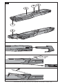
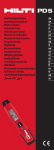
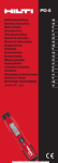
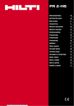
PD 5 Operating instructions Mode d’emploi Manual de instrucciones Manual de instruções Printed: 07.07.2013 | Doc-Nr: PUB / 5145343 / 000 / 00 en fr es pt 1 &/,&. Printed: 07.07.2013 | Doc-Nr: PUB / 5145343 / 000 / 00 ORIGINAL OPERATING INSTRUCTIONS PD 5 laser range meter It is essential that the operating instructions en are read before the laser range meter is used the first time. Ensure that the operating instructions are with the laser range meter when it is given to other persons. Contents 1. General information 2. Description 3. Accessories 4. Technical data 5. Safety instructions 6. Before use 7. Operation 8. Care and maintenance 9. Troubleshooting 10. Disposal 11. Manufacturer’s warranty - tools 12. FCC statement / IC statement Page 1 2 3 3 4 6 7 8 10 11 11 12 These numbers refer to the corresponding illustrations. The illustrations can be found on the fold-out cover pages. Keep these pages open while studying the operating instructions. In these operating instructions, the designation “the tool” always refers to the PD 5 laser range meter. Parts, operating controls and indicators 햲 Laser emitting and receiving lens 햳 On/off button 햴 Measure button 햵 Battery compartment cover 햶 Graphic display 1. General information 1.1 Safety Notices and their meaning -CAUTIONThis word indicates a possibly hazardous situation which could result in slight bodily injuries or damage to property. -NOTEThis word indicates information to help the user employ the product efficiently and other useful notes. 1 Printed: 07.07.2013 | Doc-Nr: PUB / 5145343 / 000 / 00 1.2 Explanation of the pictograms and other information Warning signs Symbols LASER RADIATION - DO NOT STARE INTO BEAM en 620-690nm/0.95mW max. CLASS II LASER PRODUCT General warning Laser class II according to CFR 21, § 1040 (FDA) Symbols >1/4s 2 Read the operating instructions before use. Temperature indicator Do not look into the beam. Laser class 2 Battery status indicator Hardware errors Unfavorable operating conditions KCC-REMHLT-PD5 Return waste material for recycling. 1.3 Location of identification data on the range meter The type designation and serial number can be found on the rating plate on the back side of the range meter. Make a note of this data in your operating instructions and always refer to it when making an enquiry to your Hilti representative or service department. Type: Serial no.: 2. Description 2.1 Intended use The range meter is designed for the: • Measurement of distances 2.2 Display The measurements, settings and tool status are shown in the display. When the tool is in measuring mode, the measurements taken are shown at the bottom of the display area (the result line). 2.3 Display illumination In low light conditions, the display is illuminated automatically as soon as a button is pressed. If no button is pressed over a period of 20 seconds, the display illumination switches off automatically. 2 Printed: 07.07.2013 | Doc-Nr: PUB / 5145343 / 000 / 00 2.4 Basic principle The distance is measured along a laser beam emitted by the tool to the point at which the beam strikes a reflective surface. The target from which the measurement is taken is clearly identified by the red laser measuring spot. The range of the tool depends on the reflectance and structure en of the target surface from which measurements are taken. 2.5 Control panel On/off button When the tool is switched off, press the button briefly to switch it on. When the tool is switched off, press and hold the button to activate the menu. When the tool is switched on, press the button briefly to switch it off. Measure button Quick start (When the tool is switched off: Press the button briefly - the tool switches on and activates the laser). Begins distance measurement. Activates the laser beam. Activates continuous measuring mode (long press, approx. 2 sec.). Stops continuous measuring mode. 2.6 Items supplied 1 PD 5 laser range meter 2 Batteries 1 Soft pouch 1 Operating instructions 1 Manufacturer’s certificate 3. Accessories Not supplied with the tool. Target plate Laser visibility glasses PDA 50 with reflective coating (4.7×5.1 in) PDA 51 (4.7×5.1 in) PDA 52 with reflective coating (8.3×11.7 in) PUA 60 4. Technical data Right of technical changes reserved. Power supply 2×1.5 V, type AAA batteries Battery condition check Battery condition indicator with 4 segments showing 100%, 75%, 50%, 25% charge : No segments shown: The batteries are exhausted 3 Printed: 07.07.2013 | Doc-Nr: PUB / 5145343 / 000 / 00 en Measuring range (with target plate) 10 in … 230 ft Accuracy Typically ±1/16 in for single and continuous measurement ** ** Atmospheric influences interfere with distance measurements. Over long distances, an influence of ±1/16 in + 20 ppm of the measured distance is to be expected. Typical accuracy: 2 Sigma at 77 °F. Basic operating modes Single measurement / Continuous measurement Display Illuminated liquid-crystal display showing distance, operating and battery status Laser class Visible 635 nm, Output power less than 1 mW: Laser class 2 EN 60825-1:2007; IEC 60825-1:2007 CFR 21 § 1040 (FDA) Automatic cut-out Laser: 1 min / Tool: 10 min Battery life Up to 5000 measurements at room temperature Operating temperature range +14 °F … +122 °F Storage temperature -22 °F … +158 °F Protection class IP 55 protection against dust and water jets IEC 60529 Weight with batteries 0.22 lb Dimensions 6.5 × 1.3 × 0.8 in 5. Safety instructions In addition to the information relevant to safety given in each of the sections of these operating instructions, the following points must be strictly observed at all times. 5.1 Basic information concerning safety a) Do not render safety devices ineffective and do not remove information and warning notices. b) Keep laser tools out of reach of children. c) Failure to follow the correct procedures when opening the tool may cause emission of laser radiation in excess of class 2. Have the tool repaired only at a Hilti service center. d) Modification of the tool is not permissible. e) Check that the tool functions correctly each time before use. f) Measurements taken from surfaces with low reflectivity in highly reflective surroundings may be inaccurate. g) Measurements taken through panes of glass or other objects may be inaccurate. 4 Printed: 07.07.2013 | Doc-Nr: PUB / 5145343 / 000 / 00 h) Rapidly changing conditions, e.g. persons walking through the path of the laser beam, falling snow, etc., may lead to incorrect measurements. i) Do not point the tool toward the sun or other powerful light sources. j) Take the influences of the surrounding area into account. Do not use the tool where there is a risk of fire or explo- en sion. 5.2 Proper organization of the workplace a) Avoid unfavorable body positions when working from ladders. Make sure you work from a safe stance and stay in balance at all times. b) When the tool is brought into a warm environment from very cold conditions, or vice-versa, allow it to become acclimatized before use. c) As a precaution, check the previous settings and adjustments you have made. d) Secure the area in which you are working and take care to avoid directing the beam towards other persons or towards yourself when setting up the tool. e) Use the tool only within its specified limits. f) Observe the accident prevention regulations applicable in your country. 5.3 Electromagnetic compatibility Although the tool complies with the strict requirements of the applicable directives, Hilti cannot entirely rule out the possibility of the tool being subject to interference caused by powerful electromagnetic radiation, leading to incorrect operation. Check the accuracy of the tool by taking measurements by other means when working under such conditions or if you are unsure. Likewise, Hilti cannot rule out the possibility of interference with other devices (e.g. aircraft navigation equipment). The tool complies with the requirements of class A; The possibility of interference occurring in a domestic environment cannot be excluded. 5.4 General safety rules a) Check the condition of the tool before use. If the tool is found to be damaged, have it repaired at a Hilti service center. b) The user must check the accuracy of the tool after it has been dropped or subjected to other mechanical stresses. c) Although the tool is designed for the tough conditions of jobsite use, as with other measuring instruments it should be treated with care. d) Although the tool is protected to prevent entry of dampness, it should be wiped dry each time before being put away in its transport container. 5.5 Electrical a) Keep the batteries out of reach of children. b) Do not allow the batteries to overheat and do not expose them to fire. The batteries may explode or release toxic substances. c) Do not charge the batteries. 5 Printed: 07.07.2013 | Doc-Nr: PUB / 5145343 / 000 / 00 d) Do not solder the batteries into the tool. e) Do not discharge the batteries by shortcircuiting. This may cause them to overheat and present a risk of personal injury (burns). f) Do not attempt to open the batteries and do not subject them to excessive mechanical stress. en g) Do not use carbon-zinc batteries in the tool. 5.6 Laser classification Depending on the version purchased, the tool complies with Laser Class 2 in accordance with IEC825-1:2007 / EN60825-1:2007 and Class II in accordance with CFR 21 § 1040 (FDA). This tool may be used without need for further protective measures. The eyelid closure reflex protects the eyes when a person looks into the beam unintentionally for a brief moment. This eyelid closure reflex, however, may be negatively affected by medicines, alcohol or drugs. Nevertheless, as with the sun, one should not look directly into sources of bright light. Do not direct the laser beam toward persons. 5.7 Transport Always remove the batteries before shipping the tool. 6. Before use 6.1 Inserting the batteries CAUTION Do not use damaged batteries. CAUTION Always replace the complete set of batteries. DANGER Do not mix old and new batteries. Do not mix batteries of different makes or types. 1. Open the battery compartment. 2. Remove the batteries from the packaging and insert them in the tool. NOTE Check to ensure correct battery polarity (refer to the markings on the underside of the tool). 3. Close the battery compartment cover. 4. Check to ensure that the battery compartment cover is closed securely. 6.2 Switching the tool on / off 1. The tool can be switched on by pressing either the “On / off” button or the “Measure” button. 2. When the tool is switched off, press the “On / off” button: The tool switches on. The laser beam is switched off. 6 Printed: 07.07.2013 | Doc-Nr: PUB / 5145343 / 000 / 00 3. When the tool is switched on, press the “On / off” button: The tool switches off. 4. When the tool is switched off, press the “Measure” button: The tool and the laser beam switch on. 6.3 First distance measurements en 1. Press the “Measure” button once. If switched off, the tool will be switched on and the laser beam activated. If the tool is already switched on, the laser beam will be activated. 2. Aim the tool by positioning the visible laser spot on a white surface at a distance of approx. 10-30 ft. 3. Press the “Measure” button again. The distance will be displayed in less than a second, e.g. 17.99 ft. You have just taken your first measurement with the tool. 6.4 Settings menu 1. With the tool switched off, press the “On / off” button for approx. 2 seconds to enter menu mode. 2. Press the "Measure" button to switch the beep signal on or off. 3. Press the "On / off" button to access the measuring units settings. 4. Press the "Measure" button repeatedly to scroll through the choice of units. 5. To close the menu, press and hold the "On / off" button for approx. 2 seconds. The tool is switched off and all the settings shown will be saved. 6.5 Measuring references All measurements taken with the PD 5 have the bottom end of the tool as the default reference setting. 6.6 Measuring distances Distances can be measured from all stationary targets without a highly reflective surface, i.e. concrete, stone, wood, plastic, paper, etc. The use of prisms or other highly reflective targets is not permissible and, if attempted, may falsify the results. 7. Operation 7.1 Distance measurements NOTE With all functions of the tool, each step in the operation is always indicated in the display. 7 Printed: 07.07.2013 | Doc-Nr: PUB / 5145343 / 000 / 00 NOTE If measuring errors occur during continuous measuring, and continuous measuring mode is canceled by pressing the “Measure” button again, the last valid measurement will be displayed. en 7.2 Single distance measurement 1. Switch on the laser beam by pressing the “Measure” key. 2. Press the “Measure” key once again. Generally, the measured distance will be completed in less than a second and shown in the result line on the display. 7.3 Continuous measurement Press the “Measure” key for 2 seconds to activate this measuring mode. When doing so, it does not matter whether or not the range meter is off or the laser beam is switched on or off. The range meter will always switch to continuous measurement. During continuous measurement, the distances are updated in the result line by about 8 to 15 measurements every second. This depends on the reflectivity of the target surface. Continuous measurement is indicated by a beep. The measuring process is stopped by pressing the "Measure" key once again. On doing so, the last valid distance measurement shows in the result line on the display. 8. Care and maintenance 8.1 Cleaning and drying 1. Blow dust off the lens. 2. Do not touch the lens with the fingers. 3. Use only a clean, soft cloth for cleaning. If necessary, moisten the cloth slightly with pure alcohol or a little water. NOTE Do not use any other liquids as these may damage the plastic components. 4. The temperature limits for storage of your equipment must be observed, especially in winter / summer. 8.2 Storage Remove the tool from its case if it has become wet. The tool, its carrying case and accessories should be cleaned and dried (at maximum 104 °F). Repack the equipment only once it is completely dry. Check the accuracy of the equipment before it is used after a long period of storage or transportation. Remove the batteries from the tool before storing it for a long period. Leaking batteries may damage the tool. 8.3 Transport Use the original packaging or packaging of equivalent quality for transporting or shipping your equipment. CAUTION Always remove the batteries before shipping the tool. 8 Printed: 07.07.2013 | Doc-Nr: PUB / 5145343 / 000 / 00 8.4 Calibration and adjustment 8.4.1 Calibration Monitoring of measuring equipment for users certified in accordance with ISO 900X: As specified in ISO 900X, you may carry out the inspection and testing of the PD 5 laser range meter yourself (see ISO 17123-4: Field procedures en for testing geodetic and surveying instruments: Part 4, Electro-optical distance meters). 1. Select a readily accessible measuring distance of a known length (approx. 3 ft … 15 ft) which does not change over time and measure the same distance 10 times. 2. Determine the mean deviation from the known distance. This value should be within the specified accuracy tolerance for the tool. 3. Keep a record of this value and note the date when the next test is due. Repeat this test at regular intervals as well as before and after important measuring tasks. Apply a test and inspection confirmation sticker to the PD 5 and keep a record of the entire monitoring, test and inspection procedure and the results. Please refer to the technical data contained in the operating instructions and the information concerning measuring accuracy. 8.4.2 Adjustment To ensure that the laser range meter is adjusted correctly, we recommend that it is returned to a Hilti Service Center for calibration. Accurate adjustment of the tool will be confirmed by a calibration certificate. 8.4.3 Hilti calibration service We recommend that the tool is checked by the Hilti calibration service at regular intervals in order to verify its reliability in accordance with standards and legal requirements. Use can be made of the Hilti calibration service at any time, but checking at least once a year is recommended. The calibration service provides confirmation that the tool is in conformance, on the day it is tested, with the specifications given in the operating instructions. The tool will be readjusted if deviations from the manufacturer’s specification are found. After checking and adjustment, a calibration sticker applied to the tool and a calibration certificate provide written verification that the tool operates in accordance with the manufacturer’s specification. Calibration certificates are always required by companies certified according to ISO 900x. Your local Hilti Center or representative will be pleased to provide further information. 9 Printed: 07.07.2013 | Doc-Nr: PUB / 5145343 / 000 / 00 9. Troubleshooting en Fault 1. The tool can’t be switched on. 2. No distances displayed by the tool. 3. Frequent error messages or the tool doesn’t measure. 4. Temperature indicator - symbol in the display 5. Unfavorable signal conditions - symbol in the display 6. General hardware fault - symbol in the display Possible cause 1.1 The batteries are exhausted. 1.2 Incorrect battery polarity. 1.3 The button is faulty. 2.1 “Measure” button was not pressed. 2.2 Faulty display. 3.1 The target surface is too brightly lit by the sun. 3.2 The target surface is too shiny. 3.3 The target surface is too dark. 3.4 Bright sunlight towards the tool. 4.1 Temperature too high (>+122 °F) 4.2 Temperature too low (<+ 14 °F) 5.1 Insufficient reflected laser light. 6.1 Hardware fault Remedy 1.1 Replace the batteries. 1.2 Insert the batteries correctly and close the battery compartment cover. 1.3 Return the tool to Hilti for repair. 2.1 Press the “Measure” button. 2.2 Return the tool to Hilti for repair. 3.1 Measure from the other direction – sun from behind. 3.2 Take measurements from less shiny surfaces. 3.3 Use the PDA 50 / PDA 51 / PDA 52 target plate. 3.4 Use the PDA 50 / PDA 51 / PDA 52 target plate. 4.1 Allow the tool to cool down. 4.2 Allow the tool to warm up. 5.1 Observe the minimum measuring distance (>9.84 inches from the front edge of the tool); clean the lenses; take the measurement from a different surface or use a target plate. 6.1 Switch the tool off and on again. If the fault persists, contact Hilti Service. 10 Printed: 07.07.2013 | Doc-Nr: PUB / 5145343 / 000 / 00 10. Disposal WARNING Improper disposal of the equipment may have serious consequences: The burning of plastic components generates toxic fumes which may present a health hazard. Batteries may explode if damaged or exposed to very high temperatures, causing poisoning, burns, acid burns or environmental pollution. Careless disposal may permit unauthorized and improper use of the equipment. This may result in seriou personal injury, injury to third parties and pollution of the environment. Most of the materials from which Hilti tools or appliances are manufactured can be recycled. The materials must be correctly separated before they can be recycled. In many countries, Hilti has already made arrangements for taking back old tools and appliances for recycling. Ask Hilti customer service or your Hilti representative for further information. Dispose of the batteries in accordance with national regulations. 11. Manufacturer’s warranty – tools Hilti warrants that the tool supplied is free of defects in material and workmanship. This warranty is valid so long as the tool is operated and handled correctly, cleaned and serviced properly and in accordance with the Hilti Operating Instructions, and the technical system is maintained. This means that only original Hilti consumables, components and spare parts may be used in the tool. This warranty provides the free-of-charge repair or replacement of defective parts only over the entire lifespan of the tool. Parts requiring repair or replacement as a result of normal wear and tear are not covered by this warranty. Additional claims are excluded, unless stringent national rules prohibit such exclusion. In particular, Hilti is not obligated for direct, indirect, incidental or consequential damages, losses or expenses in connection with, or by reason of, the use of, or inability to use the tool for any purpose. Implied warranties of merchantability or fitness for a particular purpose are specifically excluded. 11 Printed: 07.07.2013 | Doc-Nr: PUB / 5145343 / 000 / 00 en For repair or replacement, send tool or related parts immediately upon discovery of the defect to the address of the local Hilti marketing organization provided. This constitutes Hilti's entire obligation with regard to warranty and supersedes all prior or contemporaneous comen ments and oral or written agreements concerning warranties. 12. FCC statement / IC statement -CAUTIONThis equipment has been tested and found to comply with the limits for a class B digital device, pursuant to part 15 of the FCC rules. These limits are designed to provide reasonable protection against harmful interference in a residential installation. This equipment generates, uses, and can radiate radiofrequency energy and, if not installed and used in accordance with the instructions, may cause harmful interference to radio communications. However, there is no guarantee that interference will not occur in a particular installation. If this equipment does cause harmful interference to radio or television reception, which can be determined by turning the equipment on and off, the user is encouraged to try to correct the interference by one or more of the following measures: • Re-orient or re-locate the receiving antenna. • Increase the distance between the equipment and receiver. • Connect the equipment to an outlet on a circuit different from that to which the receiver is connected. • Consult the dealer or an experienced TV/radio technician for assistance. -NOTEChanges or modifications not expressly approved by the party responsible for compliance could void the user’s authority to operate the equipment. This device complies with part 15 of the FCC Rules. Operation is subject to the following two conditions: 1) this device may not cause harmful interference, and 2) this device must accept any interference received, including interference that may cause undesired operation. This device complies with the requirements defined in RSS210 of IC. Operation is subject to the following two conditions: 1) this device may not cause harmful interference, and 2) this device must accept any interference received, including interference that may cause undesired operation. 12 Printed: 07.07.2013 | Doc-Nr: PUB / 5145343 / 000 / 00 Hilti Corporation 2008240 / A2 Printed: 07.07.2013 | Doc-Nr: PUB / 5145343 / 000 / 00 2008240 Hilti = registered trademark of Hilti Corp., Schaan W 3917 0613 00-Pos. 3 1 Printed in Germany © 2013 Right of technical and programme changes reserved S. E. & O. *2008240* LI-9494 Schaan Tel.: +423 / 234 21 11 Fax: +423 / 234 29 65 www.hilti.com Printed: 07.07.2013 | Doc-Nr: PUB / 5145343 / 000 / 00