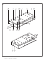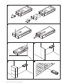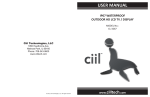
1
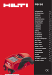
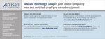
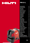
PD 40
Bedienungsanleitung
de
Operating instructions
en
Mode d’emploi
fr
Istruzioni d’uso
it
Manual de instrucciones
es
Manual de instruções
pt
Gebruiksaanwijzing
nl
Οδηγιες χρησεως
el
Kulllanma Talimatı
tr
ar
Printed: 20.12.2013 | Doc-Nr: PUB / 5137540 / 000 / 01
1
+≠
+± +“
4
3
+#
1
6
8
9
7 5
+[ +Ç
Printed: 20.12.2013 | Doc-Nr: PUB / 5137540 / 000 / 01
2
2
2
1
4
3
6
5
3
1
2
4
5
1
6
Printed: 20.12.2013 | Doc-Nr: PUB / 5137540 / 000 / 01
7
ORIGINAL OPERATING INSTRUCTIONS
PD 40 laser range meter
It is essential that the operating instructions
are read before the tool is operated for the
first time.
Always keep these operating instructions together with the tool.
Ensure that the operating instructions are
with the tool when it is given to other persons.
Contents
1 General information
2 Description
3 Insert tools, accessories
4 Technical data
5 Safety instructions
6 Before use
7 Operation
8 Care and maintenance
9 Troubleshooting
10 Disposal
11 Manufacturer’s warranty - tools
12 EC declaration of conformity (original)
Page
15
16
19
19
20
21
24
26
27
27
28
28
1 These numbers refer to the corresponding illustrations. The illustrations can be found on the fold-out cover
pages. Keep these pages open while studying the operating instructions.
In these operating instructions, the designation “the tool”
always refers to the PD 40 laser range meter.
Parts, operating controls and indicators 1
@ On/off button
; Side measure button
= Graphic display
% Measure button
& Delete (clear) button
( Horizontal bubble
) Area button
+ Folding spike
§ ¹/₄" thread for PDA 71 measuring extension
/ Rear contact points
: Minus button
· Plus button
$ Reference button
£ Laser exit lens
| Receiving lens
1 General information
1.1 Safety notices and their meaning
DANGER
Draws attention to imminent danger that will lead to
serious bodily injury or fatality.
WARNING
Draws attention to a potentially dangerous situation that
could lead to serious personal injury or fatality.
CAUTION
Draws attention to a potentially dangerous situation that
could lead to slight personal injury or damage to the
equipment or other property.
1.2 Explanation of the pictograms and other
information
Warning signs
General
warning
NOTE
Draws attention to an instruction or other useful information.
15
Printed: 20.12.2013 | Doc-Nr: PUB / 5137540 / 000 / 01
en
Symbols
Type identification plate
PD 40 01
Hilti = trademark of Hilti Corp., Schaan, LI
Made in Germany
Serial number
Return waste
material for
recycling.
AVOID EXPOSURE
Laser radiation is emitted from this aperture
Laser class II
according to
CFR 21, § 1040
(FDA)
LASER RADIATION - DO NOT
STARE INTO BEAM
620-690nm/0.95mW max.
CLASS II LASER PRODUCT
30392 / 11.2008
en
Read the
operating
instructions
before use.
DIN EN 60825-1:2007
>1/4s
Laser class 2
according to
EN 608253:2007
Do not look
into the
beam.
This device complies with part 15 of
the FCC Rules. (1) This device may not
cause harmful interference, and (2) this
device must accept any interference received, including interference that may cause undesired operation.
Temperature
indicator
Item No.: 30399
Power: 3V nom/400 mA
Manufactured:
PD 40
Battery status
indicator
Hardware
errors
Unfavorable
operating
conditions
Location of identification data on the tool
The type designation and serial number can be found on
the type identification plate on the tool. Make a note of
this data in your operating instructions and always refer
to it when making an enquiry to your Hilti representative
or service department.
Type:
Serial no.:
2 Description
2.1 Use of the product as directed
The tool is designed for measuring distances, calculating areas and adding or subtracting distances.
Do not use the tool as a leveling tool.
Measurements taken from plastic foam materials such as polystyrene foam, from snow or from highly reflective
surfaces (mirrors, glass, etc.) may produce inaccurate results.
The tool and its ancillary equipment may present hazards when used incorrectly by untrained personnel or when used
not as directed.
Take the influences of the surrounding area into account. Do not use the appliance where there is a risk of fire or
explosion.
Observe the information printed in the operating instructions concerning operation, care and maintenance.
To avoid the risk of injury, use only genuine Hilti accessories and additional equipment.
Modification of the tool is not permissible.
NOTE
Observe the permissible operating and storage temperatures.
2.2 Display
The measurements, settings and tool status are shown in the display. When the tool is in measuring mode, the
measurements taken are shown at the bottom of the display area (the result line). When using a function, e.g. area
measurement, the distances measured are shown in the intermediate result line and the calculated result is shown at
the bottom of the display (the result line).
16
Printed: 20.12.2013 | Doc-Nr: PUB / 5137540 / 000 / 01
2.3 Display illumination
In low light conditions, the display is illuminated automatically as soon as a button is pressed. The display illumination
intensity is reduced to 50% after 10 seconds. If no button is pressed over a period of 20 seconds, the display
illumination switches off automatically.
NOTE
Illumination of the display consumes battery power. Shorter battery life is therefore to be expected when this feature
is used frequently.
2.4 Basic principle
The distance is measured along a laser beam emitted by the tool to the point at which the beam strikes a reflective
surface. The target from which the measurement is taken is clearly identified by the red laser measuring spot. The
range of the tool depends on the reflectance and structure of the target surface from which measurements are taken.
2.5 Measuring principle
The tool emits a visible laser beam carrying signal pulses which are reflected by the target. The time between reflected
pulses is used as a basis for determining the distance.
This measuring principle permits highly accurate and reliable measurement of distances to objects without need for
special reflectors.
2.6 Standard measuring display mode
Standard measuring display mode is always activated when the “On/off” or “Measure” button is pressed to switch the
tool on.
2.7 Symbols in the display
Temperature
Temperature too high
(>+50°C) / too low (<-10°C).
Unfavorable conditions, poor signal
Insufficient reflected laser
light.
General hardware error
Allow the tool to cool down or warm up.
Observe the minimum measuring distance (50 mm from the front edge of the
tool); clean the lenses; take measurements from a different surface or use a
target plate.
Switch the tool off and on again. If the fault persists, please contact Hilti
Service.
2.8 Control panel
On/off button
When the tool is switched off, press the button briefly to switch it on.
When the tool is switched off, press and hold the button to activate the
menu.
When the tool is switched on, press the button briefly to switch it off.
Measure button
Activates the laser beam.
Begins distance measurement.
Activates continuous measuring mode (long press, approx. 2 sec.).
Stops continuous measuring mode.
Plus button
Activates distance and area addition.
Adds distances shown in the standard measuring display.
Adds areas when in area measuring mode.
Minus button
Activates distance and area subtraction.
Subtracts distances shown in the standard measuring display.
Subtracts areas when in area measuring mode.
Area button
Activates area measuring mode.
17
Printed: 20.12.2013 | Doc-Nr: PUB / 5137540 / 000 / 01
en
Area button
When measurements have already been taken: Deletes all measurements
and restarts the function.
When no measurements have been taken: Ends area measuring mode.
Stops continuous measuring (tracking).
Delete (clear) button
en
Stops continuous measuring (tracking).
The C‑button has various
functions depending on operating mode.
Clears the standard measurement display.
Clears the last measurement and returns to “Functions”.
Ends area measuring mode if no measurements have been taken.
Reference button
Switches the various measuring references between front and rear.
2.9 Battery condition indicator
Number of segments shown
Charge status in %
4
= 100 % capacity
3
= 75 % capacity
2
= 50 % capacity
1
= 25 % capacity
0
Fully discharged
2.10 Items supplied as standard
1
PD 40 laser range meter
2
Batteries
1
1
1
1
Hand strap
Battery compartment key
Operating instructions
Manufacturer’s certificate
2.11 PUA 60 laser visibility glasses
The laser visibility glasses have no protective function and thus do not protect the eyes from laser beams. As these
glasses limit color vision they must not be worn by persons driving on a public road and must not be used to look
directly into the sun.
The PUA 60 laser visibility glasses improve laser beam visibility considerably.
2.12 PDA 50 / 51 / 52 target plate
The PDA 50 target plate is made of durable plastic with a special reflective coating. Use of the target plate is
recommended at distances greater than 10 m in poor light conditions.
The PDA 51 target plate has no reflective coating and its use is recommended in poor light conditions and at short
distances. The PDA 52 target plate is equipped with the same reflective coating as the PDA 50 but is considerably
larger in size (A4 format, 210 x 297 mm). This makes it much easier to aim the tool at the target plate over long
distances.
NOTE
For reliable distance measurements, care should be taken to ensure that the laser beam strikes the target plate at
right angles as far as possible. The laser spot on the target plate and the measuring reference point (starting point)
may otherwise be in different planes (parallax error).
NOTE
When the target plate is used and very high accuracy is required, 1.2 mm should be added to the measurement
obtained.
18
Printed: 20.12.2013 | Doc-Nr: PUB / 5137540 / 000 / 01
2.13 PDA 71 measuring extension
The measuring extension is made from aluminium and is equipped with a non-conductive synthetic rubber grip. The
screw on the measuring extension should be screwed into the threaded bush on the rear contact surface of the PD
40. When the measuring extension is screwed onto the tool, the rear reference is then relocated to the tip of the
measuring extension, i.e. the rear reference is extended by 1270 mm (50 inches).
en
3 Insert tools, accessories
Designation
Description
Target plate
PDA 50
Target plate
PDA 51
Target plate
PDA 52
Measuring extension
PDA 71
Designation
Description
Hand strap
PDA 60
Soft pouch
PDA 65
Laser visibility glasses
PUA 60
4 Technical data
Right of technical changes reserved.
Technical data
Values
Power supply
3V DC AA-size batteries
Battery condition check
Battery condition indicator with 4 segments showing 100%, 75%, 50%, 25% charge : No segments
shown: The batteries are exhausted
0.05…200 m
Measuring range
Typical measuring range without target plate
Accuracy
Smallest unit displayed
Beam diameter
Basic operating modes
Display
Laser
Automatic cut-out
Battery life
Operating temperature range
Drywall panel, white: 100 m
Concrete, dry: 70 m
Brick, dry: 50 m
Typically ±1.0 mm for single and continuous measurement
1 mm
Beam length 10 m: Max. 6 mm
Beam length 50 m: Max. 30 mm
Beam length 100 m: Max. 60 mm
Single measuring, continuous measuring,
calculation/functions
Illuminated dot-matrix display with permanent indication of operating mode and battery condition
Visible 635 nm, Output power less than 1 mW: Laser
class 2
IEC 825‑ 1:2007; CFR 21 § 1040 (FDA)
Laser: 1 min
Tool: 10 min
Max. number of measurements with laser beam
switched on for a time of 10 s Alkaline 8,000…
10,000 NiMH 6,000…8,000
-10…+50°C
19
Printed: 20.12.2013 | Doc-Nr: PUB / 5137540 / 000 / 01
en
Technical data
Values
Storage temperature
-30…+70°C
Protection class (except battery compartment)
Weight without batteries
IP 54 protection against dust and water jets
IEC 529
170 g
Dimensions
120 mm x 55 mm x 28 mm
Menu / units
m
cm
mm
Distance
Area
Meters
m²
Volume
m³
Centimeters
m²
m³
m³
Millimeters
m²
In
Inches, decimal
Inches²
Inches³
In ¹/₈
¹/₈ inch
Inches²
Inches³
In ¹/₁₆
¹/₁₆ inch
Inches²
Inches³
In ¹/₃₂
¹/₃₂ inch
Inches²
Inches³
Ft
Feet, decimal
Feet²
Feet³
Ft ¹/₈
Feet-inches-¹/₈
Feet²
Feet³
Ft ¹/₁₆
Feet-inches-¹/₁₆
Feet²
Feet³
Ft ¹/₃₂
Feet-inches-¹/₃₂
Feet²
Feet³
Yd
Yards, decimal
Yards²
Yards³
5 Safety instructions
In addition to the information relevant to safety given
in each of the sections of these operating instructions,
the following points must be strictly observed at all
times.
5.1 Basic information concerning safety
Do not render safety devices ineffective and do
not remove information and warning notices.
b) Keep laser tools out of reach of children.
c) Failure to follow the correct procedures when opening the tool may cause emission of laser radiation in
excess of class 2. Have the tool repaired only at a
Hilti service center.
d) Check that the tool functions correctly each time
before use.
e) Operation of the tool in the proximity of pregnant
women is not permissible.
f) Measurements taken from surfaces with low reflectivity in highly reflective surroundings may be inaccurate.
g) Measurements taken through panes of glass or other
objects may be inaccurate.
h) Rapid changes in the conditions under which the
measurement is taken, e.g. persons walking through
the laser beam, may lead to inaccurate results.
i) Do not point the tool toward the sun or other
powerful light sources.
a)
20
Printed: 20.12.2013 | Doc-Nr: PUB / 5137540 / 000 / 01
5.2 Proper organization of the workplace
Avoid unfavorable body positions when working
from ladders. Make sure you work from a safe
stance and stay in balance at all times.
b) Check the measuring reference setting before
taking the measurement.
c) When the tool is brought into a warm environment
from very cold conditions, or vice-versa, allow it
to become acclimatized before use.
d) As a precaution, check the previous settings and
adjustments you have made.
e) When setting up the tool with the aid of the bubble
level, view the bubble level at a slight angle.
f) Secure the area in which you are working and
take care to avoid directing the beam towards
other persons or towards yourself when setting
up the tool.
g) Use the tool only within its specified limits.
h) Observe the accident prevention regulations applicable in your country.
a)
5.3 Electromagnetic compatibility
Although the tool complies with the strict requirements of
the applicable directives, Hilti cannot entirely rule out the
possibility of the tool being subject to interference caused
by powerful electromagnetic radiation, leading to incorrect operation. Check the accuracy of the tool by taking
measurements by other means when working under such
conditions or if you are unsure. Likewise, Hilti cannot rule
out the possibility of interference with other devices (e.g.
aircraft navigation equipment). The tool complies with the
requirements of class A; The possibility of interference
occurring in a domestic environment cannot be excluded.
5.4 General safety rules
Check the condition of the tool before use. If the
tool is found to be damaged, have it repaired at a
Hilti service center.
b) The user must check the accuracy of the tool
after it has been dropped or subjected to other
mechanical stresses.
c) Although the tool is designed for the tough conditions of jobsite use, as with other measuring
instruments it should be treated with care.
d) Although the tool is protected to prevent entry
of dampness, it should be wiped dry each time
before being put away in its transport container.
a)
5.5 Electrical
a)
Keep the batteries out of reach of children.
b) Do not allow the batteries to overheat and do not
expose them to fire. The batteries may explode or
release toxic substances.
c) Do not charge the batteries.
d) Do not solder the batteries into the tool.
e) Do not discharge the batteries by short-circuiting.
This may cause them to overheat and present a risk
of personal injury (burns).
f) Do not attempt to open the batteries and do not
subject them to excessive mechanical stress.
5.6 Laser classification
Depending on the version purchased, the tool complies
with Laser Class 2 in accordance with IEC825-3:2007 /
EN60825-3:2007 and Class II in accordance with CFR
21 § 1040 (FDA). This tool may be used without need
for further protective measures. The eyelid closure reflex
protects the eyes when a person looks into the beam
unintentionally for a brief moment. This eyelid closure
reflex, however, may be negatively affected by medicines,
alcohol or drugs. Nevertheless, as with the sun, one
should not look directly into sources of bright light. Do
not direct the laser beam toward persons.
5.7 Transport
Always remove the batteries before shipping the tool.
6 Before use
2.
3.
6.1 Inserting the batteries 2
CAUTION
Do not use damaged batteries.
CAUTION
Always replace the complete set of batteries.
4.
6.3 First distance measurements
1.
DANGER
Do not mix old and new batteries. Do not mix batteries
of different makes or types.
2.
1.
3.
2.
3.
Unscrew the battery compartment cover from the
rear of the tool.
Remove the batteries from the packaging and insert
them in the tool.
NOTE Take care to observe correct polarity (see
symbols in battery compartment).
Check to ensure that the battery compartment cover
is closed securely.
When the tool is switched off, press the “On / off”
button: The tool switches on.
The laser beam is switched off.
When the tool is switched on, press the “On / off”
button: The tool switches off.
When the tool is switched off, press the “Measure”
button: The tool and the laser beam switch on.
Press the “Measure” button once.
If switched off, the tool will be switched on and the
laser beam activated.
If the tool is already switched on, the laser beam will
be activated.
Aim the tool by positioning the visible laser spot on
a white surface at a distance of approx. 3 - 10 m.
Press the “Measure” button again.
The distance will be displayed in less than a second,
e.g. 5.489 m.
You have just taken your first measurement with the
tool.
6.2 Switching the tool on / off
1.
The tool can be switched on by pressing either the
“On / off” button or the “Measure” button.
21
Printed: 20.12.2013 | Doc-Nr: PUB / 5137540 / 000 / 01
en
6.4 Settings menu
MENU
PDA 71 measuring extension: is detected automatically
when screwed in.
en
6.6 Measuring distances
m
1.
2.
3.
4.
With the tool switched off, press the “On / off” button
for approx. 2 seconds to enter menu mode.
Press the “Plus” button to switch the beep signal on
or off.
Press the “Minus” button repeatedly to scroll
through the choice of units.
Press the “On / off” button briefly to close the menu.
The tool is switched off and all the settings shown
will be saved.
6.5 Measuring references
NOTE
The tool can take measurements from 4 different reference (contact) points. The “Reference” button on the
left on the front of the tool is used to switch between
the front and rear references (front or rear edge of the
tool). The reference is set automatically to the tip of the
spike when the spike is folded out through 180°. When
the measuring extension is screwed into place, this is
detected automatically by the tool and indicated by the
long extension symbol in the display.
Front edge
Rear edge
Spike
22
Printed: 20.12.2013 | Doc-Nr: PUB / 5137540 / 000 / 01
NOTE
When the spike is folded back in, the measuring reference
is always reset to the rear edge of the tool irrespective of
how far the spike was folded out or to which point on the
tool the measuring reference was previously set.
Distances can be measured from all stationary targets
without a highly reflective surface, i.e. concrete, stone,
wood, plastic, paper, etc. The use of prisms or other
highly reflective targets is not permissible and, if attempted, may falsify the results.
6.6.1 Measuring distances step by step
NOTE
The range meter measures distances in a very short
time and simultaneously shows various information in the
display.
Switch the tool on by pressing the “On / off” button.
----------
m
Press the “Measure” button once. The laser beam is
switched on and is visible in the form of a spot on
the target surface. This aiming mode is indicated in the
display by a blinking laser symbol.
measuring. Continuous measuring mode is used for setting out given distances or lengths and can also be used
where distance measurement is otherwise difficult, e.g.
at corners, edges or in niches, etc.
6.6.2.1 Single distance measuring (“Measure”
button)
1.
2.
----------
m
Switch the laser beam on by pressing the “Measure”
button.
Press the “Measure” button again.
The measured distance will be shown in the result
line at the bottom of the display in less than a
second.
6.6.2.2 Single distance measuring (“On /off” button)
Aim at the target. Press the “Measure” button once again
to measure the distance. The result usually appears in
the result line in less than a second and the laser beam
then switches off.
1.
2.
3.
Switch the laser beam on by pressing the “On / off”
button.
Press the “Measure” button to switch the laser beam
on and then aim the tool at the target.
Press the “Measure” button again.
The measured distance will be shown in the result
line at the bottom of the display in less than a
second.
6.6.2.3 Continuous measuring (tracking)
NOTE
Continuous measuring is possible in all situations where
individual distances can be measured. This applies also
to functions, such as areas.
5.489
m
1.
If further measurements are taken, up to three previously
determined distances are shown in the intermediate result
lines, i.e. a total of the last four measured distances are
shown.
5.489
m
12.349
m
24.634
m
27.317
m
The tool can, of course, be switched on again at any time
by pressing the “Measure” button. Pressing the C-button
clears all currently displayed values.
6.6.2 Measuring modes
Distances can be measured using two different measuring modes, i.e. single distance measuring or continuous
2.
Press the “Measure” button for about 2 seconds to
activate the continuous measuring mode.
NOTE When doing so, it doesn’t matter whether the
tool or the laser beam is switched on or off. The tool
will always switch to continuous measuring mode.
During continuous measuring, distances are updated in the result line at the rate of approx. 6 - 10
measurements every second. The measuring rate
depends on reflectivity of the target surface. If the
beep signal is active, continuous measuring is indicated by a beep signal approx. 2 - 3 times per
second.
Measuring is stopped by pressing the “Measure”
button once again.
The last valid measurement is then shown in the
result line in the display.
6.6.3 Measuring from corners 3 4
The spike is used when measuring diagonally across
rooms or from inaccessible corners.
1. Fold out the spike through 180°.
The measuring reference is then set automatically
to the end of the spike. The range meter takes the
extended reference point into account and corrects
the measured distances accordingly.
2. Position the range meter with the spike at the desired
starting point for the measurement and aim toward
the target.
3. Press the “Measure” button.
The measured distance is shown in the display.
23
Printed: 20.12.2013 | Doc-Nr: PUB / 5137540 / 000 / 01
en
6.6.4 Measuring with the aid of target objects 5 6
When taking measurements to outside corners (e.g. on
outside walls of buildings, perimeter fences, etc.), boards,
bricks or other suitable objects can be held against the
corner and used as the target. Use of the PDA 50, PDA 51
or PDA 52 target plate is recommended for long distances
and in unfavorable light conditions, e.g. in strong sunlight.
en
6.6.5 Measuring in bright conditions
We recommend use of the PDA 50, PDA 51 or PDA 52
target plate for long distances and in very bright light
conditions.
6.6.6 Taking measurements to rough surfaces 7
When measuring to rough surfaces, e.g. rough plaster
etc., an average distance value is measured with the
center of the laser spot weighted higher than the edges
of the laser spot.
6.6.7 Taking measurements to curved or inclined
surfaces
If the laser beam strikes the target surface at a very
narrow angle, the light reflected may be inadequate.
Conversely, too much light may be reflected toward the
tool in situations where the laser beam strikes the target
perpendicularly. We recommend use of the PDA 50, PDA
51 or PDA 52 target plate in both of these situations.
6.6.8 Taking measurements to wet or shiny
surfaces
As long as the range meter can be aimed directly at
the surface, the distance to the target will be reliably
measured. With highly reflective surfaces, a reduction in
range must be expected and the distance to the actual
point of reflection may be measured.
6.6.9 Taking measurements to transparent surfaces
It is generally possible to measure distances to transparent or semi-transparent materials, e.g. liquids, polystyrene foam, etc. Light penetrates these materials, however, and measuring errors may therefore occur. Measuring errors may also occur when measurements are taken
through glass or if objects are present within the line of
the laser beam.
6.6.10 Measuring range
6.6.10.1 Increased range
The range of the tool is generally increased when measurements are taken in the dark, at dawn or dusk and
when the target and/or the tool is shaded from bright
light.
Use of the PDA 50, PDA 51 or PDA 52 target plate also
increases the range of the tool.
6.6.10.2 Reduced measuring range
Measuring range may be reduced in bright conditions,
e.g. in bright sunlight or when working under very powerful floodlights.
The range of the tool may be reduced when measurements are taken through glass or when objects lie within
the path of the laser beam.
The range of the tool may be reduced when measurements are taken to mat green, blue or black surfaces or
to wet or shiny surfaces.
7 Operation
7.2 Adding distances
7.1 Distance measurements
NOTE
With all functions of the tool, each step in the operation
is always indicated in the display.
NOTE
Continuous measuring mode can be used with all functions in which individual distance measurement is possible.
NOTE
If measuring errors occur during continuous measuring,
and continuous measuring mode is canceled by pressing
the “Measure” button again, the last valid measurement
will be displayed.
24
Printed: 20.12.2013 | Doc-Nr: PUB / 5137540 / 000 / 01
12.349 m
+
5.489 m
17.838
m
Individual distances can be conveniently added. This is
useful, for example, for determining the total length of
the inner face of door or window openings or for adding
several individual distances that form a perimeter.
1. Press the “Measure” button (the laser beam will
switch on).
2. Aim the range meter at the target.
3. Press the “Measure” button.
The first distance will be measured and displayed
(the laser then switches off).
4. Press the “Plus” button. The first distance is then
displayed in the middle result line and a plus sign
appears in the lower (intermediate) result line (the
laser beam switches on).
5. Aim the range meter at the target.
6. Press the “Measure” button.
The second distance is then measured and displayed in the lower (intermediate) result line. The
result of the addition is shown in the result line.
The current total of the distances is always shown
in the result line.
The procedure can be repeated until all distances
have been added.
7. To terminate the addition of distances, simply measure a distance without first pressing the “Plus” button.
All previous measuring and calculation results are
shown in the intermediate results lines.
8. Press the C-button to clear the display.
7.3 Subtracting distances
3.947 m
-
3.322 m
0.625
m
Individual distances can be conveniently subtracted from
each other, e.g. in order to determine the distance
between the underside of a pipe and the ceiling. This
can be done by subtracting the distance between the
floor and the underside of the pipe from the distance
between the floor and the ceiling. If the pipe diameter is
subtracted, the result is the distance between the top of
the pipe and the ceiling.
1. Press the “Measure” button (the laser beam
switches on).
2. Aim the range meter at the target.
3. Press the “Measure” button. The first distance will
be measured and displayed (the laser then switches
off).
4.
5.
6.
7.
8.
Press the “Minus” button. The first distance is then
displayed in the middle result line and a minus sign
appears in the lower (intermediate) result line (the
laser beam switches on).
Aim the range meter at the target.
Press the “Measure” button.
The second distance is then measured and displayed in the lower (intermediate) result line.
The result of the subtraction is shown in the result
line.
The current difference in distance is always shown
in the result line.
The procedure can be repeated until all distances
have been subtracted.
To terminate the subtraction of distances, simply
measure a distance without first pressing the
“Minus” button.
All previous measuring and calculation results are
shown in the intermediate results lines.
Press the C-button to clear the display.
7.4 Measuring areas
5.489
m
12.349
m
67.784
3
2
m
Each step of the area measurement operation is indicated
graphically in the display. For example, to determine the
floor area of a room, proceed as follows:
1. Press the “Area” button to activate area measuring
mode.
NOTE When the area function is activated, the laser
beam is already switched on.
2. Aim the range meter at the target.
3. Press the “Measure” button.
For example, to determine the floor area of a room,
proceed as follows:.
The graphic display automatically prompts you to
measure the length of the room.
4. Aim the tool at the next target to obtain the length
of the room.
25
Printed: 20.12.2013 | Doc-Nr: PUB / 5137540 / 000 / 01
en
5.
Press the “Measure” button.
The second distance is then measured, the area
calculated immediately and the result is displayed
in the result line.
Both distances used for the area calculation are
shown in the intermediate result lines and can be
noted down conveniently at the end of the operation.
6.
The C-button can be pressed at any time to stop
the measuring operation. Each measurement can
then be cleared, one after the other, and measuring
restarted.
NOTE If the C-button is pressed several times or the
FNC-button is pressed, the function will be canceled
or, respectively, restarted.
NOTE If the second distance is measured using
continuous measuring mode (tracking), the result of
the area calculation is updated continuously. This
allows parts of the area to be included/excluded.
NOTE After calculation of an area, the “Plus” button
can be pressed to add another area or, respectively,
the “Minus” button used to subtract an area.
2.
Determine the mean deviation from the known distance. This value should be within the specified
accuracy tolerance for the tool.
Keep a record of this value and note the date when
the next test is due.
Repeat this test at regular intervals as well as before
and after important measuring tasks.
Apply a test and inspection confirmation sticker to
the PD 40 and keep a record of the entire monitoring,
test and inspection procedure and the results.
Please refer to the technical data contained in the
operating instructions and the information concerning measuring accuracy.
en
8 Care and maintenance
8.1 Cleaning and drying
1.
2.
3.
4.
Blow dust off the lenses.
Do not touch the glass or the filter with the fingers.
Use only a clean, soft cloth for cleaning. If necessary,
moisten the cloth slightly with pure alcohol or a little
water.
NOTE Do not use any other liquids as these may
damage the plastic components.
The temperature limits for storage of your equipment
must be observed, especially in winter / summer.
8.2 Storage
Remove the tool from its case if it has become wet.
The tool, its carrying case and accessories should be
cleaned and dried (at maximum 40°C / 104°F). Repack
the equipment only once it is completely dry.
Check the accuracy of the equipment before it is used
after a long period of storage or transportation.
Remove the batteries from the tool before storing it for a
long period. Leaking batteries may damage the tool.
8.3 Transport
Use the Hilti toolbox or packaging of equivalent quality
for transporting or shipping your equipment.
CAUTION
Always remove the batteries before shipping the tool.
8.4 Calibration and adjustment
8.4.1 Calibration
Monitoring of measuring equipment for users certified in
accordance with ISO 900X: As specified in ISO 900X, you
may carry out the inspection and testing of the PD 40 laser
range meter yourself (see ISO 17123-4: Field Process for
Accuracy Examination of Geodetic Instruments: Part 6,
Close-range Opto-electrical Range Meters).
1. Select a readily accessible measuring distance of a
known length (approx. 1 to 5 meters / 3 to 15 feet)
which does not change over time and measure the
same distance 10 times.
26
Printed: 20.12.2013 | Doc-Nr: PUB / 5137540 / 000 / 01
3.
8.4.2 Adjustment
To ensure that the laser range meter is adjusted correctly,
we recommend that it is returned to a Hilti Service Center
for calibration. Accurate adjustment of the tool will be
confirmed by a calibration certificate.
8.4.3 Hilti calibration service
We recommend that the tool is checked by the Hilti calibration service at regular intervals in order to verify its
reliability in accordance with standards and legal requirements.
Use can be made of the Hilti calibration service at any
time, but checking at least once a year is recommended.
The calibration service provides confirmation that the
tool is in conformance, on the day it is tested, with the
specifications given in the operating instructions.
The tool will be readjusted if deviations from the manufacturer’s specification are found. After checking and
adjustment, a calibration sticker applied to the tool and
a calibration certificate provide written verification that
the tool operates in accordance with the manufacturer’s
specification.
Calibration certificates are always required by companies
certified according to ISO 900x.
Your local Hilti Center or representative will be pleased
to provide further information.
9 Troubleshooting
Fault
Possible cause
Remedy
The tool can’t be switched on.
The batteries are exhausted.
Replace the batteries.
Incorrect battery polarity.
The button is faulty.
Insert the batteries correctly and
close the battery compartment cover.
Return the tool to Hilti for repair.
No distances displayed by the
tool.
“Measure” button was not pressed.
Press the “Measure” button.
Faulty display.
Return the tool to Hilti for repair.
Frequent error messages or the
tool doesn’t measure.
The target surface is too brightly lit by
the sun.
The target surface is too shiny.
Measure from the other direction –
sun from behind.
Take measurements from less shiny
surfaces.
Use the PDA 50/ PDA 51/ PDA 52
target plate.
Use the PDA 50/ PDA 51/ PDA 52
target plate.
Fold the spike out fully.
The target surface is too dark.
Bright sunlight towards the tool.
Measuring reference not set to
the spike.
The spike is not folded out fully.
The spike is faulty.
Return the tool to Hilti for repair.
Measuring reference not set to
the extension.
The measuring extension is not
screwed in fully.
Dirt or foreign matter in the threaded
bush.
Distance measurements are missing.
Screw the measuring extension in
fully.
Clean the threaded bush.
Numerical value of the result is too
high (cannot be displayed).
Change to a larger unit.
No result obtained using functions.
Measure the missing distance(s).
10 Disposal
WARNING
Improper disposal of the equipment may have serious consequences:
The burning of plastic components generates toxic fumes which may present a health hazard.
Batteries may explode if damaged or exposed to very high temperatures, causing poisoning, burns, acid burns or
environmental pollution.
Careless disposal may permit unauthorized and improper use of the equipment. This may result in serious personal
injury, injury to third parties and pollution of the environment.
Most of the materials from which Hilti tools or appliances are manufactured can be recycled. The materials must
be correctly separated before they can be recycled. In many countries, Hilti has already made arrangements for
taking back old tools and appliances for recycling. Ask Hilti customer service or your Hilti representative for further
information.
For EC countries only
Disposal of electric tools together with household waste is not permissible.
In observance of the European Directive on waste electrical and electronic equipment and its implementation in accordance with national law, electrical appliances that have reached the end of their life
must be collected separately and returned to an environmentally compatible recycling facility.
27
Printed: 20.12.2013 | Doc-Nr: PUB / 5137540 / 000 / 01
en
Dispose of the batteries in accordance with national regulations.
en
11 Manufacturer’s warranty - tools
Hilti warrants that the tool supplied is free of defects in
material and workmanship. This warranty is valid so long
as the tool is operated and handled correctly, cleaned
and serviced properly and in accordance with the Hilti
Operating Instructions, and the technical system is maintained. This means that only original Hilti consumables,
components and spare parts may be used in the tool.
This warranty provides the free-of-charge repair or replacement of defective parts only over the entire lifespan
of the tool. Parts requiring repair or replacement as a
result of normal wear and tear are not covered by this
warranty.
Additional claims are excluded, unless stringent national rules prohibit such exclusion. In particular, Hilti
is not obligated for direct, indirect, incidental or consequential damages, losses or expenses in connection with, or by reason of, the use of, or inability to
use the tool for any purpose. Implied warranties of
merchantability or fitness for a particular purpose are
specifically excluded.
For repair or replacement, send the tool or related parts
immediately upon discovery of the defect to the address
of the local Hilti marketing organization provided.
This constitutes Hilti’s entire obligation with regard to
warranty and supersedes all prior or contemporaneous
comments and oral or written agreements concerning
warranties.
12 EC declaration of conformity (original)
Designation:
Laser range meter
Type:
PD 40
Year of design:
2006
We declare, on our sole responsibility, that this product
complies with the following directives and standards:
2006/95/EC, 2004/108/EC, 2011/65/EU, EN ISO 12100.
Hilti Corporation, Feldkircherstrasse 100,
FL‑9494 Schaan
Paolo Luccini
Head of BA Quality and Process Management
Business Area Electric Tools & Accessories
01/2012
28
Printed: 20.12.2013 | Doc-Nr: PUB / 5137540 / 000 / 01
Matthias Gillner
Executive Vice President
Business Area Electric
Tools & Accessories
01/2012
Technical documentation filed at:
Hilti Entwicklungsgesellschaft mbH
Zulassung Elektrowerkzeuge
Hiltistrasse 6
86916 Kaufering
Deutschland
FCC statement / IC statement
-CAUTIONThis equipment has been tested and found to comply
with the limits for a class B digital device, pursuant to
part 15 of the FCC rules. These limits are designed to
provide reasonable protection against harmful interference in a residential installation. This equipment generates, uses, and can radiate radiofrequency energy and,
if not installed and used in accordance with the instructions, may cause harmful interference to radio communications.
However, there is no guarantee that interference will not
occur in a particular installation. If this equipment does
cause harmful interference to radio or television reception, which can be determined by turning the equipment
on and off, the user is encouraged to try to correct the
interference by one or more of the following measures:
• Re-orient or re-locate the receiving antenna.
• Increase the distance between the equipment and
receiver.
• Connect the equipment to an outlet on a circuit different from that to which the receiver is connected.
• Consult the dealer or an experienced TV/radio technician for assistance.
Printed: 20.12.2013 | Doc-Nr: PUB / 5137540 / 000 / 01
-NOTEChanges or modifications not expressly approved by
the party responsible for compliance could void the user’s
authority to operate the equipment.
This device complies with part 15 of the FCC Rules.
Operation is subject to the following two conditions:
1) this device may not cause harmful interference, and
2) this device must accept any interference received,
including interference that may cause undesired operation.
This device complies with the requirements defined in
RSS-210 of IC.
Operation is subject to the following two conditions:
1) this device may not cause harmful interference, and
2) this device must accept any interference received,
including interference that may cause undesired operation.
en
en
Printed: 20.12.2013 | Doc-Nr: PUB / 5137540 / 000 / 01
Hilti Corporation
Printed: 20.12.2013 | Doc-Nr: PUB / 5137540 / 000 / 01
320290 / A3
320290
Hilti = registered trademark of Hilti Corp., Schaan
W 3279 | 1213 | 00-Pos. 1 | 1
Printed in Germany © 2013
Right of technical and programme changes reserved S. E. & O.
*320290*
LI-9494 Schaan
Tel.: +423 / 234 21 11
Fax:+423 / 234 29 65
www.hilti.com