1
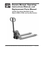
Owners Manual, Operating
Instructions Manual, and
Replacement Parts Manual
Lift-Rite Titan Series Hand Pallet Trucks
Models LCM50, LCU50, and Four-Way Versions
Lift-Rite, 5975 Falbourne Street, Mississauga, Ontario L5R3L8
Tel: Toll Free from USA: 1-800-558-6012; Tel: 1-905-456-2603 (Canada and International)
Fax: 1-905-456-1383 Owners Manual, Operating Instructions, and Replacement Parts Manual, Publications Number 1149374A ©2012
Dated 22 Jun 2012
This publication, 1149374A, applies to the Lift-Rite Titan Series Hand Pallet Trucks, Models LCM50,
LCU50, and Four-Way versions, and to all subsequent releases of this product until otherwise indicated in
new editions. Changes occur periodically to the information in this publication.
To order additional copies of this manual, part number 1149374A, contact your local authorized Lift-Rite
Sales and Service Center.
If you need assistance with your lift truck, contact your local authorized Lift-Rite Sales and Service Center.
To locate your Sales and Service Center, go to www.liftrite.com
©2012
Lift-Rite, 5975 Falbourne Street, Mississauga, Ontario L5R3L8
Tel: Toll Free from USA: 1-800-558-6012; Tel: 1-905-456-2603 (Canada and International)
Fax: 1-905-456-1383 Owners Manual, Operating Instructions, and Replacement Parts Manual, Publications Number 1149374A ©2012
Dated 22 Jun 2012
TABLE OF CONTENTS
DELIVERY INSPECTION
2
OPERATING INSTRUCTIONS
2
SAFETY PROCEDURES
3
DAILY INSPECTION
3
MAINTENANCE
4-5
TROUBLESHOOTING
6
PARTS
7-9
Hydraulic Assembly
7
LCM50 and LCU50 Chassis
8
LCM4W and LCU4W Chassis
8
Recycling Old Parts
9
WARRANTY
10
1
Lift-Rite, 5975 Falbourne Street, Mississauga, Ontario L5R3L8
Tel: Toll Free from USA: 1-800-558-6012; Tel: 1-905-456-2603 (Canada and International)
Fax: 1-905-456-1383 Owners Manual, Operating Instructions, and Replacement Parts Manual, Publications Number 1149374A ©2012
Dated 22 Jun 2012
SAFETY SHOES
Always wear safety shoes when working with hand pallet trucks.
PROTECTIVE GLASSES
When assembling or dismantling a hand pallet truck, protective
glasses must be worn to avoid personal injury.
OPERATOR’S RESPONSIBILITY
While operating a hand pallet truck, always wear safety equipment
and operate in a responsible manner to ensure a safe work area.
DELIVERY INSPECTION
Visually inspect hand pallet truck frame components and hydraulic unit for damage during
shipment by carrier. If damage is evident, notify delivering carrier immediately and file necessary
claims. Test the hand pallet truck pump for proper operation. If the hydraulic pump does not
respond to movement of the handle, an air lock may have developed during shipping. To
remedy this, go to the user friendly TROUBLESHOOTING guide in this manual.
OPERATING INSTRUCTIONS
(Read and understand prior to using this product)
To raise the load, push down on
the fingertip control. Pump the
handle to raise the load from the
floor.
To lower the load, pull up on the
fingertip control.
NOTE:
The neutral position disengages
the pump from the lifting
mechanism. This frees the handle,
which makes pulling loads easier.
In addition, the pump is not
subject to shock pressures while
the truck is in motion.
For free handle movement, place
the fingertip control in the neutral
position.
2
Lift-Rite, 5975 Falbourne Street, Mississauga, Ontario L5R3L8
Tel: Toll Free from USA: 1-800-558-6012; Tel: 1-905-456-2603 (Canada and International)
Fax: 1-905-456-1383 Owners Manual, Operating Instructions, and Replacement Parts Manual, Publications Number 1149374A ©2012
Dated 22 Jun 2012
SAFETY PROCEDURES
(Read and understand prior to using this product)
• Read and obey all labels on this product. If you have any questions about these, ask your
supervisor.
• Do not operate this hand pallet truck unless you are authorized and trained to do so.
• Never overload your hand pallet truck. Stay within its rated capacity.
• Do not operate this truck if damaged or not in proper working order.
• Distribute the load evenly on the forks. Do not concentrate loads at one point or load one fork
more than the other.
• When the load impairs visibility, the hand pallet lift truck should be pulled and not pushed.
• Always look where you are operating. Keep a clear view.
• Only handle loads on flat level surfaces. Do not use a loaded truck on inclines or declines.
• Never carry passengers.
• Never put your feet, hands, or any other body part under the frame assembly.
• Always yield right of way to pedestrians.
• Do not allow your hand pallet truck to drop from one level to another. Even a drop of 1 in.
(25 mm) more than doubles the effective load momentarily and results in a loading that can bend
or break components.
• Move loads only with the hand pallet truck in its lowest position.
• Always make sure that the load is stable before moving to eliminate the opportunity for load
shift.
• Use extreme care when rounding corners. Too fast a speed could cause a hand pallet lift truck to
tip. If loaded, the load could shift and fall.
• When not in use, fully lower the forks.
DAILY INSPECTION
At the start of your shift, check the items listed below. Report any malfunctions or unsafe conditions
to your supervisor. Do not use this product until it is repaired.
CHECK
POINTS
ACTION
Steering
Check full
rotation
Hydraulic
System
Check for
excessive oil
on exterior
and check for
function
Wheels
Chassis/
Handle
Lifting/
Lowering
Labels
Check for wear,
damage, and
remove debris
Check for
damage and
remove debris
Check for
function
Check for
readability
3
Lift-Rite, 5975 Falbourne Street, Mississauga, Ontario L5R3L8
Tel: Toll Free from USA: 1-800-558-6012; Tel: 1-905-456-2603 (Canada and International)
Fax: 1-905-456-1383 Owners Manual, Operating Instructions, and Replacement Parts Manual, Publications Number 1149374A ©2012
Dated 22 Jun 2012
MAINTENANCE
LUBRICATION
All pivot points are equipped with permanently lubricated bushings and bearings. To increase
bearing life, it is recommended that a few drops of light machine oil be applied at each pivot point
every 6 months. The thrust plate is equipped with three grease fittings. Apply grease under normal
conditions every 6 months.
PUSH BAR LINKAGE ADJUSTMENT
If the forks do not rise evenly at the tips, or the roller levers begin to drag on the floor, the following
adjustment is necessary:
LCM/LCU MODELS
•
•
•
•
Turn the hand pallet truck over so that the underside of the forks are accessible.
Remove one split pin (PL-20269) with 3/16 in. punch.
Remove pin (PL-20227) from bracket.
Adjust eyebolts (PL-20226). Turn counterclockwise to raise fork tips and clockwise to lower
fork tips.
• Replace pin (PL-20227) through eyebolt and replace split pin (PL-20269).
• When adjusted properly, the forks should be 2 in. (LCM)/1-3/4 in. (LCU) low height from
ground level in the lowered position.
HYDRAULIC SYSTEM
Your hydraulic system is maintenance free. Do not add hydraulic oil unless there is, or has been,
a leak. Use Premium HVI hydraulic oil or equal. Other oils, fluids, or solvents may damage your
hydraulic system. If you suspect additional oil is required, follow these steps:
1. Check for and fix any possible oil leaks.
2. Lower the truck and load with 600 lbs. (approximate).
3. Pump the truck to its maximum lift height.
4. Measure the vertical height of the exposed piston (215030) and refer to the chart below.
Distance (inches)
5-1/8 in.
4-3/4 in.
4-3/8 in.
4 in.
3-1/2 in.
3-1/8 in.
2-3/4 in.
2-3/8 in.
Oil to add (Fl. Oz.)
0
2.7
3.0
3.4
3.7
4.0
4.4
4.7
4
Lift-Rite, 5975 Falbourne Street, Mississauga, Ontario L5R3L8
Tel: Toll Free from USA: 1-800-558-6012; Tel: 1-905-456-2603 (Canada and International)
Fax: 1-905-456-1383 Owners Manual, Operating Instructions, and Replacement Parts Manual, Publications Number 1149374A ©2012
Dated 22 Jun 2012
MAINTENANCE (CONT.)
ADDING OIL (IF REQUIRED)
1.
2.
3.
4.
5.
Place and secure the truck on its right side (release valve facing the floor).
Pull up on the release lever (PL-40274BDM) and extend the lift piston fully.
Remove screw (221586) and add the amount of oil determined by the chart in step 4.
Reinstall screw (221586) but do not tighten. Leave a 1/32 in. gap.
Pull up on the release lever (PL-40274BDM) and collapse the lift piston until oil starts to
ooze from the screw.
CAUTION! - It is extremely important that step 5 is performed. Otherwise, air in
the pump can force out the wiper seal (20066). Take care when adding oil not to
introduce impurities into the hydraulic system.
6. Tighten the screw (221586) fully and return the truck upright.
5
Lift-Rite, 5975 Falbourne Street, Mississauga, Ontario L5R3L8
Tel: Toll Free from USA: 1-800-558-6012; Tel: 1-905-456-2603 (Canada and International)
Fax: 1-905-456-1383 Owners Manual, Operating Instructions, and Replacement Parts Manual, Publications Number 1149374A ©2012
Dated 22 Jun 2012
TROUBLESHOOTING
CONDITION
POSSIBLE CAUSE
ACTION
Pump does not lift load.
An air lock in the hydraulic
system.
Pull up on fingertip control and hold
while pumping the handle 8 to 10 times
to bleed air from the system.
Lifting, neutral, and lowering
do not function properly.
Chain anchor out of adjustment.
Turn nut (21094) on chain anchor
clockwise until pumping action, while in
neutral, does not raise forks.
Forks raise and sink with
pump action.
Dirt or foreign particle caught in
cone valve seat.
Pull up on fingertip control and hold
while pumping the handle 8 to 10 times
to purge the valve system.
Pump does not lift load to
complete raised height.
Pump is low on oil.
Check for and fix any leaks. Then add oil
as instructed in the MAINTENANCE
section.
Forks are not lowering
completely.
Push jam nut loose. Push bars
require adjustment.
Refer to Push Bar Linkage Adjustment
in the MAINTENANCE section.
6
Lift-Rite, 5975 Falbourne Street, Mississauga, Ontario L5R3L8
Tel: Toll Free from USA: 1-800-558-6012; Tel: 1-905-456-2603 (Canada and International)
Fax: 1-905-456-1383 Owners Manual, Operating Instructions, and Replacement Parts Manual, Publications Number 1149374A ©2012
Dated 22 Jun 2012
COMPLETE HYDRAULIC ASSEMBLY (PM-30277BN)
2
5
4
ITEM 60
16
3
6
17
1
18
19
7
8
20
21
22
9
23
25
10
24
28
27
26
11
29
30
12
34
32
36
31
35
33
13
14
38
37
42
43
39
49
41
45
40
48
47
46
15
50
51
53
57
52
58
56
55
54
50
ITEM
1
2
3
4
5
6
7
8
9
10
11
12
13
14
15
16
17
18
19
20
21
22
23
24
25
26
27
28
29
30
31
32
33
34
35
36
37
38
39
40
41
42
43
45
46
47
48
49
50
51
52
53
54
55
56
57
58
60
DESCRIPTION
COMPLETE HANDLE (ITEMS 2-10)
SPLIT PIN
CONTROL LEVER
CONTROL LEVER SLEEVE
CONTROL LEVER SPRING
CHROME BALL
CONTROL ROD ASSEMBLY
SPLIT PIN
AXLE
ROLLER W/BUSHING
AXLE
ADJUSTING NUT
LOCKING PIN
LOWERING ARM
COVER
LOCKING RING
SLEEVE
WASHER
SPRING
PISTON
PISTON
SEALING RING
LOCKING RING
SEALING
SEALING
SEALING
LOCKING PIN
BUSHING
SCREW
O-RING
WASHER
SPRING
VALVE CONE
SCREW (0VERLOAD)
O-RING (OVERLOAD)
SPRING (OVERLOAD)
GUIDE PIN (OVERLOAD)
BALL (OVERLOAD)
BALL
WASHER
O-RING
VALVE BODY
SPRING
U-RING
PISTON
LOWERING VALVE (COMPLETE)
BALL BEARING
LOCKING PIN
LOCKING PIN
THRUST PLATE
LOCKING PIN
GREASE NIPPLE
LOCKING RING
SPACER
(REQUIRED WITH 200965BT ONLY)
AXLE
BEARING
WHEEL COMPLETE
NYLON
POLY
POLY/STEEL
STEEL
HYDRAULIC UNIT
REBUILD KIT
QTY
1
1
1
1
1
2
1
1
1
1
1
1
1
1
2
1
1
1
1
1
1
1
1
1
1
1
1
2
1
1
1
1
1
1
1
1
1
1
1
1
1
1
1
1
1
1
1
1
2
1
1
1
2
2
PART NO.
PL-40276M
20105
PL-40274BDM
54140BT
218182
20065
215775
20461
47930
202755
7500086
21094
220312
215128
156623BT
20043
215803
215282
215156
215030
215286
21060
20642
20066
215866
215867
20014
215913
221586
24213
219201
39106
223935
221232
22032
221227
221231
22055
20065
215288
22032
7500112
47071
7500100
7500116
7518604
213056
220312
PL-20269
245552
21737
27662
20019
161637
1
4
220310
22226
2
2
2
2
1
1
251189
160422BT
200965BT
160433
PM-30277BN
243772
7
Lift-Rite, 5975 Falbourne Street, Mississauga, Ontario L5R3L8
Tel: Toll Free from USA: 1-800-558-6012; Tel: 1-905-456-2603 (Canada and International)
Fax: 1-905-456-1383 Owners Manual, Operating Instructions, and Replacement Parts Manual, Publications Number 1149374A ©2012
Dated 22 Jun 2012
MODELS LCM50 AND LCU50 CHASSIS DIAGRAM
ITEM
1
1
2
2
14
5 4
6
13
3
23
16
4
25
12
14
5
7
9
19
9
9
6
23
4
17
9
13
12
23
3
10
11
5
6
MODELS LCM4W AND LCU4W
CHASSIS DIAGRAM
7
9
10
DESCRIPTION
CHASSIS
(SPECIFY LENGTH AND WIDTH)
- FOR LCM50
(2 IN. LOW PROFILE)
- FOR LCU50
(1.75 IN. ULTRALOW PROFILE)
AXLE
- (INCLUDES BOLT SLEEVE & NUT)
LOAD ROLLER (LCM50 & LCM4W)
- STEEL
(W/BEARING & SLEEVE)
POLYURETHANE
(W/BEARING & SLEEVE)
LOAD ROLLER (LCU50 & LCU4W)
- STEEL
(W/BEARING & SLEEVE)
BEARING (LCM50 & LCM4W)
- FOR STEEL & POLYURETHANE
LOAD ROLLER
BEARING (LCU50 & LCU4W)
- FOR STEEL LOAD ROLLER
SPACER WASHER
LEVER ARM ASSEMBLY
(INCLUDES BUSHINGS)
- FOR LCM50 & LCM4W
- FOR LCU50 & LCU4W
FORK PIN
BUSHING
PUSH BAR
- FOR LCM50 & LCM4W
(SPECIFY LENGTH)
11
12
13
14
16
21
2
14
5 4
6
13
22
9
4
14
9
25
12
9
17
13
10
12
23
11
5
21
7
9
19
17
19
3
23
6
23
22
23
25
- FOR (LCU50 & LCU4W)
(SPECIFY LENGTH)
EYE BOLT
(INCLUDES NUT & BUSHING)
SPLIT PIN
THRUST PLATE SHOULDER PIN
BUSHING
TORSION BAR
- 20.5 IN. WIDE (LCM50 & LCU50)
- 27 IN. WIDE (LCM50 & LCU50)
EYE BOLT PIN
BULKHEAD PIN
CHASSIS (SPECIFY LENGTH &
WIDTH)
- FOR LCM4W
(2 IN. LOW PROFILE)
- FOR LCU4W
(1.75 IN. ULTRALOW PROFILE)
TORSION BAR
- 33 IN. WIDE(LCM4W & LCU4W)
BUSHING
SPLIT PIN
QTY
PART NO.
1
PM-30200
1
PM-30200U
2
PM-10215
2
PM-10210S-B
2
PM-10210P-B
2
PM-10210U-B
4
PM-10214S
4
4
PM-10214P
PL-10216
2
2
2
6
PM-30212
PM-30212U
PM-10219
PL-20206
2
PM-20224X_
and 1125308-_
2
1125142-_
2
6
2
2
PL-20226
PL-20269
PL-30207
PL-20203A
1
1
2
2
PM-30201
PM-30202
PL-20227
PL-20204
1
PF-30200
1
PF-30200U
1
6
2
PF-30203
PL-20226A
PM-20269
8
Lift-Rite, 5975 Falbourne Street, Mississauga, Ontario L5R3L8
Tel: Toll Free from USA: 1-800-558-6012; Tel: 1-905-456-2603 (Canada and International)
Fax: 1-905-456-1383 Owners Manual, Operating Instructions, and Replacement Parts Manual, Publications Number 1149374A ©2012
Dated 22 Jun 2012
RECYCLING YOUR OLD LIFT-RITE PARTS
Chassis
Steel
Roller suspension
Steel and cast iron
Bushings
Brass
Grease fittings
Steel
Rollers
Nylon, polyurethane, steel
Hydraulic body
Cast iron
Thrust plate
Cast iron
Handle
Steel
Wheel
Nylon, polyurethane, steel
Bushings
Brass
Hydraulic oil
Disposal in accordance with local regulations
Assembly parts
Steel, brass, nylon
9
Lift-Rite, 5975 Falbourne Street, Mississauga, Ontario L5R3L8
Tel: Toll Free from USA: 1-800-558-6012; Tel: 1-905-456-2603 (Canada and International)
Fax: 1-905-456-1383 Owners Manual, Operating Instructions, and Replacement Parts Manual, Publications Number 1149374A ©2012
Dated 22 Jun 2012
HAND PALLET TRUCK WARRANTY
The Lift-Rite Titan Series Hand Pallet Trucks, Models LCM50 and LCU50 versions, are warranted against defects
in materials and workmanship for a period of two (2) years for the hydraulic pump, one (1) year for the truck
chassis, and six (6) months for wearable components. All periods begin from date of installation.
Wearable Components include but are not limited to:
• Wheels, Rollers, and Bearings
• Oilite Bearings and Bushings
Components found to be defective by an authorized Lift-Rite Sales and Service Center during the warranty
period will be replaced or repaired as indicated above. Replacement components installed during the defined
period set forth above, are warranted for the balance of the applicable truck warranty period, or 90 days,
whichever is longer. Additionally, freight charges for parts involved in the replacement or repair of a defective
component will be paid by Lift-Rite, provided that the replacement or repair is made by an authorized Lift-Rite
Sales and Service Center. Labor or miscellaneous costs involved in the replacement of any components
determined to be defected are not covered. Local taxes, if any, are excluded.
This warranty is void in the event of defects or damage caused by misuse, abuse, or accident. Any truck used
under adverse conditions, such as fish, meat or poultry processing plants, tanneries, freezer applications, or
any other application where the unit is operating in water or subjected to fluid or chemicals is NOT covered
under any warranty.
This warranty does not cover oil leaks, adjustments, or loose hardware.
Lift-Rite reserves the right to make changes and improvements in design without making changes to
previously manufactured vehicles.
Notwithstanding any other language contained herein, this warranty is expressly voided without any further
notice if any modification is made to the Lift-Rite equipment, or if additional components or devices are added
to the Lift-Rite equipment, without prior approval having been granted in writing by Lift-Rite.
THIS WARRANTY IS IN LIEU OF ALL OTHER WARRANTIES, EXPRESSED, IMPLIED, OR STATUTORY.
THERE ARE NO WARRANTIES OF MERCHANTABILITY OR FITNESS FOR A PARTICULAR PURPOSE.
In no event shall Lift-Rite be liable for incidental, special, or consequential damages.
10
Lift-Rite, 5975 Falbourne Street, Mississauga, Ontario L5R3L8
Tel: Toll Free from USA: 1-800-558-6012; Tel: 1-905-456-2603 (Canada and International)
Fax: 1-905-456-1383 Owners Manual, Operating Instructions, and Replacement Parts Manual, Publications Number 1149374A ©2012
Dated 22 Jun 2012
Lift-Rite, 5975 Falbourne Street, Mississauga, Ontario L5R3L8
Tel: Toll Free from USA: 1-800-558-6012; Tel: 1-905-456-2603 (Canada and International)
Fax: 1-905-456-1383 Owners Manual, Operating Instructions, and Replacement Parts Manual, Publications Number 1149374A ©2012
Dated 22 Jun 2012