1
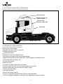
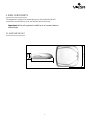
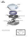
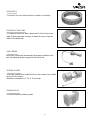
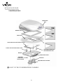
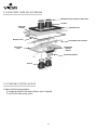
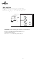
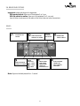
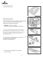
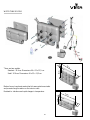
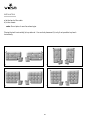
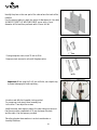
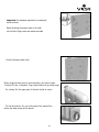
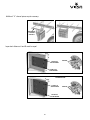
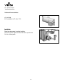
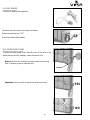
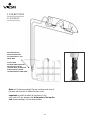
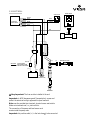
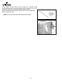
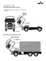
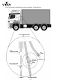
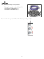
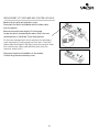
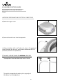
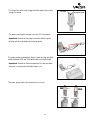
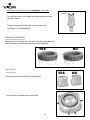
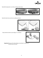
ECOLOGICAL COOLERS
ECON
Installation Manual
www.viesa.ca / 1-888 438-8444
IMPORTANT
Installation requires an experienced mechanic with specific knowledge in the installation of
the VIESA Ecological Cooler. Installation, disassembly, repairs and maintenance
must be performed by an Authorized Installer. Authorized Installer must use proper
protective equipment when installing the system.
Improper installation or use of unauthorized parts can cause malfunctions, loss of battery life
or other consequences which may result in serious injury.
Manufacturer or Distributor will not be responsible for injuries or damages resulting from
misuse of equipment, use contrary to operating instructions or installation by any person
other than an Authorized Installer.
Information contained in this manual is subject to change. Manufacturer reserves the right,
without notice, to make changes in equipment design or components as progress in
engineering, manufacturing or technology may warrant.
World-wide Patents
VIGIA is a trademark of Col-Ven S.A.
Index
INSTALLATION MANUAL
1- ECOLOGICAL COOLER ...............................................................................................................5
1.1- LOCATION OF PARTS AND COMPONENTS ..........................................................................6
1.2- TECHNICAL CHARACTERISTICS ................................................................................................6
2- MAIN COMPONENTS
.............................................................................................................7
2.1- EVAPORATOR UNIT .......................................................................................................................7
2.2- UPHOLSTERY COVER AND ACCESSORIES ............................................................................14
2.3- POWER AND CONTROL MODULE .........................................................................................14
2.4- BOARD INDICATIONS.......................................................................................................17
2.5- UPHOLSTERY COVER ..................................................................................................................18
2.6- WATER TANK ................................................................................................................................20
2.7- WATER TANK SUPPORT (OPTIONAL) .................................................................................26
2.8- WATER PUMP .................................................................................................................................28
2.9- LEVEL SENSOR ...............................................................................................................................29
2.10- WATER PUMP COVER ...............................................................................................................29
3- CONNECTIONS ...........................................................................................................................30
3.1- HYDRAULIC ..................................................................................................................................30
3.2- ELECTRICAL ..................................................................................................................................31
4- UNITS WITH TILT CABINS ....................................................................................................33
5- RECOMMENDATIONS TO THE INSTALLER .....................................................................35
6- GENERAL MAINTENANCE .......................................................................................................35
7- REPLACEMENT OF THE MAIN COMPONENTS ..............................................................37
8- FAILURE LOCATION GUIDE
.............................................................................................40
1- ECOLOGICAL COOLER
Function
VIESA Econ is a roof mounted cab cooler that delivers cool air to the truck's cabin
using evaporative cooling and without running the truck's engine.
Operation
Cooling is generated by vaporized cool water delivered by a self-contained
electrical motor. During operation it only consumes water and it makes no use of
internal combustion engines, nor does it use chemical coolants or emit gases into
the atmosphere. The unit is equipped with a water pump located in an auxiliary
tank which takes water to the evaporator. A biturbo blower pushes the exterior
air to the interior of the truck forcing the air through the evaporator and
therefore cooling the warm air. The exceeding water backs to the water tank.
Application
Applied to any vehicle with an operating voltage of 12 V.
5
1.1- LOCATION OF PARTS AND COMPONENTS
EVAPORATOR UNIT
UPHOLSTERY COVER WITH
DISPLAY CONSOLE
ELECTRICAL AND
HYDRAULIC CONNECTIONS
WATER TANK
1.2- TECHNICAL CHARACTERISTICS
Aerodynamic external design
Evaporator unit cover with UV protection
Adjustable upholstery cover.
8- speed turbo blower
Distribution air ducts with airtight closure.
Turbo blower with sealed motor mounted on bearings
Designed and manufactured according to EMC (electromagnetic compatibility norm).
32-litre water tank with pump cover
Anti-spill water system
Water level sensor
Low water lever pump disconnection and alarm
Protection system for short-circuit in the pump and its connections
Automatic system disconnection under low battery voltage
Protection for high voltage
Fused main feed cable
Protection for polarity reversal
8 A per hour average consumption with turbine at maximum speed
2 to 5 liter average consumption of water per hour, depending on ambient humidity
6
2- MAIN COMPONENTS
The equipment consists of an evaporating unit, electrical and hydraulic
connections, an upholstery-cover and a water tank with pump.
Important: Vehicle with equipment installed must not exceed maximum
allowed height
21 CM.
75 CM.
2.1- EVAPORATOR UNIT
82 CM.
7
EVAPORATOR
UNIT COVER
EVAPORATOR
EVAPORATOR TRAY TANK
BITURBO BLOWER
POWER MODULE
BASE
COVER OF THE EVAPORATOR UNIT
8
EVAPORATOR
Composed of two even distributed layers of special wood shavings.
EVAPORATOR TRAY TANK
This element works as a water deposit and it collects the excess
water that the evaporator receives. It allows the return of excess
water to the water tank.
LEVEL SENSOR
Its function is to monitor permanently the presence of water in the
tank, activating the water pump when the level is low.
BITURBO BLOWER
It has two turbines which absorbs the air that comes from outside
forcing it to the interior.
Maximum consumption is 7,5 A. in 12 volt-units.
POWER MODULE
It controls the biturbo blower speed.
9
INSTALLATION PROCDURE
Units Without Hatch
EVAPORATOR
UNIT
YES
WEATHER STRIP
NO
UNIT’S ROOF
STEEL FRAME FOR ROOF WITHOUT HATCH
PLASTIC NUT FOR UPHOLSTERY COVER
ADJUSTING SCREWS FOR
THE EVAPORATOR UNIT
WASHER
UPHOLSTERY COVER
ADJUSTING
UPHOLSTERY
COVER SCREWS
AIR GRILLE
ADJUSTING GRILLE SCREWS
DO NOT CUT ROOF OVER REINFORCING CHANNELS
10
a) Use Viesa`s Interior and Exterior Templates to cut the roof openings.
a.1) Determine the suitable place where the evaporator unit will be placed.
a.2) Mark the openings to be cut.
a.3) Check from the inside that no reinforcement channels or electrical wires will be cut.
a.4) Cut the roof and shave any roughness.
Note: When cutting, be carefull not to make right angles on the
the corners. Corners must be round (see detail) in order to avoid
future roof fissures.
Important: If the roof surface is a thin metal sheet,
a 1cm. fold upwards has to be made all around the perimeter.
b) Glue the weather strip to the base of the evaporator.
c) Apply silicone glue on the underside of weather strip so as to avoid
water filtration.
d) Place and affix the evaporator unit to the roof.
e) Place the steel frame in the interior against the ceiling.
f) Use the 4 screws (changeable length in accordance with the
thickness of the ceiling) and tighten until the weather strip is
compressed to 10 mm. approximately.
DIRECT PLASTIC WASHERS
INWARDS
Note: If there is enough space, use a nut and locking nut
between the underside of the roof and the base of the evaporator unit.
Important: In roofs without reinforcements some support must be
provided in order to maintain rigidity to the cab.
11
Units with Hatch
EVAPORATOR
UNIT
WEATHER
STRIP
UNIT’S ROOF
NUTS
ADJUSTABLE ROOF SUPPORT
PLASTIC NUT FOR UPHOLSTERY COVER
ADJUSTING SCREWS FOR
THE EVAPORATOR UNIT
WASHER
UPHOLSTERY
COVER
AIR GRILLE
ADJUSTING UPHOLSTERY
COVER SCREWS
ADJUSTING GRILLE SCREWS
a) Remove the original hatch.
b) Glue the weather strip to the base of the evaporator.
Make sure weather strip will sit on the roof, not over the opening.
c) Apply silicone glue on the underside of weather strip so as to avoid
water filtration.
d) Place and affix the evaporator unit to the truck’s roof.
12
e) Place the adjustable roof supports in the interior against the ceiling.
f) Use the 4 screws (changeable length in accordance with the
thickness of the ceiling) and tighten until the weather strip is
compressed to 10 mm. approximately.
Note: If there is enough space, use a nut and locking nut
between the underside of the roof and the base of the evaporator unit.
Note: If the adjustable supports are to long, cut them at their ends.
Important: In roofs without reinforcements some support must be
provided in order to maintain rigidity to the cab.
WEATHER STRIP
BASE OF THE EVAPORATOR UNIT
ADJUSTING SUPPORT
ROOF
OR REINFORCEMENT
MINIMUM: 20 MM
WEATHER STRIP
NUT AND LOCKING NUT
TIGHTEN
4 SCREWS IN ROTATING SEQUENCE
13
UP TO THE INDENT
DIRECT PLASTIC NUTS
INWARDS
2.2- UPHOLSTERY COVER AND ACCESSORIES
WEATHER STRIP FOR AIR DUCT AND GRILLE
AIR DUCT
REDUCING
SUPPORT
WEATHER STRIP
WEATHER STRIP
ADJUSTABLE ROOF SUPPORT
UPHOLSTERY
COVER
POWER AND
CONTROL
MODULE
TOUCH-PAD CONTROL
GRILLES
2.3- POWER AND CONTROL MODULE
It allows the following operations:
To change the speed of the biturbo blower (up to 8 speeds)
To control the water pump cycles.
14
TECHNICAL CHARACTERISTICS
a) Protection for polarity reversal.
b) Protection for high voltage
c) Short-circuit protection in the water pump and in the biturbo fan and/
or in its corresponding electrical connections.
d) Automatic disconnection due to lack of water in the tank.
e) Working tension: 12 volts
f) Auto switch off for low battery tension
Note: voltage is monitored at the battery terminals.
CONTROL OF THE WATER
The module controls the operation of the pump cycle. It is showed in
the following chart:
OPERATING
WATER PUMP
± 35 SECONDS
BETWEEN 14
AND 30
SECONDS
WATER PUMP
OFF
OPERATING
WATER PUMP
± 7 MINUTES
IGNITION
SELECTABLE
SEE WATER CYCLE SETTING
LOW WATER LEVEL SENSOR
It monitors the presence of water in the tank; if there is a lack of water,
it informs the operator with a red LED indication and it
stops the operation of the water pump automatically.
Note: After replenishing the water tank the alarm will stop after approximately 3 minutes.
15
Water Cycle Setting
Very important: It is necessary to select one of the settings
for the water cycle and according to the height of the water column.
Without this setting the power and control module will not work.
Evaporator Unit
WATER COLUMN
Water
column
0.40-1.20 mts.
1.25-2.00 mts.
Water
tank
More than 2.00
mts.
USE KEY N°
WORKING TIME
20 Sec.
25 Sec.
30 Sec.
35 Sec.
(Do not use)
40 Sec.
(Do not use)
Important: to change the setting after installation proceed as follows:
Remove the fuse or disconnect the main positive wire (+)
Activate the corresponding key
Place the fuse or connect the main positive cable (+)
16
2.4- BOARD INDICATIONS
Important: before switching on the equipment:
With parked vehicle: Open one of the windows 2 to 3 cms.
With the vehicle in motion: Open one of the windows 2 to 3 cms and
close all other air entrances to the cabin so that hot air does not enter from exterior.
BOARD
SYSTEM ON-OFF
TURBO FAN SPEED
SWITCH
CONTROL TO HIGHER
TURBO FAN SPEED
CONTROL TO LOWER
TURBO FAN
SPEED
INDICATOR
1, 2 AND 3
4, 5 AND 6
7 AND 8
REMOTE
CONTROL
RECEPTOR
WATER PUMP
ON-OFF SWITCH
WATER TANK INDICATOR
EMPTY WATER
TANK ALARM
(WATER PUMP
TURNS OFF
AUTOMATICALLY)
Note: Keys must be held pressed for ± 1 second.
17
SLOW FLASHING:
CONNECTED
FAST FLASHING:
OPERATING
2.5- UPHOLSTERY COVER
INSTALLATION PROCEDURE
1- Insert the weather strips into the evaporator`s base openings and
push the air ducts (burr up) through the weather strips
making pressure until they are firmly placed.
Important: Cut the air ducts if needed.
Air ducts 240 mm high can be ordered for very thick ceilings.
CUT
2- Attach the command and control module to the upholstery
cover inserting the 3 locking pegs into their holes. Insert the
ribbon cable as indicated in the figure (raise the connector head
first, introduce the ribbon cable and then push down the
connector head to lock).
3- Locate the switch commanding the water cycle and set it
according to the water column height.
(See Water Cycle Setting before)
LOCKED
UNLOCKED
4- Connect the electrical installation to the command
and control module.
18
Note: Tie and stick the electrical installation to the upholstery
cover with the provided tie.
STICK THE
AUTOADHESIVE
6- Place the upholstery cover with the display oriented to the
front of the cabin.
7- Affix the upholstery cover with the 4 screws (without
tightening.
8- Introduce the air grilles with their weather strips.
9- Fasten the air grilles to the upholstery cover with the screws,
in the indicated sequence.
19
CONN
ECT
10- Tighten, without forcing, the 4 upholstery screws until
covering the original upholstery without gaps.
2.6- WATER TANK
Placement
20
WATER TANK MODELS
64
cm
.
52 cm.
There are two models:
Standard: 32 litres. Dimensions: 64 x 52 x 13,5 cm.
Small: 20 litres. Dimensions: 64 x 35 x 13,5 cm.
.
5
3,
cm
1
Made of a non translucent material which assures darkness inside
and prevents fungi formation on the interior walls.
Resistant to vibrations and rapid changes in temperature.
cm
.
13
,
5
cm
.
35 cm.
64
21
INSTALLATION
a) at the back of the cabin.
b) in the chassis.
note: Do not place it near the exhaust pipe .
Placing the tank horizontally (a) is preferred. Use vertical placement (b) only if not possible to place it
horizontally.
a)
b)
a)
b)
22
VERY IMPORTANT:
NEVER APPLY TANK TO CABINS WITHOUT REIFORCEMENTS
INSIDE
REINFORCEMENTS
TRUCK CABIN
WATER TANK SUPPORT PLATE
YES
NO
THREADED RIVET
(PUT IT IN THE LINE
OF WELDINGREINFORCEMENT
CHANNEL)
POLYESTER
FOAM WASHER
ALUMINUM SPACER
WASHER
GROWER
WASHER
SCREW
23
Identify the place on the rear part of the cabin where the tank will be
installed.
Use the support plate to mark the points of attachment to the cabin.
ALLWAYS OVER THE WELDING LINES prove with a 5 mm.
diameter drill bit and then perforate with a 9 mm. drill bit.
9 mm.
If using neoprene rivets, use a 12 mm. drill bit.
Neoprene rivets are used in units with fibreglass cabins.
12 mm.
Important: When using the 5 or 9 mm. drills bits, use a depth stop,
to prevent damaging the inside upholstery.
Introduce and affix the threaded rivets provided.
For neoprene rivets insert them (manually) up
to the brim. Then adjust the screws.
Install the water tank support plate to the cabin taking into account
that there must be a separation of 10 mm. between the plate
and the cabin. Use the spacers provided.
Place the polyester foam washers in order to avoid water or
humidity filtrations.
24
Important: Use adequate separators to compensate
uneven surfaces.
Before attaching the support plate to the cabin,
set the tank's fixing screws and washers provided.
Attach the support plate firmly.
When using the water tank on vertical position; you have to make
3 holes of 22 mm. in diameter. Plug original holes with provided plugs.
- For venting: On the upper part of the tank and at its center.
- For the level sensor: On one of the ends of the marked line
where the water pump will be placed.
25
- For draining , at the bottom of the water tank and on the
same side of the water tank cap.
Important: Remove shavings.
SEAM
NO
YES
INSERT
DRAIN PLUG
Place the water tank on the support plate and affix with the provided screws and washers.
Once the tank has been installed, cut the cord from the evaporator
containing hoses and wires. See electrical and hydraulic diagrams
in order to assess their length.
2.7 - WATER TANK SUPPORT (OPTIONAL)
Depending on the vehicle, the water tank support can be placed
parallel or perpendicular to the chassis frame.
Never drill the frame’s flange.
26
Additional “U” channel pieces
. may be necessary.
ADDITIONAL
U-SHAPED
SUPPORT
Important: distances A and B must be equal.
SMALL TANK
90 mm
.
A
POINTS OF
ATTACHMENT
REMOVE
POINTS OF
ATTACHMENT
B
STANDARD TANK
90 mm
.
A
POINTS OF
ATTACHMENT
B
27
POINTS OF
ATTACHMENT
REMOVE
2.8- WATER PUMP
Technical Characteristics
a) Centrifugal
b) Consumption in 12 volts: 3.1 A.
Installation
Place the water pump in vertical postilion.
Insert the pump’s nipple into the water tank cap with hole.
Use the rubber gasket.
28
2.9- LEVEL SENSOR
Controls the water pump operation.
Introduce the level sensor according to the figure.
Keep the marked arrow “UP”.
Use the provided rubber gasket.
2.10- WATER PUMP COVER
To place the water pump cover insert first one of the holes in the
water tank pin an then, manually, insert the second hole.
Note: Make sure not to obstruct the water pump cover draining
hole. If necessary, make an additional hole.
DRAINAGE
Important: Don't use tools to remove the water pump cover.
YES
NO
29
3- CONNECTIONS
3.1- HYDRAULIC
THIS VALVE MUST BE
INSTALLED BELOW THE
THE UPPER EDGE OF THE
WATER TANK.
IN TILT CABINS
OR WATER TANKS INSTALLED
ON THE TRUCK CHASSIS
THE VALVE MUST BE INSTALLED
AT MORE THAN 1 M BELOW
THE EVAPORATOR'S LOWER EDGE.
Note: cut the tubes accordingly. The grey cord wrap must cover all
the hoses and wires until it reaches the pump cover.
Important: to install the elbow (for ventilation) in the
tank, make a 22 mm. diameter hole in the center of the top the
tank (remove shavings). Use the elbow provided.
30
3.2- ELECTRICAL
POWER MODULE
5-WAY SOCKET
POWER AND
CONTROL MODULE
YELLOW
BLACK
BLACK
BROWN
BROWN
RED
BLACK
(+)
(-)
BLACK
RED
RED
THE FUSE HOLDER
MUST REMAIN OUTSIDE
THE BATTERY COMPARTMENT
2 x 1,50 + 2 x 0,50
RED
BLACK
YELLOW-R or LIGHT BLUE
YELLOW
BLACK
(+)
(+)
RED
IMPORTANT:
(-)
BLACK
FUSE 15A
CURRENT BREAKER
2x4
RED
BITURBO BLOWER
21
(-)
(+)
(-)
BATTERY
WATER LEVEL
SENSOR
(POLARITY FREE)
21
WATER PUMP
Very Important: The fuse must be installed at the end.
Important: In ADR (dangerous goods Transportation), encase and
protect the electrical wiring in approved fire-proof material.
Note: use the provided wire terminals, terminal covers and sockets.
Solder wire terminals and / or joints with tin.
The connection of the pump and level sensor must
remain inside the pump cover.
Important: the positive cable (+) is the last element to be connected.
31
ANTIPARASITIC FILTER
ATTACHING THE ELECTRICAL AND HYDRAULIC CONNECTIONS
Use the self-adhesive tie bases and plastic ties provided to
attach the electrical and hydraulic connections from the evaporator
down to the water tank.
Note: Clean the surface where the adhesive will be placed.
30 CM
32
4- UNITS WITH TILT CABINS
a) With Water Tank Applied to the Cabin.
Note: The power supply must be direct from the battery or the
main switch.
SET OF
ELECTRICAL
AND HYDRAULIC
CONNECTIONS
ELECTRICAL
INSTALLATION
ORIGINAL MAIN SWITCH
b) With Water Tank Applied to the Chassis
SET OF ELECTRICAL AND
HYDRAULIC CONNECTIONS
DUAL RESTRICTION
VALVE
QUICK CONNECTION HOSE
ELECTRICAL
INSTALLATION
33
Wires to the water tank and battery must be extended. See detail below.
TO THE EVAPORATOR UNIT
DUAL
RESTRICTION VALVE
RED
BLACK
YELLOW
YELLOW-R
RED
BLACK
QUICK CONNECTION
TO THE WATER
PUMP
TO THE WATER PUMP
AND LEVEL SENSOR
34
TO THE BATTERY
5- RECOMMENDATIONS TO THE INSTALLER
. cooling.
- Wet the evaporator immediately after installation in order to fast start
- Clean the working area.
- Provide the owner with the Viesa User's Manual and warranty information.
- Explain the user the operation and maintenance of the equipment in detail.
- Explain to the user that, BEFORE SWITCHING ON THE UNIT
one window must have a 3 cm opening and all other vents must be closed.
This opening will allow hot air to be expelled from the interior.
6- GENERAL MAINTENANCE
The equipment will delay in cooling until the evaporator is totally wet.
Do not use fuses higher than 15 Amp.
The equipment will deactivate automatically due to low tension so
as to prevent damages to the battery.
Use only clean water.
Foresee replenishment of water taking into account that the
equipment consumes between 2 and 5 litres per hour depending on
the ambient temperature.
During short stops leave the equipment on so as to keep the cabin
fresh.
System must be turned off when exhaust fumes or toxic particles
could enter the cab through the system.
VIESA SCENTED FLUID (EVERY 200 HOURS OF USE)
When performing maintenance of the equipment or if
the evaporator unit's cover or the upholstery cover are removed,
the system MUST NOT BE SWITCHED ON and
you must not switch it on with any of these elements removed.
Keep the tank clean. Every 200 hours of use
- Drain all the water from the tank by removing the drain
.
plug.
- Rinse with clean water thoroughly.
- Pour one bottle of Viesa Scented Cleansing Fluid.
- Fill-up the tank with clean water.
Each 6 months change the package of granulated Calfa Bas crystals.
Do not use chemical products to clean the control panel.
35
GRANULATED CALFA BAS EACH 6 MONTHS
Every 2 months or according to working conditions:
- Submerge the evaporator in water with bleach (1).
- Clean the grids of the air entrances (2).
- Clean the filter of the collector tray (3).
Reconnect water returning hose to the filter of the collector tray according to the figure.
3
36
7- REPLACEMENT OF THE MAIN COMPONENTS
REPLACEMENT OF THE MOTOR OF THE BITURBO BLOWER
Remove the cover of the evaporator unit fixed with 5 screws.
Remove the evaporator.
Remove the two turbines' covers taking away the 8 screws.
Remove the 4 screws of the blower mounting bracket and remove it.
Replace the motor making the corresponding electrical
connection.
Put back the motor's mounting bracket and adjust.
Important: Before tightening the bracket, center the motor correctly
so that the turbines do not on rub the sides.
Put back the two turbine covers.
Place back and adjust the cover of the evaporator unit.
37
REPLACEMENT OF THE POWER MODULE
Remove the cover of the evaporator unit.
Remove the 2 screws holding the power module to the base.
Change the power module and reconnect.
Reinstall the cover of the evaporator unit.
REPLACEMENT OF THE EVAPORATOR
Remove the upper cover, after removal of the 5 screws.
Remove and replace the evaporator (disconnect
reconnect the 9 x 15 cm hose).
Place back the upper cover fixing it with the 5 screws.
38
REPLACEMENT OF THE POWER AND CONTROL MODULE
Remove the air grilles and upholstery cover.
Disconnect the electrical installation and the ribbon cable
from the module.
Remove the module unlocking the 3 locking pegs.
Locate the switch commanding the water cycle in the new
module and set it. (See Water Cycle Setting before)
Put the new command and control module to the upholstery
cover inserting the 3 locking pegs into their holes. Insert the
ribbon cable as indicated in the figure (raise the connector head
first, introduce the ribbon cable and then push down the
connector head to lock).
Reconnect the electrical installation to the module.
Put back air grilles and upholstery cover.
39
LOCKED
UNLOCKED
8- FAILURE LOCATION GUIDE
EQUIPMENT WITH LOW EFFICIENCY
Check:
WATER PUMP PERFORMANCE AND ELECTRICAL CONNECTIONS
a) Remove the upper cover.
b) Remove the water hose from the evaporator.
c) Using a container with a cm3 scale on it, turn on the pump and
collect the water for one cycle, which should be between 800 cm3
(minimum) and 1500 cm3 (maximum).
If the water collected is below the minimum, check that:
YES
The evaporator hose is not obstructed, bent or kinked.
The switch commanding the water cycle is properly set.
(See Water Cycle Setting before)
40
NO
The restriction valve is not clogged and that water flows freely
trough the outlet.
OUTLET
(NO RESTRICTION)
CLOGGED
The water pump supply voltage is correct: 9.8 V minimum.
Important: Measure at the pump's connector with the pump
working and the turbo blower at maximum speed.
The water pump consumption (Amp) is between the specified
values: between 2.0A and 4.0A (with water running through).
Important: Remove the fuse and measure at the fuse box while
the pump is running and the biturbo blower is off.
The water pump electrical connections are correct.
BLACK (-)
NO
(+)
41
RED (+)
YES
RED (+)
(-)
BLACK (-)
(+)
(-)
If the water collected is above the maximum, check that:
(NO RESTRICTION)
OUTLET
CLOGGED
The restriction valve is not clogged and that water returns freely
trough the outlet.
The switch commanding the water cycle is properly set.
(See Water Cycle Setting before)
EVAPORATOR ASSESSMENT
Manually pull up the evaporator and with the water pump working,
check that water is distributed evenly around the evaporator.
YES
NO
VENTILATION
YES
Check that the air grilles have their weather strips.
Check that the air intakes are not obstructed.
42
NO
Verify that the evaporator is not dirty or lacking wooden chips.
YES
NO
YES
NO
Verify that electrical connections are rightly performed.
Verify the biturbo blower input voltage: 9.5 V minimum.
Important: Measure at the biturbo blower pins and when it is working and
the water pump is working.
43
PROBLEM
The indicators are ok, but the
equipment has low efficiency.
POSSIBLE CAUSES
HYDRAULIC
1- Inverted electrical connections
of water pump/s.
2- Evaporator 9 x 15 cm hose
blocked.
3- Evaporator placed upside down
4- Blocked holes at the water
distributor of the evaporator.
5- Dirty evaporator.
6- Water pump damage.
7- Faulty power and control
module.
8- Water Cycle Switch with
wrong setting.
When the equipment is on, water
enters by the air grilles and/or it
spills through the ceiling.
SOLUTIONS
HYDRAULIC
1- Connect correctly: Red (+)
and black (-).
2- Modify.
3- Place the evaporator with the
hose connector upwards.
4- Replace the evaporator.
5- Clean and/or replace the
evaporator.
6- Replace the water pump.
7- Replace the power and control
module.
8- Reset Water Cycle Switch
according to water column height.
VENTILATION
9- Air grilles without weather
strips.
10- Blocked air entrances of the
base of the unit.
11- Faulty blower.
VENTILATION
9- Put strips to the air grilles.
1- Incorrectly oriented holes
of the water distributor of the
evaporator.
2- Blocked dual restriction valve.
1- Replace the evaporator.
3- Blocked return hoses.
4- Blocked PVC filters in the
evaporator's tray.
5- Water column less than 40 cm.
3- Clean hoses or change path.
4- Clean PVC filters.
6- Water Cycle Switch with
wrong setting.
6- Reset Water Cycle Switch
according to water column height.
44
10- Clean the air entrances.
11- Replace the motor of the
blower.
2- Clean or replace the valve.
5- Place the tank lower.
SOLUTIONS
SOLUTIONS
PROBLEM
POSSIBLE CAUSES
The equipment works well, but
the fuse burns out continuously.
1- Short-circuit in the blower or
in its connections.
2- Short-circuit in the water
pump or its connections.
3- Damaged power wire.
1- Replace the blower or repair.
Water pump operation not
showing on display.
(blower works at one speed only)
1- Inverted electrical connections
to battery.
1- Connect red wire to +
black to -
2- Faulty power and control
module.
2- Replace the command and
control module.
Power module burns out.
1- Seized biturbo blower.
1- Replace biturbo blower motor.
Pump cycles are not right ones.
1- Water Cycle Switch with
wrong setting.
1- Reset Water Cycle Switch
according to water column height.
Blower at its maximum speed
cannot be turned off.
1- Faulty power module.
Blower works, display shows
normal operation but the
pump doesn’t work.
1- False contact and/or
disconnection of the ribbon cable.
(control and command module)
1- Replace the power module.
Check the free spinning of the
blower.
1- Repair and/or connect.
The speeds do not match the
display indications or they do not
change.
2- Replace the water pump or
repair.
3- Locate, repair and seal
correctly.
2- False contact and/or
disconnection of the water pump.
2- Repair and/or connect.
Tin terminals of the water pump.
3- Faulty control and command
module.
4- Faulty water pump.
3- Replace the control and
command module.
4- Replace the water pump.
1- Faulty blower.
1- Replace the motor of the
blower.
2- Clean and seal. Check condition
of evaporator.
2- Humidity or water in the
power module's terminals.
3- Faulty power module.
45
3- Replace the command and
control module.
INSTALLATION MANUAL VIESA ECON
REVISION 003
1-2012
P.O.Box 1352 – 1500 Avenue Road
Toronto, Ontario M5M 0A1
CANADA
Ruta 11 Km.814 - Guadalupe Norte
Prov. de Santa Fe (S3574XAB)
ARGENTINA
ORDER ON-LINE
www.viesa.ca / 1-888 438-8444