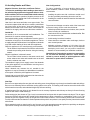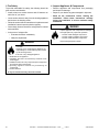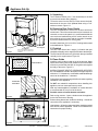
1
Installation Manual Installation and Appliance Setup INSTALLER: Leave this manual with party responsible for use and operation. Owner: Retain this manual for future reference. WARNING NOTICE: SAVE THESE INSTRUCTIONS Please read this entire manual before installation and use of this pellet fuelburning room heater. Model(s): P43, P61A & P68 Freestanding Pellet Stove Failure to follow these instructions could result in property damage, bodily injury or even death. • Do not store or use gasoline or other flammable vapors and liquids in the vicinity of this or any other appliance. • Do not overfire - If any external part starts to glow, you are overfiring. Reduce feed rate. Overfiring will void your warranty. • Comply with all minimum clearances to combustibles as specified. Failure to comply may cause house fire. WARNING HOT SURFACES! Glass and other surfaces are hot during operation AND cool down. Hot glass will cause burns. • Do not touch glass until it is cooled • NEVER allow children to touch glass • Keep children away ! CAUTION Tested and approved for wood pellets and shelled field corn fuel only. Burning of any other type of fuel voids your warranty. ! CAUTION Check building codes prior to installation. • Installation MUST comply with local, regional, state and national codes and regulations. • Contact local building or fire officials about restrictions and installation inspection requirements in your area. 1 • CAREFULLY SUPERVISE children in same room as stove. • Alert children and adults to hazards of high temperatures. High temperatures may ignite clothing or other flammable materials. • Keep clothing, furniture, draperies and other flammable materials away. NOTE To obtain a French translation of this manual, please contact your dealer or visit www.harmanstoves.com Pour obtenir une traduction française de ce manuel, s’il vous plaît contacter votre revendeur ou visitez www. harmanstoves.com Harman® • P-Series Installation Manual_R3 • 2014 -___ • 09/14 3-90-436168i ! Safety Alert Key: • DANGER! Indicates a hazardous situation which, if not avoided will result in death or serious injury. • WARNING! Indicates a hazardous situation which, if not avoided could result in death or serious injury. • CAUTION! Indicates a hazardous situation which, if not avoided, could result in minor or moderate injury. • NOTICE: Indicates practices which may cause damage to the stove or to property. TABLE OF CONTENTS Installation Standard Work Checklist. . . . . . . . . . . . . . . . . . . . . 3 1 Product Specific and Important Safety Information A. Appliance Certification. . . . . . . . . . . . . . . . . . . . . . . . . . . . . 4 B. Glass Specifications. . . . . . . . . . . . . . . . . . . . . . . . . . . . . . . C. Mobile Home Approvals. . . . . . . . . . . . . . . . . . . . . . . . . . . . D. BTU Specifications. . . . . . . . . . . . . . . . . . . . . . . . . . . . . . . . E. Non-Combustible Materials Specification. . . . . . . . . . . . . . F. Combustible Materials Specification . . . . . . . . . . . . . . . . . . G. Electrical Codes. . . . . . . . . . . . . . . . . . . . . . . . . . . . . . . . . . 4 4 5 5 5 5 2 Getting Started A. Design and Installation Considerations . . . . . . . . . . . . . . . . 6 B. Tools and Supplies Needed. . . . . . . . . . . . . . . . . . . . . . . . . 7 C. Inspect Appliance and Components. . . . . . . . . . . . . . . . . . . 7 5 Appliance Setup A. Unpacking . . . . . . . . . . . . . . . . . . . . . . . . . . . . . . . . . . . . . B. Removing Rear Cover Panels. . . . . . . . . . . . . . . . . . . . . . C. Firebrick. . . . . . . . . . . . . . . . . . . . . . . . . . . . . . . . . . . . . . . D. Flame Guide. . . . . . . . . . . . . . . . . . . . . . . . . . . . . . . . . . . . E. Room Sensor. . . . . . . . . . . . . . . . . . . . . . . . . . . . . . . . . . . F. Low Draft Voltage Adjustment . . . . . . . . . . . . . . . . . . . . . . 21 21 21 21 22 22 6 Reference Materials A. Safety Reminders. . . . . . . . . . . . . . . . . . . . . . . . . . . . . . . . 23 B. Wiring Diagram. . . . . . . . . . . . . . . . . . . . . . . . . . . . . . . . . . 24 = Contains updated information 3 Framing and Clearances A. Appliance Dimension Diagram. . . . . . . . . . . . . . . . . . . . . . . 8 B. Clearances to Combustibles . . . . . . . . . . . . . . . . . . . . . . . . 9 C. Floor Protection . . . . . . . . . . . . . . . . . . . . . . . . . . . . . . . . . 10 D. Mobile Home Installation . . . . . . . . . . . . . . . . . . . . . . . . . . 10 4 Termination Location and Vent Information A. Vent Termination Minimum Clearances. . . . . . . . . . . . . . . B. Chimney Diagram. . . . . . . . . . . . . . . . . . . . . . . . . . . . . . . C. Venting & Use of Elbows . . . . . . . . . . . . . . . . . . . . . . . . . . D. Outside Air. . . . . . . . . . . . . . . . . . . . . . . . . . . . . . . . . . . . . E. Locating Your Appliance and Chimney. . . . . . . . . . . . . . . . F. Draft. . . . . . . . . . . . . . . . . . . . . . . . . . . . . . . . . . . . . . . . . . G. Negative Pressure. . . . . . . . . . . . . . . . . . . . . . . . . . . . . . . H. Avoiding Smoke & Odors. . . . . . . . . . . . . . . . . . . . . . . . . . I. Fire Safety . . . . . . . . . . . . . . . . . . . . . . . . . . . . . . . . . . . . . J. Inspect Appliance & Components . . . . . . . . . . . . . . . . . . . 2 11 15 16 17 18 18 18 19 20 20 Harman® • P-Series Installation Manual_R3 • 2014 -___ • 09/14 3-90-436168i Installation Standard Work Checklist attention installer: Follow this Standard Work Checklist This standard work checklist is to be used by the installer in conjunction with, not instead of, the instructions contained in this installation manual. Customer: ________________________________Date Installed:__________________________ Lot/Address: ________________________________ Location of Stove: __________________________ ________________________________Installer:__________________________ Model:________________________________ Dealer/Distributer Ph #__________________________ Serial Number:__________________________ WARNING! Risk of Fire or Explosion! Failure to install appliance to these instructions can lead to a fire or explosion. ! Appliance InstallYESIF NO, WHY? Required non-combustible floor protection (Pg. 9) ________________________________ Verified clearances to combustible. (Pg. 11-14) ________________________________ Unit is Leveled and secured. ________________________________ Venting/Chimney Section 4 (Pg. 11-19) Venting Configuration complies to vent diagrams. Venting installed, sealed and secured in place with proper clearances. Exterior wall/roof flashing installed and sealed Terminations installed and sealed. ________________________________ ________________________________ ________________________________ ________________________________ Electrical Section 1 (Pg. 5) 120VAC unswitched power provided to the appliance. ________________________________ ________________________________ ________________________________ ________________________________ ________________________________ Appliance Setup Section 5 (Pg. 21-22) All packaging and protective materials are removed Accessories installed properly Manual bag and all it’s contents are removed from inside the appliance and given to party responsible for use and operation Started appliance and verified that all motors and blowers operate as they should. Hearth and Home Technologies recommends the following: Photographing the installation and copying this checklist for your file. This checklist remain visible at all times on the appliance until the installation is complete. Comments: Further description of the issues, who is responsible (Installer/Builder/Other Trades, etc.) and corrective action needed __________________________________________________________________________________________ _________________________________________________________________________________________________ _________________________________________________________________________________________________ Comments communicated to party responsible____________________ by ________________________ on __________ 3 (Builder / Gen Contractor) (Installer) Harman® • P-Series Installation Manual_R3 • 2014 -___ • 09/14 (Date) 3-90-436168i 1 Product Specific and Important Safety Information A. Appliance Certification B. Glass Specifications MODEL: P43 Pellet Stove LABORATORY: OMNI Test Laboratories, Inc REPORT NO. 135-S-23-4, 135-S-23b-6.2 TYPE: Pellet Fueled/Supplementary For Residential Use STANDARD(s): ASTM E 1509-04, ULC/ORDC1482-M1990, ULC-S627-00 MODEL: P61A Pellet Stove LABORATORY: OMNI Test Laboratories, Inc REPORT NO. 135-S-22-4, 135-S-22b-6.2 TYPE: Pellet Fueled/Supplementary For Residential Use STANDARD(s): ASTM E 1509-04, ULC/ORDC1482-M1990, ULC-S627-00 MODEL: P68 Pellet Stove LABORATORY: OMNI Test Laboratories, Inc REPORT NO. 135-S-13-2, 135-S-13b-2, 135-S-13c-6.2 TYPE: Pellet Fueled/Supplementary For Residential Use STANDARD(s): ASTM E 1509-04, ULC/ORDC1482-M1990, ULC-S627-00 This appliance is equipped with 5mm mirrored ceramic glass. Replace glass only with 5mm ceramic glass. Please contact your dealer for replacement glass. C. Mobile Home Approved This appliance is approved for mobile home installations when not installed in a sleeping room and when an outside combustion air inlet is provided. The structural integrity of the mobile home floor, ceiling, and walls must be maintained. The appliance must be properly grounded to the frame of the mobile home and use only listed pellet vent, Class “PL” connector pipe. A Harman® Outside Air Kit must be installed in a mobile home installation. ! WARNING T he S tructural I ntegrity O f T he Manufactured Home Floor, Wall, and Ceiling/Roof Must Be Maintained. Do not install in sleeping room. NOTE: This installation must conform with local codes. In the absence of local codes you must comply with the ASTM E1509-2004, ULC S628-93, ULC/ORD-C1482-M1990, (UM) 84-HUD The P61A and P68 Freestanding Pellet Stove by Harman® are exempt from Environmental Protection Agency certification under 40 CFR 60.531 by definition [Wood Heater (A) “Air to Fuel Ratio]. The P43 is EPA certified to comply with July 1990 particulate emission standards. 4 Harman® • P-Series Installation Manual_R3 • 2014 -___ • 09/14 3-90-436168i D. BTU & Efficiency Specifications P43 Freestanding Pellet Stove: Particulate Emissions Rating: Average Emissions - 1.4 g/h *BTU Output: 12,631 - 32,163 / hr Heating Capacity: up to 2,400 sq. ft. depending on climate zone Hopper Capacity: 50 lbs Fuel: Wood Pellets or Shelled Corn Shipping Weight: 212 lbs P61A Freestanding Pellet Stove: Particulate Emissions Rating: N/A *BTU Output: 0 - 61,000 / hr Heating Capacity: up to 3,500 sq. ft. depending on climate zone Hopper Capacity: 72 lbs Fuel: Wood Pellets or Shelled Corn Shipping Weight: 249 lbs E. Non-Combustible Materials Specification Material which will not ignite and burn. Such materials are those consisting entirely of steel, iron, brick, tile, concrete, slate, glass or plasters, or any combination thereof. Materials that are reported as passing ASTM E 136, Standard Test Method for Behavior of Materials in a Vertical Tube Furnace at 750° C and UL763 shall be considered non-combustible materials. F. Combustible Materials Specification Materials made of or surfaced with wood, compressed paper, plant fibers, plastics, or other material that can ignite and burn, whether flame proofed or not, or plastered or unplastered shall be considered combustible materials. G. Electrical Codes 120 VAC, 60 Hz, Start 4.2 Amps, Run 2.8 Amps NOTE: Some generator or battery back-up systems may not be compatible with the micro-processor electronics on this appliance. Please consult the power supply manufacturer for compatible systems. WARNING! Risk of Fire! Hearth & Home Technologies disclaims any responsibility for, and the warranty and agency listing will be voided by the below actions. DO NOT: P68 Freestanding Pellet Stove: • Install or operate damaged appliance • Modify appliance • Install other than as instructed by Hearth & Home Technologies Particulate Emissions Rating: N/A *BTU Output: 0 - 68,000 / hr Heating Capacity: up to 3,900 sq. ft. depending on climate zone • Operate the appliance without fully assembling all components Hopper Capacity: 76 lbs • Overfire Fuel: Wood Pellets or Shelled Corn Shipping Weight: 290 lbs • Install any component not approved by Hearth & Home Technologies • Install parts or components not Listed or approved. • Disable safety switches *BTU output will vary, depending on the brand of fuel you use in your appliance. Consult your Harman® dealer for best results. Improper installation, adjustment, alteration, service or maintenance can cause injury or property damage. For assistance or additional information, consult a qualified installer, service agency or your dealer. NOTE: Hearth & Home Technologies, manufacturer of this appliance, reserves the right to alter its products, their specifications and/or price without notice. Harman® is a registered trademark of Hearth & Home Technologies. 5 Harman® • P-Series Installation Manual_R3 • 2014 -___ • 09/14 3-90-436168i 2 Getting Started A. Design and Installation Considerations 1. Appliance Location Since pellet exhaust can contain ash, soot or sparks, you must consider the location of: Notice: Check building codes prior to installation. • Windows • Installation MUST comply with local, regional, state and national codes and regulations. • Air Intakes • Consult insurance carrier, local building inspector, fire officials or authorities having jurisdiction over restrictions, installation inspection and permits. • Overhang, soffits, porch roofs, adjacent walls It is a good idea to plan your installation on paper, using exact measurements for clearances and floor protection, before actually beginning the installation Consideration must be given to: • Safety, convenience, traffic flow • Placement of the chimney and chimney connector. • If you are not using an existing chimney, place the appliance where there will be a clear passage for a factory-built listed chimney through the ceiling and roof. • Installing an optional outside air kit would affect the location of the vent termination. • Air Conditioner • Landscaping, vegetation When locating vent and venting termination, vent above roof line when possible. Warning! Risk of Fire Damaged parts could impair safe operation. Do NOT install damaged, incomplete or substitute components. CAUTION! If burning shelled field corn, you must use approved venting specifically designed for corn to prevent corrosion or degradation. Follow the instructions from the venting manufacturer. Notice: Locating the appliance in a location of considerable air movement can cause intermittent smoke spillage from appliance. Do not locate appliance near: • Frequently open doors • Central heat outlets or returns Recommended Location: • Above peak Recommended Location: • Above peak • Inside heated space Marginal Location: • Below peak Marginal Location: • Wind loading possible Location NOT recommended: • Not the highest point of the roof • Wind loading possible Location NOT recommended: • Too close to tree • Below adjacent structure • Lower roof line • Avoid outside wall Recommended: • Insulated exterior chase in cooler climates Windward Leeward Recommended: Outside Air Intake on windward side Multi-level Roofs NOT recommended: Outside Air Intake on leeward side Figure 2.1 6 Harman® • P-Series Installation Manual_R3 • 2014 -___ • 09/14 3-90-436168i B. Tools And Supplies Needed Tools and building supplies normally required for installation, unless installing into an existing masonry fireplace: Reciprocating Saw Hammer Phillips Screwdriver Tape Measure Level Non-Combustible Sealant Material Gloves Safety Glasses Electric Drill & Bits May also need: Vent Support Straps Venting Paint C. Inspect Appliance and Components • Carefully remove the appliance and components from the packaging. • The vent system components and decorative doors and fronts may be shipped in separate packages. • Report to your dealer any parts damaged in shipment, particularly the condition of the glass. • Read all of the instructions before starting the installation. Follow these instructions carefully during the installation to ensure maximum safety and benefit. WARNING! Risk of Fire or Explosion! Damaged parts could impair safe operation. DO NOT install damaged, incomplete or substitute components. Keep appliance dry. Hearth & Home Technologies disclaims any responsibility for, and the warranty will be voided by the following actions: • Installation and use of any damaged appliance or vent system component. • Modification of the appliance or vent system. • Installation other than as instructed by Hearth & Home Technologies. • Installation and/or use of any component part not approved by Hearth & Home Technologies. Any such action may cause a fire hazard. ! WARNING Risk of Fire, Explosion or Electric Shock! DO NOT use this appliance if any part has been under water. Call a qualified service technician to inspect the appliance and to replace any part of the control system which has been under water. 7 Harman® • P-Series Installation Manual_R3 • 2014 -___ • 09/14 3-90-436168i 3 Clearances A. Appliance Dimension Diagram Dimensions are actual appliance dimensions. Use for reference only. P43 Freestanding Pellet Stove 10 " 13 3/4” 10" 13 3/4" 5 1/8" 36 1/2" Outside Air Intake 33 1/2" Outside Air Intake P61A Freestanding Pellet Stove 5 1/8" 22" 29 3/8" 28 5/16" 23 1/2" 20 3/4" P68 Freestanding Pellet Stove 10 " 13 3/4” 37 1/2” Outside Air Intake 5 1/4" 29 3/8" 23-1/2” Figure 3.1 8 Harman® • P-Series Installation Manual_R3 • 2014 -___ • 09/14 3-90-436168i B. Clearances to Combustibles When selecting a location for the appliance it is important to consider the required clearances to walls (see Figure 3.2). ! WARNING Risk of Fire or Burns! Provide adequate clearance around air openings and for service access. Due to high temperatures, the appliance should be located out of traffic and away from furniture and draperies. NOTICE: Illustrations reflect typical installations and are FOR DESIGN PURPOSES ONLY. Actual installation may vary due to individual design preference. ! CAUTION This appliance must be vented to the outside. Due to high temperatures, the stove should be placed out of traffic and away from furniture and draperies. Children and adults should be alerted to the hazards of high surface temperatures and should stay away to avoid burns to skin and/or clothing. Young children should be carefully supervised when they are in the same room as the stove. Clothing and other flammable materials should not be placed on or near this unit. Place the stove away from combustible walls at least as far as shown in Figure 3.2. Please note the difference in side wall clearance with and without side shields. Note that the clearances shown are minimum for safety but do not leave much room for access when cleaning or servicing. Please take this into account when placing the stove. Alternate floor protector dimension may be used as long as they satisfy the measurement requirements shown below. Minimum size floor protection for a corner installation hearth pad is 36" x 36". P61A & P68 Freestanding Pellet Stove P43 Freestanding Pellet Stove 2"(51mm) 14" (355mm) with side shields 20" (508mm) without side shields 14" (355mm) 20" (508mm) *16" (406mm) without side shields 9"(228mm) 9"(228mm)13"(330mm) 9"(228mm) 9"(228mm)13"(330mm) 13"(330mm) Without Side Shields *10" (254mm) *16" (406mm) 36"(914mm) 36"(914mm) 9"(228mm)With Side Shields 2"(51mm) *10" (254mm) with side shields 9" (228mm) With or Without Side Shields Figure 3.2 9 Harman® • P-Series Installation Manual_R3 • 2014 -___ • 09/14 3-90-436168i C. Floor Protection Place the stove on a noncombustible type floor or floor protector that extends a minimum of 6 inches (152mm) to the front of the load door opening, 6 inches (152mm) to the sides of the door opening, and 6 inches to the rear. Floor protection must also extend 2 inches (51mm) beyond each side of any horizontal flue pipe. The minimum floor protector material is 20 gauge sheet metal. Other floor protector materials are ceramic tile, stone, brick, etc. Figure 3.3 NOTE for Canadian installation only: Per ULC-S627-00, If installed on a combustible floor, the need to provide a noncombustible floor protector covering the area beneath the space heater and extending at least 17.72” (450mm) on the firing side and at least 7.87” (200mm) on the other sides. D. Mobile Home Installation When installing this unit in a mobile home, several requirements must be followed: 1. The unit must be bolted to the floor. This can be done with 1/4” lag screws through the 2 holes in the base plate. 2. The unit must also be connected to outside air. See section 4-D Outside Air. 3. Floor protection and clearances must be followed as shown. 4. Unit must be grounded to the metal frame of the mobile home. In Canada, you may follow smaller U.S. floor protection requirements ONLY if the user agrees to completely shut-down the appliance, and allow it to cool to where all fire is extinguished and the combustion blower and its indicator light shuts off, prior to opening the firebox door or ash door. P43 - Minimum size rectangular floor protection (USA) is 321/2" wide By 33" deep (825mm X 838mm). P61A - Minimum size rectangular floor protection (USA) is 285/16” Deep By 243/4” Wide (719mm X 629mm). P68 - Minimum size rectangular floor protection (USA) is 33” Deep By 25” Wide (838mm X 635mm). *Floor protection dimensions for the front and sides are measured from the appliance door opening in The United States. In Canada, the side dimension is measured from the widest part of the appliance. Floor Protection Requirements US J Sides 6" 200mm K Front 6" 450mm L Rear 6" 200mm Corner to edge dimension for corner installation floor protection. Canada P43 = 42-5/8” P61A/P68 = 50” NOTE: Measurement "L" is measured from the pedestal base in the US ONLY NOTE: Measurement “K” is measured from the glass in the US ONLY L J Canada J USA K Floor protector Figure 3.3 10 Harman® • P-Series Installation Manual_R3 • 2014 -___ • 09/14 3-90-436168i 4 Termination Location and Vent Information A. Vent Termination Minimum Clearances #1 Preferred method (Figure 4.1) This method provides excellent venting for normal operation and allows the stove to be installed closest to the wall. Two inches from the wall is safe; however, four inches allows better access to remove the rear panel. The vertical portion of the vent should be three to five feet high. This vertical section will help provide natural draft in the event of a power failure. Seal pipe joints with silicone or aluminum tape in addition to the sealing system used by the manufacturer. Note: Do not place joints within wall pass-through. 3 Ft. to Combustibles 3 Ft. to Combustibles Figure 4.1 #2 Preferred method (Figure 4.2) This method also provides excellent venting for normal operation but requires the stove to be installed farther from the wall. The vertical portion of the vent should be three to five feet high and at least 1” from a combustible wall. This vertical section will provide natural draft in the event of a power failure. Seal pipe joints with silicone or aluminum tape in addition to the sealing system used by the manufacturer. 3 Ft. to Combustibles If the stove is installed below grade be sure the vent termination is at least 12" above grade (with outside air only). The outlet must also be 1 foot from the house/building. Note: Do not place joints within wall pass-through. ! CAUTION Keep combustible materials (such as grass, leaves, etc.) at least 3 feet away from the flue outlet on the outside of the building. 3 Ft. to Combustibles Figure 4.2 11 Harman® • P-Series Installation Manual_R3 • 2014 -___ • 09/14 3-90-436168i #3 Installing into an existing chimney (Figure 4.3) This method provides excellent venting for normal operation. This method also provides natural draft in the event of a power failure. If the chimney condition is questionable* you may want to install a liner as in method #7. In some places in the US and Canada it is required that the vent pipe extend all the way to the top of the chimney. *The chimney should be inspected and cleaned before installing your stove. If you discover that the chimney does not have a clay tile liner or has cracks or flaking of the tile liner you will need to install a stainless steel liner within the chimney. In most cases the inside diameter of this liner should be 4". Either flexible or rigid liner may be used for this purpose. Refer to Method 6 & 7. Seal pipe joints with silicone or aluminum tape in addition to the sealing system used by the manufacturer. Be sure to design the venting so that it can be easily cleaned. Figure 4.3 #4 Installing into an existing fireplace chimney (Figure 4.4) This method provides excellent venting for normal operation. This method also provides natural draft in the event of a power failure. If the chimney condition is questionable* you may want to install a liner as in method #6. In some places in the US and Canada it is required that the vent pipe extend all the way to the top of the chimney. *The chimney should be inspected and cleaned before installing your stove. If you discover that the chimney does not have a clay tile liner or has cracks or flaking of the tile liner you will need to install a stainless steel liner within the chimney. In most cases the inside diameter of this liner should be 4". Either flexible or rigid liner may be used for this purpose. Refer to Method 5 & 6. The chimney should be sealed at the damper using a steel plate. Kaowool, mineral wool or an equivalent noncombustible insulation is recommended to be installed on top of the sealing plate to reduce the possibility of condensation. The connector pipe should extend through the smoke chamber to the base or into the first flue tile. Seal pipe joints with silicone or aluminum tape in addition to the sealing system used by the manufacturer. Be sure to design the venting so that it can be easily cleaned. Figure 4.4 12 Harman® • P-Series Installation Manual_R3 • 2014 -___ • 09/14 3-90-436168i #5 Installing into an existing fireplace chimney (Figure 4.5) w/Full Liner This method provides excellent venting for normal operation. This method also provides natural draft in the event of a power failure. In some places in the US and Canada it is required that the vent pipe extend all the way to the top of the chimney. The pipe or liner inside the chimney should be 4" diameter. In this method a cap should also be installed on the chimney to keep out rain. Be sure to use approved pellet vent pipe fittings. Seal pipe joints with silicone or aluminum tape in addition to the sealing system used by the manufacturer. Pipe size should be increased to 4" using this method. Figure 4.5 #6 Installing into an existing chimney (Figure 4.6) w/Full liner This method provides excellent venting for normal operation. This method also provides natural draft in the event of a power failure. In some places in the US and Canada it is required that the vent pipe extend all the way to the top of the chimney. Seal pipe joints with silicone or aluminum tape in addition to the sealing system used by the manufacturer. The pipe or liner inside the chimney should be 4" diameter. In this method a cap should also be installed on the chimney to keep out rain. Figure 4.6 13 Harman® • P-Series Installation Manual_R3 • 2014 -___ • 09/14 3-90-436168i IN 12" M storm collar flashing 1" MIN. 1" MIN. 1" MIN. No insulation or other combustible materials are allowed within 3" of the PL vent pipe. PL vent manufacturer's firestop spacer and support Minimum flue vent configuration It is recommended that outside air be installed with this venting configuration. 12" min. above ground level 1” MIN. Figure 4.7 Figure 4.8 #7 Installing through the ceiling Through the ceiling vent, follow PL vent manufacturers recommendations when using wall and ceiling pass through. Area within dotted circle represents the minimum clearance to combustible materials such as shrubbery, mulch or tall grasses. Seal pipe joints with silicone or aluminum tape in addition to the sealing system used by the manufacturer. Note: Do not place joints within wall pass-through. min. wall to outlet 12" mi n co . cle mb ara 36 us nc " tib e t le o a ma ny ter ial Figure 4.9 14 Harman® • P-Series Installation Manual_R3 • 2014 -___ • 09/14 3-90-436168i B. Chimney Diagram Inside Corner Detail Do or Fixed Closed Openable Porch or Deck Openable or Fixed Fixed Closed Openable Sidewalk V =Vent Terminal A =Air Supply Inlet =Area where termination is not permitted Figure 4.10 Requirements for Terminating the Venting WARNING: Venting terminals must not be recessed into a wall or siding. NOTE: Only PL vent pipe wall pass-through and fire stops should be used when venting through combustible materials. NOTE: Always take into consideration the effect the prevailing wind direction or other wind currents will cause with flyash and /or smoke when placing the termination. In addition, the following must be observed: A. The clearance above grade must be a minimum of 12". B. The clearance to a window or door that may be opened must be a minimum of 48" to the side and 48" below the window/door, and 12" above the window/door. (with outside air installed, 12” to side and below) C. A 12" clearance to a permanently closed window is recommended to prevent condensation on the window. D. The vertical clearance to a ventilated soffit located above the terminal within a horizontal distance of 2 feet (60 cm) from the center-line of the terminal must be a minimum of 18". E. The clearance to an unventilated soffit must be a minimum of 12". F. The clearance to an outside corner is 11" from center of pipe. G. The clearance to an inside corner is 12". H. A vent must not be installed within 3 feet (90 cm) above a gas meter/regulator assembly when measured from the horizontal center-line of the regulator. 15 I. The clearance to service regulator vent outlet must be a minimum of 6 feet. J. The clearance to a non-mechanical air supply inlet to the building or the combustion air inlet to any other appliance must be a minimum of 48”. K. The clearance to a mechanical air supply inlet must be a minimum of 10 feet. (with outside air installed, 6 feet) L. The clearance above a paved sidewalk or a paved driveway located on public property must be a minimum of 7 feet. M. The clearance under a veranda, porch, deck or balcony must be a minimum of 12 inches. (B. also) NOTE: The clearance to vegetation and other exterior combustibles such as mulch is 36” as measured from the center of the outlet or cap. This 36” radius continues to grade or a minimum of 7 feet below the outlet. Certain Canadian and or Local codes or regulations may require different clearances. A vent shall not terminate directly above a side-walk or paved driveway which is located between two single family dwellings and serves both dwellings. Only permitted if veranda, porch, deck, or balcony is fully open on a minimum of 2 sides beneath the floor. See NFPA 211 for more installation clearance reductions when using outside air. NOTE: Where passage through a wall, or partition of combustible construction is desired, the installation shall conform to CAN/CSA-B365. (if in Canada) Harman® • P-Series Installation Manual_R3 • 2014 -___ • 09/14 3-90-436168i C. Venting & Use of Elbows Use only the specified venting components. Use of any other components will void the product warranty and may pose a hazard. + + + = Positive static pressure O - = Negative static pressure O Figure 4.11 A combustion blower is used to extract the combustion gases from the firebox. This causes a negative pressure in the firebox and a positive pressure in the venting system as shown in Figure 4.11. The longer the vent pipe and more elbows used in the system, the greater the flow resistance. The recommended maximum flue lengths for the P-Series Pellet Stove are as follows: 4" Stainless Steel Flex: 30 Lineal ft. Vertical* Do Not Install A Flue Damper In The Exhaust Venting System Of This Appliance. DO NOT CONNECT THIS UNIT TO A CHIMNEY FLUE SERVING ANOTHER APPLIANCE. NOTE: Simpson DuraVent PelletVent Pro Harman ® Adapter Part #3PVP-ADHB and PelletVent Pro Harman® Adapter Increaser Part #3PVP-X4ADHB are highly recommended to be installed on the starter collar to insure a proper pipe connection to the unit. INSTALL VENT AT CLEARANCES SPECIFIED BY THE VENT MANUFACTURER Use silicone to create an effective vapor barrier at the location where the chimney or outside air ducting passes through to the exterior of the structure. 4" PL Vent Pipe: 4" Pl Vent Pipe: 30 Lineal ft. Vertical* 4" Pl Vent Pipe: 14 ft. Vertical w/1-90° and 4 lineal ft. horizontal* If additional 4" PL Vent fittings are required, the overall length must be reduced by: Vertical 90° or T: 2.5' Vertical 45°: 1.5' Horizontal 90° or T: 5.0' Horizontal 45°: 2.5' 3" PL Vent Pipe: 20 Lineal ft. vertical* 8 Lineal ft. vertical w/1-90° & 4 lineal ft. horizontal* If additional 3" PL Vent fittings are required, the overall length must be reduced by: Vertical 90° or T: 2.0' Vertical 45°: 1.0' Horizontal 90° or T: 4.0' Horizontal 45°: 2.0' * Long runs of flex or PL vent pipe installed directly vertical from the flue stub may require more frequent cleaning due to fly ash falling off inside and collecting directly above the combustion blower outlet. Any use of horizontal venting will require more frequent cleaning. It is the responsibility of the installer to make sure the entire flue configuration is accessible for cleaning. 4" stainless steel flex vent piping is only allowed for use in masonry fireplaces and chimneys or factory built wood burning fireplaces with class A metal chimneys. All pellet vent pipe must be secured together either by means provided by pipe manufacturer or by 3 screws at each joint. 16 Harman® • P-Series Installation Manual_R3 • 2014 -___ • 09/14 3-90-436168i D. Outside Air Outside Air: Hearth & Home Technologies recommend attaching outside air in all installations, especially lower level and main floor locations. Outside air flex pipe goes here. Per national building codes, consideration must be given to combustion air supply to all combustion appliances. Failure to supply adequate combustion air for all appliance demands, may lead to back-drafting of those and other appliances. When the appliance is side-wall vented: The air intake is best located on the same exterior wall as the exhaust vent outlet and located lower on the wall than the exhaust vent outlet. When the appliance is roof vented: The air intake is best located on the exterior wall oriented towards the prevailing wind direction during the heating season. Figure 4.12 Termination Cap part# 1-10-09542 Figure 4.13 Direct Vent Wall Pass-through Kit (Part #1-00-677177) The outside air connection will supply the demands of the pellet appliance, but consideration must be given to the total house demand. House demand may consume some air needed for the stove, especially during a power failure. It may be necessary to add additional ventilation to the space in which the pellet appliance is located. Consult with your local HVAC professional to determine the ventilation demands for your house. To install outside air use 3". non-combustible flex pipe Figure 4.13. There is a break-away hole on the rear panel of the P-Series stove which must be removed before connecting the flex pipe. Figure 4.12. The pipe should be run outside and terminate to the side or below the vent pipe outlet so the flue outlet is more than 12" from the inlet cover. The Termination Cap should be used to keep birds, rodents, etc. out of the pipe Figure 4.13. You may choose to use the optional Direct Vent Wall Passthrough Kit which incorporates the venting pass-through and outside air inlet into one component. Figure 4.14. Figure 4.14 17 Harman® • P-Series Installation Manual_R3 • 2014 -___ • 09/14 3-90-436168i E.Locating Your Appliance & Chimney G.Negative Pressure Location of the appliance and chimney will affect performance. ! • Install through the warm airspace enclosed by the building envelope. This helps to produce more draft, especially during lighting and die-down of the fire. • Penetrate the highest part of the roof. This minimizes the effects of wind loading. • Locate termination cap away from trees, adjacent structures, uneven roof lines and other obstructions. • Minimize the use of chimney offsets. • Consider the appliance location relative to floor and ceiling and attic joists. ! CAUTION • DO NOT CONNECT TO ANY AIR DISTRIBUTION DUCT OR SYSTEM. May allow flue gases to enter the house F.Draft Draft is the pressure difference needed to vent appliances successfully. When an appliance is drafting successfully, all combustion by products are exiting the home through the chimney. Considerations for successful draft include: • Preventing negative pressure • Location of appliance and chimney To measure the draft or negative pressure on your appliance use a magnahelic or a digital pressure gauge capable of reading 0 - 1 inches of water column (W.C.). The appliance should be running on high for at least 15 minutes for the test. With the stove running on high you should have a negative pressure equal to or greater than the number given in the chart below. If you have a lower reading than you find on the chart, your appliance does not have adequate draft to burn the fuel properly. .35 - .55 Prior to installing the flue pipe, connect a draft meter. (The draft meter must have a minimum range of 0 - .5”) Record the first reading. Connect flue pipe to stove and be sure all doors and windows in the home are closed. Record the second draft reading _______. If the second reading is more than .05” lower than the first reading, check for possible restrictions or the need for outside air. For more information on the draft test procedure, refer to Page 21 18 Risk of Asphyxiation! Negative pressure can cause spillage of combustion fumes and soot. Negative pressure results from the imbalance of air available for the appliance to operate properly. It can be strongest in lower levels of the house. Causes include: • Exhaust fans (kitchen, bath, etc.) • Range hoods • Combustion air requirements for furnaces, water heaters and other combustion appliances • DO NOT CONNECT THIS UNIT TO A CHIMNEY FLUE SERVICING ANOTHER APPLIANCE. Minimum Vacuum Requirements: WARNING • Clothes dryers • Location of return-air vents to furnace or air conditioning • Imbalances of the HVAC air handling system • Upper level air leaks such as: - Recessed lighting - Attic hatch - Duct leaks To minimize the effects of negative air pressure: • Install the outside air kit with the intake facing prevailing winds during the heating season • Ensure adequate outdoor air for all combustion appliances and exhaust equipment • Ensure furnace and air conditioning return vents are not located in the immediate vicinity of the appliance • Avoid installing the appliance near doors, walkways or small isolated spaces • Recessed lighting should be a “sealed can” design • Attic hatches weather stripped or sealed • Attic mounted duct work and air handler joints and seams taped or sealed Notice: Hearth & Home Technologies assumes no responsibility for the improper performance of the chimney system caused by: • Inadequate draft due to environmental conditions • Downdrafts • Tight sealing construction of the structure • Mechanical exhausting devices Harman® • P-Series Installation Manual_R3 • 2014 -___ • 09/14 3-90-436168i H.Avoiding Smoke and Odors Vent Configurations: Negative Pressure, Shut-down, and Power Failure: To reduce probability of reverse drafting during shutdown conditions, Hearth & Home Technologies strongly recommends: To reduce the probability of back-drafting or burn-back in the pellet burning appliance during power failure or shutdown conditions, the stove must be able to draft naturally without exhaust blower operation. Negative pressure in the house will resist this natural draft if not accounted for in the pellet appliance installation. Heat rises in the house and leaks out at upper levels. This air must be replaced with cold air from outdoors, which flows into lower levels of the house. Vents and chimneys into basements and lower levels of the house can become the conduit for air supply, and reverse under these conditions. Outside Air An outside air kit is recommended in all installations. The Outside Air Kit must be ordered separately. Per national building codes, consideration must be given to combustion air supply to all combustion appliances. Failure to supply adequate combustion air for all appliance demands may lead to back drafting of those and other appliances. When the appliance is roof vented (strongly recommended): The air intake is best located on the exterior wall oriented towards the prevailing wind direction during the heating season. When the appliance is side-wall vented: The air intake is best located on the same exterior wall as the exhaust vent outlet and located lower on the wall than the exhaust vent outlet. • Installing the pellet vent with a minimum vertical run of five feet, preferably terminating above the roof line. • Installing the outside air intake at least four feet below the vent termination. To prevent soot damage to exterior walls of the house and to prevent re-entry of soot or ash into the house: • Maintain specified clearances to windows, doors, and air inlets, including air conditioners. • Vents should not be placed below ventilated soffits. Run the vent above the roof. • Avoid venting into alcove locations. • Vents should not terminate under overhangs, decks or onto covered porches. • Maintain minimum clearance of 12 inches from the vent termination to the exterior wall. If you see deposits developing on the wall, you may need to extend this distance to accommodate your installation conditions. Hearth & Home Technologies assumes no responsibility for, nor does the warranty extend to, smoke damage caused by reverse drafting of pellet appliances under shut-down or power failure conditions. The outside air supply kit can supply most of the demands of the pellet appliance, but consideration must be given to the total house demand. House demand may consume the air needed for the appliance. It may be necessary to add additional ventilation to the space in which the pellet appliance is located. Consult with your local HVAC professional to determine the ventilation demands for your house. Vent Pipe Be sure to use approved pellet vent pipe wall and ceiling pass- through fittings to go through combustible walls and ceilings. Be sure to use a starting collar to attach the venting system to the stove. The starting collar must be secured to the flue stub with at least three screws, and sealed with high temp silicone caulking. 4" stainless steel flex vent piping is only allowed for use in masonry fireplaces and chimneys or factory built wood burning fireplaces with class A metal chimneys. Pellet venting pipe (also known as Type L vent) is constructed of two layers with air space between the layers. This air space acts as an insulator and reduces the outside surface temperature to allow a clearance to combustibles of only 1 inch. The sections of pipe lock together to form an air tight seal in most cases; however, in some cases a perfect seal is not achieved. For this reason and the fact that the P-Series operates with a positive vent pressure, we specify that the joints also be sealed with silicone. Where passing through an exterior wall or roof, be sure to use the appropriate pass-through device providing an adequate vapor barrier. Venting manufacturers generally provide these pass-through devices. 19 Harman® • P-Series Installation Manual_R3 • 2014 -___ • 09/14 3-90-436168i I. Fire Safety J. Inspect Appliance & Components • Install at least one smoke detector and CO detector on each floor of your home. • Report to your dealer any parts damaged in shipment. To provide reasonable fire safety, the following should be given serious consideration: • Locate smoke detector away from the heating appliance and close to the sleeping areas. • Follow the smoke detector manufacturer’s placement and installation instructions and maintain regularly. • Conveniently locate a Class A fire extinguisher to contend with small fires. • In the event of a hopper fire: • Evacuate the house immediately. • Notify fire department. ! WARNING • Remove appliance and components from packaging and inspect for damage. • Read all the instructions before starting the installation. Follow these instructions carefully during the installation to ensure maximum safety and benefit. ! WARNING Inspect appliance and components for damage. Damaged parts may impair safe operation. • Do NOT install damaged components. • Do NOT install incomplete components. • Do NOT install substitute components. Report damaged parts to dealer. Fire Risk. Hearth & Home Technologies disclaims any responsibility for, and the warranty will be voided by the following actions: • Installation and use of any damaged appliance. • Modification of the appliance. • Installation other than as instructed by Hearth & Home Technologies. • Installation and/or use of any component part not approved by Hearth & Home Technologies. • Operating appliance without fully assembling all components. • Do NOT Overfire. Or any such action that may cause a fire hazard. 20 Harman® • P-Series Installation Manual_R3 • 2014 -___ • 09/14 3-90-436168i 5 Appliance Set-Up A. Unpacking The P-Series is bolted (1/4 x 1" hex head bolts) to the skid to prevent movement during shipping. To free the stove from the skid you must remove the holddown bolts in the rear of the pedestal base using a 7/16” socket or wrench. Figure 5.1. B. Removing Rear Cover Panels Rear Cover Panel Rear Cover Panel The rear cover panels are secured to the stove with three screws each. Two of the screws need only be loosened, not removed, to remove the panels. It is recommended that the rear covers are installed using a 5/16” socket, wrench or nut driver after the unit is in place and the vent pipe is installed, to prevent contact with hot or moving parts. If needed, install the (2) 5/16-18 X 3/4” leveling bolts located in the hardware kit. Figure 5.1. Leveling Bolt Figure 5.1 Shipping Bolts Note: These same holes are used for securing the stove in mobile home installation. Leveling Bolt C. Firebrick The P43 Pellet Stove has a single (1) firebrick that gets installed horizontally on the angle bracket above the burnpot. The P61A and P68 have three (3) firebrick that get installed vertically on the angle bracket. Figure 5.2. D. Flame Guide 1 Firebrick P43 Pellet Stove Install the cast iron flame guide on top of the burn pot. Make sure that the flame guide is fully seated on the vertical sides of the burn pot and that the back of the guide rests against the body of the stove. Figure 5.3. INSTALL EXHAUST VENT AT CLEARANCES SPECIFIED BY THE MANUFACTURER. Most pellet vent pipe requires a minimum of 1" of clearance to combustible materials although some can be installed at 1" clearance. P61A & P68 Pellet Stove 3 Firebrick Follow these instructions along with all local codes regarding installation of this appliance. Do NOT use makeshift compromises when installing this appliance, serious consequences may result. With any hearth appliance, installation of smoke detectors is recommended on every level of the home. Possible causes of smoke detector activation: Paint curing process - Open a window near the appliance for the first few hours of burning. Figure 5.2 Flame guide Exhaust being drawn back inside the dwelling - Outside air connection to the appliance is necessary. Vent leakage - All interior seams and joints should be sealed with silicone where applicable. Follow vent manufacturers instructions for proper sealing. Figure 5.3 21 Harman® • P-Series Installation Manual_R3 • 2014 -___ • 09/14 3-90-436168i E. Room Sensor Installation The room sensor is a small temperature sensor on the end of a 60" wire. This sensor is installed much like a standard wall thermostat. There is a remote room sensor port on the rear of the unit for easy external connection. Use standard 18-2 thermostat wire to extend the sensor to the desired location (50' maximum). The room sensor should be installed in the location where you want to control the temperature. NOTE: Distances of more than 25 feet from the unit or in another room are not recommended. The room sensor is essential for the P-Series excellent efficiency. NOTE: It is recommended that the room sensor be installed, even if only installed on the rear of the unit as a return air sensor. F. Low Draft Voltage Adjustment These units are pre-tested at the factory with exactly 120 VAC, 60 Hz. They are checked and adjusted for firebox tightness, gasket leakage, motor operation and igniter operation. The P-Series is then factory set at a mid-point adjustment and in most cases will not need any adjustments. NOTE: The factory low draft setting may not be correct for the unit's permanent installation conditions. The control board on the P-Series is equipped with a low draft adjustment port located on the control face just to the right of the igniter light. Figure 5.4. This voltage adjustment is provided to allow the unit to be adjusted for the household voltage where the unit is going to be in permanent operation. NOTE: The line voltage varies from area to area and often home to home. If the unit is not adjusted properly, it does not cause a safety concern. If the unit is adjusted too high, only efficiency is lost. If the unit is adjusted too low, the low draft pressure switch will not allow the feed motor or the igniter to operate. A simple draft test should be performed after completing the flue pipe installation. To record the results for future reference: 1. Plug unit into a 120 VAC, 60 HZ outlet. 2. Close the hopper lid, front view door, and the ash pan door. Neither pellets or a fire are required for this test. 3. With the mode selector in the “OFF” position, turn the feed adjuster to “TEST”. 4. Record the high draft_____in W.C. (Normal is -.50 to -.60) The control will be on the High Draft for a total of 2 minutes. 5. After 1 minute, the combustion motor will go down to low draft and the distribution blower will go on high. Allow approximately 15 seconds to pass for the combustion motor to slow before checking the low draft. 6. If the low draft is between -.35 and -.45, record the reading _____ in W.C. If the reading is higher, slowly turn the set screw counter-clockwise until the draft lowers. If the reading is lower, very slowly turn the set screw clockwise until the draft increases. NOTE: In some cases, the draft may not go as low as -.35 to -.45 even with the set screw completely counterclockwise. Ideally, you should just set it as low as possible. The low draft voltage should be adjusted to achieve the most efficient burn on low burn or "maintenance". This voltage adjustment allows the installer to change the low voltage set point approximately 10 volts. This adjustment should be done by the installer during set up because a draft meter reading is required to insure proper set up. Combustion Motor Speed Control Low draft only set point. The small straight screwdriver slot is plastic; therefore, the unit can be adjusted while in operation. Draft Meter bolt hole location On a P-Series the draft test hole is under the left rear corner of the firebox on the pedestal base. Figure 5.5 Connect the power cord to a 100 VAC, 50 Hz grounded receptacle. (A surge protector is recommended to protect the circuit board.) Also be sure that the polarity of the outlet that the stove is plugged into is correct. Figure 5.4 22 Harman® • P-Series Installation Manual_R3 • 2014 -___ • 09/14 3-90-436168i 6 Reference Material A. Safety Reminders When installing and operating your Harman® P-Series, respect basic safety standards. Read these instructions carefully before you attempt to install or operate the P-Series. Failure to do so may result in damage to property or personal injury and may void the product warranty. Consult with your local building code agency and insurance representative before you begin your installation to ensure compliance with local codes, including the need for permits and follow-up inspections. ! CAUTION This appliance must be vented to the outside. Due to high temperatures, this stove should be placed out of traffic and away from furniture and draperies. Children and adults should be alerted to the hazards of high surface temperatures and should stay away to avoid burn to skin and/or clothing. Young children should be carefully supervised when they are in the same room as the stove. Clothing and other flammable materials should not be placed on or near this stove. Installation and repair of this stove should be done by a qualified service person. The appliance should be inspected before use and at least annually by a qualified service person. More frequent cleaning may be required. It is imperative that control compartments, burners, and circulating air passageways of this stove be kept clean. ! WARNING Mobile/manufactured home guidelines do not allow installation in a sleeping room. ! CAUTION THE STRUCTURAL INTEGRITY OF THE MOBILE HOME FLOOR, WALL, AND CEILING/ROOF MUST BE MAINTAINED. ! CAUTION The stove is hot while in operation. Keep children, clothing and furniture away. Contact may cause skin burns. ! WARNING Keep combustible materials such as grass, leaves, etc. At least 3 feet away from the point directly under the vent termination. ! WARNING Use of improper fuels, fire starters or altering the stove for higher heat output may cause damage to the stove and could result in a House fire. Use only approved fuels and operation guidelines 23 Harman® • P-Series Installation Manual_R3 • 2014 -___ • 09/14 3-90-436168i R COR D GREEN Harman® • P-Series Installation Manual_R3 • 2014 -___ • 09/14 DISTRIBUTION BLOWER BLUE WHITE COMBUSTION MOTOR FEEDER AUGER MOTOR N.O. CONTACTS LOW PRESSURE SWITCH WHITE BROWN WHITE ESP ESP CONTROL BOARD IGNITER ELEMENT INSIDE BURNPOT MALE/FEMALE CONNECTIONS LT.BLUE REMOTE SENSOR PORTS MAX WATTS - 516 @ 100/120VAC 50/60Hz = 4.3 A STANDARD USE WATTS - 384 @ 100/120VAC 50/60Hz = 3.2 A MALE/FEMALE CONNECTIONS BONDED TO STOVE BODY GREEN WIRE IS GROUND POWE CORD BLACK HARMAN P43/ P61A/ P68 PELLET STOVE WIRING DIAGRAM GREEN MALE/FEMALE CONNECTIONS WHITE RED UBBER YELLOW 24 LT.BLUE 18/3 R 1 5 6 7 8 WHITE WHITE EMPTY YELLOW 11 PART NO. 3-89-06504J BLACK 10 4 WHITE 9 3 WHITE RED 2 PLUGGED BLUE 1 ESP PROBE BROWN TWISTED WIRE 11 8 9 10 3 4 5 6 6 AMP GLASS FUSE B. Wiring Diagram 3-90-436168i WHITE 11 PIN PLUG 18/3 RUBBER CORD 25 Harman® • P-Series Installation Manual_R3 • 2014 -___ • 09/14 3-90-436168i Harman®, a brand of Hearth & Home Technologies Inc. 352 Mountain House Road, Halifax, PA 17032 www.harmanstoves.com Please contact your Harman® dealer with any questions or concerns. For the location of your nearest Harman® dealer, please visit www.harmanstoves.com. Printed in U.S.A. - Copyright 2012 26 Harman® • P-Series Installation Manual_R3 • 2014 -___ • 09/14 3-90-436168i