1
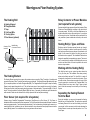
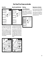
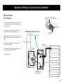
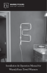
Installation Manual for your TempZone™ Electric Radiant Floor Heating System (Twin Conductor) Free Design Service • 24/7 Installation Support • No Nonsense™ Warranty • (800) 875-5285 • www.WarmlyYours.com 1 Understanding The System How The System Works You can feel the heat of a campfire even though you are not directly above it. Radiant energy transfer is caused by a warm surface (the campfire) giving up its heat to a cooler surface (your body). This radiant energy travels through space without heating the space itself. It only turns into heat when it contacts a cooler surface. By transferring this heat to all of the objects in the room, the heat slowly moves to warm the air which starts to rise. Proper Heat Dissipation All radiant heating systems rely on a “Heat Bank”. The heat moves from the source (Heating Element) into the Heat Bank (thin-set) and spreads out and warms the floor without creating an excessively hot spot. In the WarmlyYours Floor Heating System the thin-set and/or self-levelling cement acts as the Heat Bank. It is important to follow the installation guidelines to create a proper Heat Bank. Insulation – Proper Heat Retention When WarmlyYours floor heating systems are installed on a concrete slab, we strongly recommend adding a layer of insulation to the slab prior to installing the radiant floor heating system. While WarmlyYours systems provide up to 25% more heating power per square foot than the nearest competitor, the slab will always act as a “heat sink.” Some of the heat that would otherwise be transferred to the flooring surface will remain in the slab, causing the floor’s surface temperature to be considerably lower. This is true with any floor heating system. When installed on top of a concrete slab without insulation, it is generally accepted that a radiant floor heating system will take the chill away from the floor and provide a small amount of warmth. Adding insulation on top of the slab and beneath any floor heating system will allow a greater percentage of the heat generated to transfer to the flooring surface. 1 This leads to greater efficiency and therefore faster warm up times, higher expected surface temperatures and lower energy usage. The floor will have the capacity to warm to a comfortable temperature, and in some cases can be employed as the primary heat source for that room. Securing The Roll(s) Once the roll(s) is fitted into the space, it needs to be secured to the subfloor to prevent movement during the installation of the floor covering. The options for securing the roll(s) are discussed in detail on Page 5. Regardless of the method you choose, it is vital that the integrity of the Heating Element be maintained. Staples should never cross, pierce or nick the Heating Element. Minimum 2 in. spacing between adjacent heating devices. Protecting The Heating Element It is vital that proper care be taken to insure that the Heating Element is not damaged during the installation of the system or by the floor covering. A thorough preparation and detailed inspection of the subfloor will assure that any and all objects that may damage the Heating Element are removed prior to installation. Heavy gauge cardboard or carpet scraps should be used to protect the system from traffic during the flooring installation. Never Cut The Heating Element The key to the system is the uninterrupted flow of electricity through the Heating Element. Control Device Options Option 1: Programmable Thermostat The SmartStat has an in-floor sensor and a digital display that indicates the exact floor temperature. It also features a manual set-back to a “high” and a “low” temperature level, and a built-in GFCI. The programmable function allows you 4 setting changes for each day of the week. Its maximum capacity is 1800 watts at 120 VAC or 3600 watts at 240 VAC . Any floor requiring more power will need to be zoned with more than one SmartStat™ and a Relay Contactor or with a Master Thermostat and Power Modules. Option 2: EasyStat Non-Programmable Thermostat The EasyStat™ has an in floor sensor just like the SmartStat™, but requires no programming. Just enter the floor temperature using either Fahrenheit or Celcius. It is equipped with a GFCI and is available in 15 amps at both 120 volt and 240 voltages. A floor requiring more power will need to be zoned with more than one SmartStat and a Relay Contactor or with a Master Thermostat and Power Modules. We recommend an inside wall, away from sunshine. Items Needed For The System Installation System Components From WarmlyYours Ground Fault Circuit Interrupter 1. The Customized Installation Plan (or layout). GFCI or ‘GFCI-breaker’ indicating its capacity if not incorporated into the control device you are using. This is a built-in feature of the SmartStat Programmable Thermostat, EasyStat or Comfort Regulator. 2. Heating Roll(s) (15-watt/ sq. ft.) If multiple rolls are connected to the same control device, they must be of the same voltage type and wired in parallel. 3. Control Device (one of the following): • SmartStat™ Programmable Thermostat • EasyStat™ Non-Programmable Thermostat • Comfort Regulator 4. You may also have a relay contactor or power module, if your system is being installed in a large area. IMPORTANT - Cross check the items you received against the packing list and the materials list on the installation plan to ensure that the roll length(s) and thermostat type(s) are an exact match. Digital Ohm Meter (multi-meter) Test the Heating Roll(s) before, during, and after the installation. A digital meter is strongly recommended because of the precise measurements needed. Electrical Housing Boxes/Switch Plates All control devices except a Relay Contactor fit into a deep single gang box. If a double gang box is used it will need to be fitted with a single gang mud ring. We strongly recommend a double gang box with a single gang mud ring as it provides more room to place all the wires. Heating elements of cables shall be separated at least 200mm (8 in.) from the edge of outlet boxes and junction boxes that are to be used for mounting surface luminaires. A clearance of not less than 50 mm (2 in.) shall be provided from recessed luminaires and their trims, ventilating openings, and other such openings in room surfaces. No heating cable shall be covered by any surface-mounted equipment. Electrical Conduit Local electrical codes often require the power leads be inside a metal or plastic conduit when running through the wall from the Heating Roll to the control device. When using an in-floor sensor, if local code requires the low voltage sensor wire be housed in conduit, it must use a separate conduit from the power leads(high voltage). A Permanent Marker And Tape Measure To measure and mark Installation Plan points onto the prepared subfloor as well as where to alter the Fiberglass Mesh of the Heating Roll(s). Utility Scissors Double Check Your Dimensions Check and verify that your plan has the correct room dimensions. Your order consists of the exact amount of material required to complete your project. If the measurements of your space have changed, this will affect how much product is required and how it will be installed. Once the Heating Roll is cut into panels, it cannot be returned. If you have any discrepancies or questions, call WarmlyYours at (800) 875-5285. Scissors are the best tool to trim and alter the Fiberglass Mesh of the Heating Roll and to separate any lengths of Heating Element from the Mesh. Never cut the Heating Element. Hot Glue Gun, Double-Sided Tape and/or Stapler Use these tools to affix the Fiberglass Mesh portion of the Heating Roll to the prepared subfloor before covering with thin-set cement. Beware that misuse of a stapler can cause damage to the Heating Element. NEVER staple across or on top of the wires. Hi-temp duct tape, like 3M 6969 is suggested. Circuit Check (Not a substitute for an OHM meter) Off-Cuts Of Cardboard Or Carpet Scraps This device is offered in every order from WarmlyYours and is a continuity checker that you connect to the cold lead wires before installation of the flooring material. This protects the Heating Element during the installation. 2 Understanding The Customized Installation Plan The Customized Installation Plan This is your key to a successful installation. Your plan has been custom designed for your individual project based on the dimensions you gave us. It will indicate the placement of each Heating Roll, the electrical service requirements, and the location of the control device(s). It should be reviewed to verify that the dimensions of your room are accurate as well as the location of the permanent fixtures in your space. If you have made any alterations to your floor plan, contact WarmlyYours to have your Installation Plan updated. A. Materials List: Indicates the items included in your order. B. Legend: Description of the items on the Installation Plan. C. Starting Point: Indicates where the Heating Roll(s) starts. D. Ending Point: Indicates the end of the Heating Roll(s). E. Turn: Indicates where the “Mesh” needs to be cut to make a turn allowing the roll to continue in a new direction. See Page 5 for full details on how to execute turns. F. Free Form Space: Indicates a length of Fiberglass Mesh that needs to be removed and separated from the Heating Element. For every 3” of Mesh removed, 1’ 6” of Heating Element will be freed. This “free” wire should be manually positioned on the floor and secured with tape or glue. Staples are never recommended on the Heating Element. G. Control Device: Indicates where the control device is to be located on the wall. H. Notes: Indicates any additional information you may need including the total watts and amps drawn by the Floor Heating System. I. Permanent Fixtures: Indicates the location of permanent fixtures. Please note that these fixtures must not be placed on top of the heated area. IMPORTANT - Cross check the items you received against the packing list and the materials list on the installation plan to ensure that the roll length(s) and thermostat type(s) are an exact match. 3 Warmlyyours Floor Heating System. The Heating Roll A. Heating Element B. Fiberglass Mesh C. Tape D. Cold Lead Wire E. Factory Splice F. Floor Sensor (optional) Secondary Teflon Insulation Relay Contactor or Power Modules (not required for all systems) Systems installed in large spaces will most likely require a Relay Contactor or Power Module(s) in addition to the control device to operate properly. The Relay or the Power Modules may be located in the same vicinity as the control device. If your system will be using this option, all cold leads will be connected to the relay contactor or power module and not directly to the control device. E Metal Braiding Connected to Ground F Multi Strand Conductor Wire Primary Teflon Insulation The Heating Element The Heating Element consists of two copper alloy resistance wires covered by Teflon™ insulation. A braided metal surrounds the primary Teflon™ insulation and serves as ground sheath. The Heating Element (A) attached with tape (C) in a serpentine pattern to a flexible Fiberglass Mesh (B). The Fiberglass Mesh is designed to keep the Heating Element evenly spaced throughout the roll. The cold lead return wire is factory installed at one end of the Heating Roll and must run back to the power supply along the perimeter of the heated space. The power lead (D) is 15-feet in length. The lead is spliced to the Heating Element (E) at the factory. If necessary, this lead wire may be shortened or even extended. Please note the thickness of the factory splice and cold lead and plan accordingly. Floor Sensor (not required for all systems) Systems using a SmartStat Programmable Thermostat or EasyStat require a Floor Sensor (G). This Sensor is embedded in the floor and monitors the floor temperature. The Floor Sensor should be centered in between 2 resistance wires leaving approximately 1” on either side and extend about 6” into the heated area. Avoid placing the sensor in an area affected by a draft, a radiator or the sun. Must be installed if using a thermostat. Some people choose to install a second (Backup) sensor. For an additional cost you may purchase a second sensor. Heating Roll(s): Types and Sizes Roll(s) are rated at 15-watts per square foot and vary in length. Each roll is designed to draw a specific amount of electricity and therefore produce the proper amount of heat based on its length. For this reason, the length of the roll(s) can never be shortened to make a proper fit. Your Installation Plan has been designed to specifically accommodate your space. The same is true for rooms that have multiple rolls. Multiple rolls are never wired to each other. Each roll is wired in parallel to the control device or relay contactor. Working with the Heating Roll(s) The roll(s) that make up your system have been selected to fit into your floor plan. The Installation Plan shows precisely where each roll starts and ends. The “Lead Wire” on each roll is designed to travel back to the control device location. These wires do not heat. All connections are made at this point. While it may be required to cut and alter the “Fiberglass Mesh”, the “Heating Element” must stay intact. Page 5 shows in detail how to make the necessary turns to install your Floor Heating System. Separating the Heating Element from the Mesh During the installation, you may need to separate the Heating Element from the Fiberglass Mesh. This can be done provided the Heating Element is not cut and the shielding is not nicked or punctured. It will be necessary to do this when releasing the Heating Element to make step turns and position it in a “Free Form” space. 4 One Good Turn Deserves Another The complimentary Installation Plan provided by the WarmlyYours team is very important. It shows the recommended placement of your Heating Roll(s) for safety and optimal efficiency. The plan will also serve as the reference for any future inspections or floor work that needs to be performed. The Heating Element of the WarmlyYours product is sewn in a serpentine pattern onto lengths of Fiberglass Mesh forming a roll. It is quick and simple to cover large areas. Your plan shows you where any modification is necessary. These are all easily done by cutting through the Fiberglass Mesh material (NOT the Heating Element), see Photo A , so that the roll is in two or more, moveable -but connected- pieces which are called “Panels”, see Photo B. These panels can be angled, turned or completely flipped over in order to cover the space. To cover very small or odd shaped areas, the Heating Element is used in “Free Form”. A section of the Fiberglass Mesh is removed in order to release an appropriate length of Heating Element to fill the space. This “free” wire is placed in areas not reached by the main Heating Elements of the panels. It is also used to make “step turns” possible. Always maintain 3” spacing in all free form and step turns. To release the required amount of Heating Element for a free form area, first make the two straight cuts and then carefully remove it. Cut & Turn By cutting only the Mesh (see Photo A), you can move the remaining section of the Heating Roll in a new direction. By doing this, you are creating what are now referred to as “panels.” (see Photo B). This is the first step in any turn or alteration of the Heating Roll(s). A turn is indicated on the Installation Plan by an arc with an arrowhead. By examining the relationship between two panels, you will determine the type of turn needed. Minimum installation temperature for the wire is 5ºF (-15ºC). See Adhesive instructions for recommended minimum installation temperature. Free Form Free form spaces are filled with loose lengths of Heating Element. A wavy line with an arrow will appear on the Installation Plan to indicate the area that needs to be filled. This symbol is accompanied by a unit of measure in a circle that will indicate the amount of Fiberglass Mesh to be removed. (See Page 6, on Installation Plan.) Once the tape is trimmed, the Heating Element separated and the Fiberglass Mesh removed, position the Heating Element by hand and secure it to the floor with Hot Glue or Tape. Try to maintain the 3 inch spacing similar to the spacing on the Heating Roll(s). Photo A Installation Recommendations The space heating cable shall not extend beyond the room or area in which it originates. The space heating cable is not installed in closets, over walls or partitions that extend to the ceiling, or over cabinets whose clearance from the ceiling is less than the minimum horizontal dimension of the nearest cabinet edge that is open to the room or area. Isolated single runs of cable may pass over partitions where they are embedded. The cable is not to be installed in walls. The minimum distance between adjacent runs shall be 2 in. Inspect and remove damaged or defective cables before they are covered or concealed. 5 Mark the appropriate circuit breaker reference label indicating which branch circuit supplies the circuits to those electric space heating cables. Photo B One Good Turn Deserves Another Step Turn Step Turn with Flip Over Start Cut and remove the amount of Fiberglass Mesh indicated in the circle and then make a U Turn. The released Heating Element is then placed in a free form manner in the stepped gap. (See Free Form this section) This is the most popular way to do a step turn because it keeps the Heating Element under the Fiberglass Mesh offering some protection during floor covering installation. Finish Start Working around Obstacles Special circumstances will require the Heating Element to circumvent an obstacle. The released Heating Element is not needed to fill an area but to simply continue the circuit. Experience is the Key As you begin to work with the Heating Panels, you will become more comfortable with the product. The ultimate goal is to keep even spacing of the Heating Element and the integrity of the electrical circuit. Cut and remove the amount of Fiberglass Mesh indicated in the circle. Cut and remove the amount of Fiberglass Mesh indicated in the circle and make a 180° flip turn. The released Heating Element is placed in a free form manner in the stepped gap. (See Free Form) Some installations will require a Heating Panel to be placed with the wires facing up. We recommend that at the next turn the panel should be flipped over so that the Fiberglass Mesh sits on top of the Heating Element. Finish 6 Testing DO NOT SUPPLY THE SYSTEM WITH ELECTRIC CURRENT Go by the Numbers All testing is done with a digital Ohmmeter. Supplying the system with a 120 volt or 240 volt electric current before the installation is complete is not needed to test the system. Taking the Ohm Readings The electrical resistance of the Heating Roll(s) must be checked before you start, and monitored throughout the installation process to ensure there has been no damage causing shorts or breaks. We recommend at least three readings be taken: 1. Before starting installation. The Ohm resistance should be measured from the inner core of the yellow (120V), or red (240V) lead wire at one end, to the inner core of the Black lead wire at the other end. Make sure that the probe of the Ohmmeter does not touch the tinned sheath wire at either end. Even your body’s electrical resistance can affect the reading if you touch the meter poles. Do not hold the wires onto the probes with your fingers. A digital meter is easier to use and strongly recommended. It is wise to verify that the batteries of the Ohmmeter are good. Set your Ohmmeter to measure resistance in the range of 0 to 200 Ohms. On some smaller rolls, it may be necessary to set the ohm meter to the next higher range of measurment to get an accurate ohm reading. Three (3) Ohm Readings should be taken for each roll of WarmlyYours TempZone at each stage of the installation and recorded in the table below. 2. After securing the Heating Roll(s) in place on the subfloor. 3. After installing the flooring surface above the Heating Roll(s). Record the Ohm Readings The Value on the UL label should be within +/- 15% variance of the original measurement indicated on the label. The electrician should carefully mark the initial Ohm reading taken onto the warranty card. Should the initial Ohm reading be outside the 15% +/- variance, refer to the electrical trouble shooting section on Page 14, or call Technical Support at (800) 875-5285. 1) Core to Core - This is the reading between the two inner conductors on the lead wires. 2) C ore to Sheath Yellow / Red Lead - This is the reading between the inner core and the outer ground sheath on the lead wire. This reading should be infinity. 3) C ore to Sheath Black Lead - This is the reading between the inner core and the outer ground sheath on the lead wire at the finish point of the roll. This reading should be infinity. Core to Core Catalog Number Black Yellow Yellow Yellow or Red or Red or Red Wattage Sheath to Sheath Black Black Ground Ground Ground Yellow Yellow Yellow or Red or Red or Red Core to Sheath Ground Ground Ground Black Black Black Serial Number Voltage Usage Refer to Instructions 7 A ground fault protection device must be used with this heating device. After the installation, if necessary, the position of a break can be found with a time domain reflectometer. Repair kits and guidance are available from the WarmlyYours support line. Details of how to repair a damaged Heating Element are also available on our web site at http://www.warmlyyours.com/en-US/support. Example of Wiring a Control to Twin Conductor Twin Conductor Secondary Teflon Insulation Turn off Breaker Metal Braiding Connected to Ground 1. Using a wirenut, attach line (240V) or neutral (120V) from breaker box to top, red wire on the thermostat labeled: “L2(N)”. Multi Strand Conductor Wire 2. Using a wirenut, attach line (240V & 120V) from breaker to bottom, black wire labeled: “L1(L)”. FROM POWER SOURCE 120V & 240V C ENREGISTRE US HOT 3. Using a wirenut, attach red wire (yellow for 120V) from heating, roll to the lower, red wire labeled: “load ”. 4. U sing a wirenut, attach black wire to upper black wire labeled: “Load ”. 5. Using a wirenut, attach the ground wire of heating roll to the ground wire in the wallbox. For installation in an adhesive bed, self leveling or mortar cement RADIANT HEATING PANEL UNIT UNITE DE PLANCHER CHAUFFANT ELECTRIQUE 8PA5 Installation avec ciment, mortier colle ou colle a carrelage Resistance / Ohm Black Primary Teflon Insulation TempZone Electric Floor Heating Panel Plancher Chauffant Electrique HOT (240V) or LISTED HOUSE GROUND NEUTRAL (120V) Red Core to Core Tension a Tension : 105.3 Ohm Grd Sheath to Grd Sheath Prise de terre a Pdt : 1.02 Ohm Output Unit W Puissance de l’unite : 135 Spez. output W/sqf Puissance au pied carre : 15 W Voltage : 120V/60 Hz Length / ft Longueur en pieds Width / ft Largeur en pieds :9 : 1.0 SKU S/NO C/O INDIA Made by Thermopads Pvt. Ltd. for WarmlyYours.com Inc. Red (240) or Yellow (120) Wires THERMOSTAT 1 6. Turn on breaker. L2 (N) Load 2 Copper Ground L1 (L) 5 Red 3 4 Black Lead Black Double Gang Box with a Single Gang Mudring 8 Installer’s Guide STEP 1 STEP 2 STEP 3 Electrical Planning Prepare the Subfloor Mark the Floor The power supply to the Floor Heating System and the control device will be located at the same point in the room and indicated on your plan. If this location has changed, call WarmlyYours to determine if this will require a new Installation Plan. The lead wire is 15’ long. You can relocate the control device as long as your leads reach the new location. Inspect the subfloor surface carefully. Remove all debris and grind any sharp edges of cracks. It is important to remove any sharp edges or pointed objects that might damage the Heating Element. Using a suitable pen, and referring to the Installation Plan provided, mark off areas on the floor where permanent/heavy fixtures will rest. (Cabinets, toilet base, etc.) The thermostat requires a deep single or a double gang box with a single gang mud ring and should be positioned in a convenient place for easy access. From the gang box, two sets of wires will go to the floor: We strongly recommend adding a layer of insulation to the concrete slab prior to installing the floor heating system. Secure the insulation to the subfloor before installing the floor heating system. The insulation will increase the efficiency of the system and will ease placement of the cold lead. Set 1) T he 120-volt or 240-volt cold lead wires that power the system Expansion joints require special consideration. Heating panels cannot cross these joints and your Installation Plan should accurately indicate all joints. If your Installation Plan does not match your subfloor, contact WarmlyYours to have a new plan designed. Set 2) T he low voltage sensor wire if a SmartStat or EasyStat thermostat is being installed. Some local electrical codes require the low voltage and/or 120-volt wires above the floor to be installed in conduit. The low voltage sensor wire must not be placed in the same conduit as the 120-volt or 240- volt power supply. The portion of the cold lead that is installed in the floor will be directly covered with thin-set cement or flooring adhesive. All lead wires will travel back to the control location (either directly or through a Relay Contactor) AND MUST NOT CROSS OR COME IN CONTACT WITH THE HEATING ELEMENT. Check the Ohms reading of the sensor wire before and after installation to make sure it has not radically changed. Most sensor wires have Ohms readings of 8,000 to 20,000 and your OHM meter must have a 20kohm setting for this measurement. 9 Cement Subfloors Insulate for Heat Retention Cementboard Subfloors Remove all debris, staples and nails. Repair any loose boards and sand the edges of any boards that are at different elevations. First apply a 1/8” to 1/4” layer of thin-set cement and let it dry. Mudbed Subfloors The Heating Roll(s) are always installed on top of the Mudbed in the thin-set used to adhere the tiles. It is advised to prepare the subfloor as you would for any conventional installation along the Tile Council of America Guidelines. Once installed over the sub-floorings described, at least 1/4 in. of thin-set or mortar type cement/adhesive material is to be installed over the heating panel. The flooring materials that may be installed on top of the cement/adhesive material cannot have an insulation value greater than R-1. STEP 4 cont. designed on the Installation Plan. Remember that if you extend 4 panels by 3”, at the end you will be missing a 1’ length of Heating Roll. Plan any deviation from the Installation Plan accordingly. Mark the position of the sensor (if one is to be used) as well as the planned route of the cold lead wires and sensor wire (if used). Please note diameter of cold lead and plan accordingly. IMPORTANT Indicate where the Heating Roll(s) will need to be cut and the Fiberglass Mesh will be removed to customize the roll(s) with flips, turns and where freeform spaces will be located as indicated on your Installation Plan. Careless use of tools and excessive traffic during the next few steps is the leading cause of damage to the Heating Element. Never drop or bang a tool on the Heating Element. Refer to Page 6 to understand how to customize and alter the Heating Panels with flips, turns and freeform spaces. Refer to Page 9 to develop an understanding of where the Heating Panels need to be STEP 4 placed in relation to permanent fixtures and trafficked areas. Mark the Roll On the Heating Roll(s), mark the location for the planned cut and turns and the length of the free form cuts. Do this from the beginning to the end of the roll; this is the last time you can make sure that the total of all panel lengths on your Installation Plan is the same as the length of the roll you received. If there are any changes or discrepancies with the Installation Plan, you will be able to choose different locations for the cut-&turns, but the reference marks on the roll will help you to always know if you are effecting turns a few inches ahead-or-behind what was STEP 5 Minimize walking on the Heating Elements and remember that when rising from a kneeling position, toecaps may exert too much uneven pressure on the elements. We recommend the use of thick scraps of cardboard or carpeting squares to reduce the risk of damage. Make sure that everyone involved in the installation or performing other work in the space during the installation process is aware of the extra care needed to protect the Heating Element. Ceramic Tile & Natural Stone Floors - Step-by-Step Installation Guide Materials and Tools Required: • WarmlyYours TempZone Heating Rolls • Thermostat with Sensor Probe Wire (if applicable) Preparation: 1. Cross check the items you received against the packing list and the materials list on the installation plan to ensure that the roll length and thermostat type are an exact match. • Circuit Check (sold separately) 2. Perform 1st ohm test - Measure the resistance of each mat with an Ohm meter (reading core wire to core wire) and record the readings on the UL label and on the installation plan. The Ohms readings should be within a +/- 15% variance of the Ohm value specified on the UL tag. Measure the continuity between each core wire and ground wire – The reading should be O/L or infinity. • Scissors 3. Prepare the subfloor to be clean and free of debris. • Staple Gun or Hot Glue Gun (concrete applications) 4. Do a dry fit of the rolls on the subfloor according to the custom design/installation plan. Measure and mark the mats and subfloor if necessary. • Custom Design Layout (provided free with quote) • Digital Ohm Meter (required for completion of warranty registration card) • Duct Tape or Box Tape (we recommend 3M 6969 Hi-Temp Duct Tape) • Latex-Portland Cement (acrylic or latex modified thin-set mortar) • Plastic Notched Trowel • Self-leveling Cement • ¼” Cork or 3/16” CeraZorb® concrete insulating underlayment (WarmlyYours offers both of these products), or similar, is recommended when installing over concrete. This is recommended to increase efficiency, but is not mandatory. See Thermal Insulating & Sound Control Underlayment installation instructions. We do not recommend using self-leveling cement directly over cork insulating underlayment. However, self-leveling cement can be used directly over CeraZorb® insulating underlayment. 5. Make any adjustment in the layout PRIOR to cutting the roll. 6. When using Self-Leveling Underlayment (SLU), we suggest priming the floor before laying out the rolls. Doing so will ensure that the primer covers the subfloor completely. Whenever using SLU, ALWAYS follow the installation recommendations set forth by the SLU’s manaufacturer. It is very important to adhere the heating roll securely to the subfloor, otherwise the heating wire may float to the top of the SLU. Please call WarmlyYours at (800) 875-5285 if the roll does not provide the specified coverage or for 24/7 installation and technical support. 10 Ceramic Tile & Natural Stone Floors - Cont. STEP 1 STEP 2 STEP 3 STEP 4 Dry-Fit / Cutting & Turning Install Warmlyyours Heating Rolls Tile Installation Electrical Connections 1. Verify that the cold lead wires at the end of each roll will reach the thermostat location. Run the cold lead wires no closer than 1” from the edge of the warming roll. Cold lead wires cannot cross over a warming cable or the sensor wire (if applicable). Please note thickness of the factory splice and cold lead and plan accordingly. One-step method: 1. Use a staple gun, hot glue gun, or tape to secure the mat meshing to the subfloor every 6-8 inches. NEVER staple the wires, only the green mesh. 1. A pply 3/8” of latex-portland cement with a square notched trowel over the rolls, trowelling in the direction of the wires whenever possible. 1. The electrical wiring should follow the wiring instructions provided with the thermostat. 2. Cut the fiberglass mesh backing as needed. Never cut the heating cables. Lay out the heating rolls on the floor for the final dry fitting review. 2. If the system is controlled by a thermostat, choose a sensor location within 8 feet of the thermostat box and not in an area hit by sunshine or in an uncommonly cold area. Place the sensor underneath the fiberglass backed mesh, and center it directly between the heating wires (See Diagram 1). It must project at least 6” into the heated area. The sensor wire must not cross heating wires, but may cross the cold leads if necessary. 3. Run all cold lead wires beside the mats securing them to the subfloor with hot glue or tape every 8-10 inches in a flat path back to the control or junction box location. For even tiles , you may need to route into the subfloor or underlayment for clearance of the cold lead and splice. 4. Perform 2ND ohm test. Connect circuit check (if purchased) to each heating roll. Diagram 1 2. S et tiles as recommended. TIP: Remove excess thin-set that may ooze up between the grout joints with a wet rag, toothbrush or sponge while installing the tile, in preparation for a clean grout installation. NEVER use a utility knife to remove cured thin-set from grout joints as this can easily damage the heating wires and void the warranty. 3. D isconnect Circuit Check and Perform and record 3RD ohm test on Warranty Registration Card. Two-step method: 1. A pply a 1/8” skim coat with a flat rubber trowel using latex-portland cement or selfleveling cement over the rolls and allow proper cure time as per manufacturer recommendation before moving to next step. 2. A pply a second ¼” layer of latex-portland cement using a square notched trowel and set tile as recommended. TIP: Remove excess thin-set that may ooze up between the grout joints with a wet rag, toothbrush, or sponge while installing the tile, in preparation for a clean grout installation. NEVER use a utility knife to remove cured thin-set from grout joints as this can easily damage the heating wires and void the warranty. 3. D isconnect Circuit Check and Perform and record 3RD ohm test on Warranty Registration Card. 11 2. The thermostat is mounted in a doublegang wall box with a single-gang mud ring. 3. The heating mats must be connected to the electrical service via a GFCI (Ground Fault Circuit Interrupter). The GFCI feature is incorporated in the thermostat. 4. All electrical connections should be performed by a licensed, certified electrician. Allow proper thin-set and grout cure time as recommended by the manufacturer before powering-up the WarmlyYours electric radiant heat system. Glue Down Laminate & Engineered Wood Floors - Installation Guide Materials and Tools Required: • WarmlyYours TempZone™ Heating Rolls • Thermostat with Sensor Probe Wire • Custom Design Layout (provided free with quote) • Digital Ohm Meter (required for completion of warranty registration card) • Circuit Check (sold separately) • Scissors • Staple Gun or Hot Glue Gun (concrete applications) • Duct Tape or Box Tape • Latex-Portland Cement (acrylic or latex modified thin-set mortar) • Plastic Notched Trowel • Flat Rubber Trowel (float trowel) • Self-leveling Cement • ¼” Cork or 3/16” CeraZorb® concrete insulating underlayment (WarmlyYours offers both of these products), or similar, is recommended when installing over concrete. This is recommended to increase efficiency, but is not mandatory. See Thermal Insulating & Sound Control Underlayment installation instructions. We do not recommend using self-leveling cement directly over cork insulating underlayment. However, self-leveling cement can be used directly over CeraZorb® insulating underlayment. Preparation: 1. Cross-check the items received against the packing list and the materials list on the installation plan to ensure that the roll length and thermostat type are an exact match. 2. Perform 1st ohm test - Measure the resistance of each mat with an Ohm meter (reading core wire to core wire) and record the readings on the UL label and on the installation plan. The Ohms readings should be within a +/- 15% variance of the Ohm value specified on the UL tag. Measure the continuity between core wire and ground wire – The reading should be O/L or infinity. 3. Prepare the subfloor to be clean and free of debris. 4. Do a dry fit of the rolls on the subfloor according to the custom design/installation plan. Measure and mark the mats and subfloor if necessary. 5. Make any adjustment in the layout PRIOR to cutting the roll. 6. When using Self-Leveling Underlayment (SLU), we suggest priming the floor before laying out the rolls. Doing so will ensure that the primer covers the subfloor completely. Whenever using SLU, ALWAYS follow the installation recommendations set forth by the SLU’s manaufacturer. It is very important to adhere the heating roll securely to the subfloor, otherwise the heating wire may float to the top of the SLU. Please call WarmlyYours at (800) 875-5285 if the roll does not provide the specified coverage or for 24/7 installation and technical support. Concrete Subfloor Applications: Prepare the subfloor as per flooring manufacturer recommendations. In some cases, leveling of the subfloor may be necessary. Leveling should be done before installing heating rolls. Insulating over concrete slab: Adhere the ¼” cork or 3/16” CeraZorb® insulating underlayment to the concrete with latex-portland cement using a 1/8” v-notched trowel. NOTE: Self-leveling cement cannot be poured directly over cork insulating underlayment. For applications where self-leveling cement must go directly over the concrete insulator, we recommend using CeraZorb® insulating underlayment. 12 Glue Down Laminate & Engineered Wood Floors - Installation Guide STEP 1 Install WarmlyYours Heating Rolls 1. Install the floor heating system as recommended, adhering the mesh every 6-8 inches with hot glue (or staples if using cork insulation), carefully routing the power leads alongside the system back to the power supply. Never staple directly over the wires. 2. Install the thermostat sensor probe (if applicable) 6” into the heating mat centered directly between the heating wires. The sensor wire must not contact the heating wire. Connect circuit check (if purchased). 3. Use a flat trowel to encase the heating rolls in 3/8” of self-leveling cement or latex-portland cement and allow proper manufacturer recommended cure time. Follow manufacturers recommended mixing directions carefully. 4. Perform 2nd ohm test. 13 STEP 2 Apply the Flooring Adhesive (glue) 1. Apply manufacturer’s recommended adhesive as per flooring installation instructions. STEP 3 STEP 4 Install Laminate / Engineered Wood Flooring Electrical Connections 1. Install laminate or engineered wood flooring as per manufacturer’s recommendations. 2. The thermostat is mounted in a doublegang wall box with a single-gang mud ring. 2. P erform and record 3rd ohm test on Warranty Registration Card. 1. The electrical wiring should follow the wiring instructions provided with the thermostat. 3. The heating rolls must be connected to the electrical service via a GFCI (Ground Fault Circuit Interrupter). The GFCI feature is incorporated in the thermostat. 4. All electrical connections should be performed by a licensed, certified electrician. Allow proper adhesive & setting material cure time as recommended by the manufacturer before powering up the WarmlyYours electric radiant heat system. Electrician’s Guide – Trouble Shooting “Beware of Using a Continuity Checker!” Our smaller Heating Rolls have a high Ohm resistance and some continuity checkers do not send enough current to get completely through the wire and emit the noise or light that affirms proper continuity. If your instrument cannot function on a small Heating Roll, please use a digital Ohm meter. Electrical Fault-Finding Once the system has been turned off and made safe, have a suitably qualified person: 1. Ensure all wires have been connected as per the wiring diagrams. 2. Make sure multiple rolls have been wired in parallel with all leads returning to the thermostat and not hooked to each other in series. 3. Confirm that control devices are receiving correct voltage. Use a well calibrated digital Ohm meter with good batteries. The Ohm resistance level of each Heating Roll should be checked and the reading compared with the resistance that was recorded during installation on the corresponding UL label(s) (located on the circuit breaker box) and in the log on Page 16 of this Manual. If your reading is not within the 15%+/- range from the original reading, the roll may be damaged in some way. If you get zero across the core this indicates an open or short circuit beneath the finished flooring. The electrical contractor must locate the point of break or short, in coordination with the Technical Services Department of WarmlyYours. com. Locating a Break or a Short Checking for Electrical Short If your installation is complete, all wiring connections have been verified to be correct, including grounding of the system, you have checked the sensor wire for proper Ohms reading, and you suspect the system is still not working; you need to determine if there is a break or a short under the floor. In some rare occasions an installation may have suffered from a high pressure point that broke the insulation between the core conductor and the multi-stranded sheath. Such an opening in the insulation layer can create an electrical short, even though the Ohm reading from the white conductor to the yellow or red conductor is normal and does not indicate any circuit break. In these rare occasions a continuity test will show continuity between the one or both of the core conductors and the sheath wire. Checking for Breaks The Ohm resistance of each roll should be measured across the core wires. Make sure the probes of the Ohm meter do not touch the sheath wire. Make sure you do not touch either of the probe ends with your fingers, or the meter will be reading your internal body resistance. There should be no continuity (=“ infinite” resistance reading, not zero) between the conductors and the sheath. If your instrument reveals continuity between the core conductor and the sheath, there is a short in the circuit. Make sure your Ohm meter is set on the proper scale (0to- 200 for Heating Rolls, or 0-to-20,000 for the sensor wire). Your Ohm resistance readings should come within 15% (plus or minus) of the original measurement indicated by the factory on the UL label. If your Ohm reading is within 15% of what it should be, there is no break. However, you still need to check for an electrical short. If your Ohm reading is lower (outside the 15% range), but there is clearly some continuity, check your Ohm meter and your batteries. If these are good, there is a possibility that you have several electrical shorts. Infinity Ohm Reading? If you have absolutely no reading (= infinity on your meter), and you are sure you adjusted the setting of the Ohm meter to the correct reading range (0-to-200 for the Heating Rolls, or 0-to-20,000 for the sensor wire), then you have a break (= total cut) in the conductor. 14 Important General Considerations Cont. Important Information The most important consideration is to maintain the integrity of the Heating Element; following these simple rules can easily do this: 1. NEVER CUT the Heating Element. 2. NEVER CUT the Heating Roll(s) to make it shorter. 3. NEVER fold or position the Heating Element so that it overlaps itself or other wires. This will cause dangerous overheating. 4. NEVER run the Cold Lead Wires or Sensor Wire across the Heating Element. 5. NEVER place built-in cabinets and other furniture with solid bases on the heated portion of the floor. Note for the System Installer Provide the homeowner with a copy of the Installation Plan provided to you by WarmlyYours. This will help you and future owners of the home. The plan should indicate where the WarmlyYours Heating Roll(s) is installed, the location of the control device and the amperage of the system. If a sensor is used, indicate its location on the plan. The electrician should put the code labels (UL) from any Heating Roll used in a convenient place such as the circuit breaker box. The labels should have Ohm resistance readings written on them. These are a useful reference for future inspections and possible troubleshooting. Complete the Warranty Card and return to WarmlyYours within 90 days. Keep your plan and this installation manual safe for future reference. Record your installation information here: Name/Company of Electrician_______________________________________________ Address________________________________________________________________ 6. ALWAYS make sure the system is inspected and the Ohms tested before, during and after installation. Tel.#___________________________________________________________________ 7. ALWAYS make sure everyone involved in the installation is aware of the care needed to protect the Heating Element from damage. Name/Company of Floor Installer____________________________________________ 8. ALWAYS maintain consistent spacing when positioning the Heating Element. Tel.#___________________________________________________________________ 9. NEVER connect two Heating Rolls to each other (in series). Only connect them in parallel to the same control device. Date of installation________________________________________________________ 10. Tiles will only be warm where the heating wire is installed. If there is no heating wire directly under the area, it will not be warm. 15 Location of UL labels______________________________________________________ Address________________________________________________________________ Location of Installation Plan_________________________________________________ The instructions in this manual must be observed when installing the WarmlyYours Floor Heating System. Failure to follow these instructions may inhibit optimal performance of your Floor Heating System and void the system warranty. A tile-setter, flooring contractor or qualified Do-It-Yourselfer can install the WarmlyYours Heating Roll(s). However, a qualified electrician must complete the electrical connections of the system to the main electrical circuit in accordance with the National Electrical Code and your local codes. We trust that your installation goes well and that you enjoy your warm floors! Warranty Information Please complete and return the Warranty Card (online or you may send/fax this form) Thank you for purchasing your new WarmlyYours TempZone™ floor warming system. To register your system, go online to www.WarmlyYours.com/warranty, or simply complete, detach and mail the Warranty Card within 30 days of date of purchase to: WarmlyYours, 2 Corporate Dr., Suite 100, Long Grove, IL 60047. For your convenience, you may also fax this card to (800) 408-1100. 1. HOMEOWNER INFORMATION 4. HEATING SYSTEM INFORMATION Company Name Phone Address Email City State Install Date Installed Under: oTile oStone oLaminate Wood oOther (Please specify other) _____________________________ Postal/Zip Fax 2. FLOOR INSTALLER INFORMATION Check here if homeowner installed Company Name Phone Address Email City State Postal/Zip Fax Sub Floor Material Set In Total Rolls Installed Roll Size Final Ohm Reading Roll 1 Roll 2 3. ELECTRICIAN INFORMATION Roll 3 Company Name Phone Address Email City State Roll 4 Roll 5 Postal/Zip Fax WarmlyYours, Inc. warrants the WarmlyYours TempZone™ electric floor warming system rolls (“the Product”) to be free from defects in materials and workmanship for 15 years from the date of manufacture, provided that the Product is installed in accordance with the WarmlyYours product installation guide, any special written or oral design or installation guidelines provided by WarmlyYours for the specific project that the Product is intended, the provisions of the National Electric Code (NEC), and all applicable local building and electrical codes. If the Product is determined to be defective in materials and workmanship, and has not been damaged as a result of misuse, misapplication or improper installation, WarmlyYours will reimburse the cost for location of the fault, repair of Product, and any labor and materials required to perform the repair. If repair of the Product is not feasible, WarmlyYours will replace the Product or refund the original cost of the Product. Controls sold under the WarmlyYours name are warranted for specific coverage periods. Please see www.WarmlyYours.com for the length of warranty coverage for each control. Should the control be defective or malfunction, return the control to WarmlyYours and it will be repaired or replaced (at WarmlyYours option). The warranty does not cover removal or reinstallation costs. See entire warranty in packaging. WarmlyYours Inc. assumes no responsibility under this warranty for any damage to the Product prior to or during installation by anyone, including, but not limited to trades people or visitors to the job site, or damage caused as a result of post installation work. Call our toll free number, (800) 875-5285, if you have any questions about installation. The Limited Warranty is null and void if the Product owner or his representative attempts to repair the Product without receiving authorization. Upon notification of an actual or possible problem, WarmlyYours will issue an Authorization to Proceed under the terms of the Limited Warranty. Warranty Subject to the Following Conditions: 1. The warranty of the warming system must be registered by completing and returning the attached ‘System Warranty Registration’ card to WarmlyYours, Inc. within thirty days of date of purchase. Please keep your invoice, as proof of date of purchase will be required in the event of a claim. 2. The warming roll must be installed flat under tile, stone, resilient flooring or laminate wood in a latex modified thin-set or a portland-based cement. 3. The warming system must be electrically grounded and protected by a GFI (Ground Fault Interrupter). 4. The installation must comply with all national and local electrical and building codes, as well as any other applicable statutory requirements. 5. The manufacturer hereby reserves the right to inspect the installation site at any reasonable time. 6. The warranty is not automatically transferred Roll 6 Roll 7 with change of ownership, but the manufacturer may, on application, transfer the warranty for the period remaining. This transfer is solely at the discretion of the manufacturer. 7. The warming system should be used strictly in accordance with the following: 7.1 Hard wire the warming system rolls to a dedicated circuit. The voltage of the circuit should match the voltage of the warming system, and the size of the circuit should be such that the warming system does not occupy more than 80% of the circuit capacity. 7.2 Should you feel no warmth on the floor within 60 minutes, verify that there is power to the control or thermostat. Contact WarmlyYours after verifying that there is power through the load wires. Under no circumstances should you or anyone else tamper with or attempt to repair the warming system - this will render the warranty null and void. 7.3 Switch the warming system on and off as you would any conventional electric heater, although timers or thermostats may be used if preferred. 7.4 Use reasonable care in the operation of the warming system. Do not drop heavy articles on the flooring or pierce the flooring with sharp objects. 7.5 All restrictions and warnings detailed in the installation guide must be strictly followed. WARMLYYOURS, INC. DISCLAIMS ANY WARRANTY NOT PROVIDED HEREIN, INCLUDING ANY IMPLIED WARRANTY OF MERCHANTABILITY OR IMPLIED WARRANTY OF FITNESS FOR A PARTICULAR PURPOSE. WARMLYYOURS FURTHER DISCLAIMS ANY RESPONSIBILITY FOR SPECIAL, INDIRECT, SECONDARY, INCIDENTAL, OR CONSEQUENTIAL DAMAGES ARISING FROM OWNERSHIP OR USE OF THIS PRODUCT, INCLUDING INCONVENIENCE OR LOSS OF USE. THERE ARE NO WARRANTIES, WHICH EXTEND BEYOND THE FACE OF THIS DOCUMENT. NO AGENT OR REPRESENTATIVE OF WARMLYYOURS HAS ANY AUTHORITY TO EXTEND OR MODIFY THIS WARRANTY UNLESS A CORPORATE OFFICER MAKES SUCH EXTENSION OR MODIFICATION IN WRITING. WarmlyYours makes no claim as to the amount of floor/room temperature rise, the time to reach a given floor/room temperature or final floor/room temperature due to the innumerable variations in building construction and environmental conditions. RETURN POLICY Product will be accepted for return if it is in “resalable” condition. The product must be in exactly the same condition as when we shipped it to you. 30000-I 8/2012 16