1
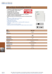
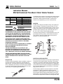
Cutler-Hammer P49880 Rev 01 Instruction Manual: E58 Self-Contained Thru-Beam 18mm Tubular Sensors Models covered in this manual: Sensor Type Mode Emitters Receivers Light Sense (N.C.) Dark Sense (N.O.) AC/DC Models E58CAL18A2E2 E58CBL18A2C2 -E58CAL18A2C2 -- DC-only Models E58CAL18T110E2 E58CBL18T110C2 (NPN) E58CBL18T111C2 (PNP) E58CAL18T110C2 (NPN) E58CAL18T111C2 (PNP) WARNING THESE PRODUCTS ARE NOT DESIGNED, TESTED, OR RECOMMENDED FOR USE IN HUMAN SAFETY APPLICATIONS. USE #4 MOUNTING HARDWARE ONLY! LARGER HARDWARE WILL DAMAGE THE SENSOR AND MAY CREATE AN ELECTRIC SHOCK HAZARD. TIGHTEN THE HARDWARE JUST TO THE SENSOR BODY SO NO DEFLECTION OF THE BODY OCCURS. A complete system consists of an emitter and receiver mounted such that the emitter directs its light beam at the receiver and the receiver is aimed to detect the beam. The emitter and receiver can be separated by up to 26.5 meters (80 feet). MOUNTING The E58 sensor features a threaded housing and includes jam nuts and washers. This allows mounting into any 0.75 inch hole or any of the mounting brackets shown on page 4 of this manual. Use caution to avoid cross-threading the jam nuts on the sensor body. Tighten jam nuts to less than 4 Nm (36 in.lbs. or 3 ft.-lbs.) torque to avoid stripping threads. A second mounting method is to use #4 hardware in the 0.125 inch-diameter mounting holes in the flat sides of the sensor. This is ideal for mounting the E58 against a wall, piece of equipment, rail, mounting bracket, etc. DURING INSTALLATION, CORRECT POWER CONNECTIONS MUST BE MADE FIRST TO ENSURE FAIL-SAFE SHORT CIRCUIT PROTECTION OF THE OUTPUTS. REFER TO THE WIRING DIAGRAMS IN THIS MANUAL. DO NOT USE TOOLS TO APPLY TORQUE DIRECTLY TO SENSOR BODY. ALIGN SENSOR BY HAND BEFORE TIGHTENING MOUNTING HARDWARE. THE GAIN ADJUSTMENT POT IS A 3/4 TURN POT. ANY RESISTANCE ENCOUNTERED WHILE ADJUSTING THIS POT INDICATES YOU HAVE REACHED THE ADJUSTMENT LIMIT STOP. TURNING PAST THIS STOP WILL DAMAGE THE SENSOR. USE ONLY A SUITABLE ADJUSTMENT TOOL OR FLAT BLADE SCREWDRIVER WHEN TURNING THE ADJUSTMENT POT. SHARP OBJECTS CAN DAMAGE THE POT AND RESULT IN ELECTRIC SHOCK. Mounting E58 sensor using #4 hardware. Mounting E58 sensor using jam nuts. MOUNTING LOCATION AND SETUP INTRODUCTION An E58 thru-beam photoelectric sensor installation consists of an emitter and a receiver positioned on opposite sides of a detection zone. The emitter emits infrared and visible red light, which is detected by the receiver. The receiver output switches on when this beam of light is either blocked (when set in dark sense mode), or completed (light sense mode). Receiver Emitter Mount the emitter and receiver units so they are aimed directly at each other from opposite sides of the target. (The receiver should be on the dirtier side because the light scattering effect of dirt collecting on the lens is less significant if it takes place at the receiver.) Ensure the area of the target to be detected will block the entire effective beam (see illustration on next page). Apply power to both units. Accurate sensing depends on proper alignment of the emitter and receiver. To begin, the emitter and receiver must be positioned in rough alignment so that emitter light is received by the receiver (check by placing a solid object in front of the emitter beam—the output indicator on the receiver will change state when the object blocks the beam and change back when P49880 Rev 01 Page 2 the object is removed). If the output indicator does not change state, follow one or both of these two rough alignment methods: 1. The emitter emits visible red light. Look at the emitter with your eye positioned close to the reciever. Mount the receiver in the area where the emitter light is brightest. The emitter must be placed within the receiver field of view for the detection system to operate. 2. Place a retroreflector over the lens of the receiver. Look at the reciever with your eye positioned close to the emitter. Mount the emitter in the area where the light reflected from the retroreflector is the brightest. Obtain final alignment by moving the receiver back and forth in the horizontal axis to find the extreme positions where the output indicator on the receiver goes “OFF” (for dark operate models) or “ON” (for light operate models). Position the receiver midway between the two extremes. Repeat this procedure for the vertical axis, then tighten the receiver in place. Now repeat the final alignment procedure for the emitter. The reciever must be placed within the emitter beam pattern (the area containing all the light rays emitted by the emitter). Working Range Receiver Field of View Emitter Beam Pattern Only the emitter light rays that travel in a straight line to the receiver (the diameter of the lens) will be detected. An object must fully block this beam in order to be detected. Effective Beam Diameter (Detection Zone) WIRING DIAGRAMS For wiring cable versions, the color codes shown are the actual wire colors emanating from the sensor. AC/DC Models (AC Connection) AC/DC Models (DC Connection, see Warning above) L2 Load Blue Black* Switched L1 Brown AC/DC Sensor L1 +V DC 15 to 30 V AC 20 to 250 V L2 L1 +V (-) Blue NPN Output (Sink) Brown AC/DC Sensor (-) (-) * Note: No connection when using thru-beam emitters DC Sensor * Note: No connection when using thru-beam emitters (-) +V +V DC 10 to 30 V DC 10 to 30 V Brown Black* NPN Output (Sink) Blue DC Models (PNP Output) +V Load Load Black* * Note: No connection when using thru-beam emitters DC Models (NPN Output) +V PNP Output (Source) Brown Black* Blue DC Sensor Load (-) (-) * Note: No connection when using thru-beam emitters Effective 6/01 P49880 Rev 01 Page 3 SPECIFICATIONS Power Dissipation Output Type Current Switching Capacity 1.5 W maximum VMOS (bi-directional) 300 mA maximum AC/DC MODELS (DC Operation) 15 to 30 V DC (15 to 24 V DC above 55° C/131° F) 1.5 W maximum NPN (sink) 300 mA maximum Voltage Switching Capacity Off-State Leakage Surge Current On-State Voltage Drop 375 V peak maximum 375 V peak maximum 250 µA typical; 500 µA maximum 2 A maximum --- 250 µA typical; 500 µA maximum 2 A maximum 1.8 V at 10 mA; 3.5 V at 300 mA Input Voltage Response Time Short Circuit Protection Light/Dark Operation Temperature Range Material of Construction Cable/Connector Vibration and Shock Indicator LED Sunlight Immunity Enclosure Ratings Approvals AC/DC MODELS (AC Operation) 20 to 264 V AC, 50/60 Hz 10 µA maximum 1 A maximum NPN: 400 mV at 10 mA, 1.5 V at 250 mA; PNP: 2.8 V at 100 mA 8 mS 3.5 mS Sensor will turn off immediately when a short or overload is detected (Indicator LED will flash). Turn power OFF and back ON to reset. IMPORTANT: During installation, correct power connections must be made first to ensure fail-safe short circuit protection of the outputs. By receiver model Operating and Storage: -40° to +70° C (-40° to +158° F); Thru-beam Emitter: -4° to 158°F (-20° to 70°C) Lens: Polycarbonate; Cable jacket: PVC; Body: Structural polyurethane foam (do not expose to concentrated acids, alcohols, or ketones) 3-meter cable, 3-wire Vibration: 30 g over 10 Hz to 2 kHz; Shock: 100 g for 3 mS 1/2 sinewave pulse Emitter: Lights when powered in ON; Receiver: Lights steady when output is ON; Flashes when short circuit protection is in latch condition 10,000 foot-candles NEMA 1, 2, 3, 4, 4X, 6, 12, and 13 Our products conform to NEMA tests as indicated, however, some severe washdown applications can exceed these NEMA test specifications. If you have questions about a specific application, contact our Applications Department. UL recognized, CSA approved, CE compliant OPTICAL PERFORMANCE RANGE (m) 0.03 0.3 3.0 30.5 1000 EXCESS GAIN All optical specifications are guaranteed to be the minimum performance under clean conditions of any product delivered from stock. Typical performance may be higher. 100 Dirt in the environment will affect optical performance by reducing the 10 amount of light the control receives. For best results, sensors should be used at distances where excess gain 1 is higher than 1.5 (1.5 times the 0.1 1 10 100 amount of sensing power required RANGE (feet) to detect an object under ideal conditions). Higher excess gain will allow the sensor to overcome higher levels of contamination on the lens. All ranges and excess gain graphs are based on a 90% reflectance white card. Source Sensing: Infrared, 880 nm Alignment: Visible red, 660 nm Maximum Range 80 feet Optimum Range 0 to 40 feet Field of View 40 inch diameter at 40 feet Effective Beam 0.25 x 0.625 inches Effective 6/01 DC-ONLY MODELS 10 to 30 V DC (10 to 24 V DC above 55°C/131° F) 1 W maximum NPN or PNP PNP (source): 100 mA maximum; NPN (sink): 250 mA max. (120 mA max. above 55° C/131° F) 30 VDC maximum APPROXIMATE DIMENSIONS (Shown in inches except where noted) Gain Adjustment (Recievers Only) 0.125 Diameter Thru Holes (2 places) Use #4 Hardware Only Indicator LED Cable (3m) 0.47 0.11 0.32 Sensor Type Emitters Receivers 0.65 1.00 “A” A 2.75 2.60 B 1.10 0.25 “B” M18x1.0 Thread(mm) (fits into a 0.75 inch hole) P49880 Rev 01 Page 4 MOUNTING BRACKETS Mounting Bracket Allows a minimum adjustment range. Sensor mounts with two jam nuts (included with sensor). E57KM18 L-Shaped Bracket Two per package. Allows a minimum adjustment range. Sensor mounts with two jam nuts (included with sensor). Chromate finish aluminum 6161A-6501 L-Shaped Bracket with Slot Bulk Two per package (order quantity will be sent bulk packed). Allows installation of sensor with jam nuts in place on sensor body. 6161AS7050 Flat Bracket Allows a minimum adjustment range. Sensor mounts with two jam nuts and washers (included with sensor). Chromate finish aluminum 6161AS5295 Flush Mount Bracket Contoured design with no alignment adjustment. Sensor mounts with #4 studs. 304 stainless steel 616AS5296 Flush Mount Bracket Same as above except with contour. 304 stainless steel 616AS5297 Adjustable Bracket Locking vertical and horizontal adjustments for independent adjustments in each axis. Sensors is electrically insolated from mounting surface. Sensor mounts with two jam nuts and washers (included with sensor). 304 stainless steel E58KAM18 Ball Swivel Bracket Allows 360 degree rotation and 10 degree vertical tilt. Made from Noryl . 6181AS5200 18mm Ball Swivel Bracket Allows 360 degree rotation and 10 degree vertical tilt. Suitable for use with any 18mm threaded sensor. Made from 5% glass filled Valox. E58KAM18B Still Need Help? Contact the Cutler-Hammer Sensor Application Engineers 1-800-426-9184 Fax: 425-513-5356 Cutler-Hammer 720 80th Street SW Everett, WA 98203-6299 425/513-5300 Fax: 425/513-5302 www.cutlerhammer.eaton.com Effective 6/01 Printed in U.S.A.