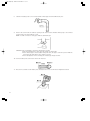
1
OM-148(in/E) 09.2.25 9:03 AM ページ b
Instantaneous Oil-Fired Water Heater
Installation Manual
MODEL
OM-148
(Type D)
IMPORTANT
THIS APPLIANCE SHOULD BE INSTALLED BY A LICENSED, AUTHORIZED PERSON(S) DUE TO THE
NECESSITY OF MAKING ELECTRICAL, WATER AND FUEL CONNECTIONS. RETAIN THIS MANUAL FOR
FUTURE REFERENCE. CHECK LOCAL CODES AND ORDINANCES FOR PERMITTED USE.
CAUTION
THIS WATER HEATER SHALL NOT BE USED FOR COMMERCIAL USE OR FOR ANY PURPOSES OTHER
THAN HOT WATER SUPPLY USES. OTHER USAGE MAY CAUSE A MALFUNCTION OR SHORTEN ITS
SERVICE LIFE. DO NOT REMOVE THE RATING PLATE AND LABELS FROM THE WATER HEATER UNIT.
CONTENTS
SECTION A:
Safety Tips for Installation ⋯⋯⋯⋯⋯⋯⋯⋯⋯⋯ 1
SECTION B:
Unpacking ⋯⋯⋯⋯⋯⋯⋯⋯⋯⋯⋯⋯⋯⋯⋯⋯⋯ 2
Standard Installation Parts ⋯⋯⋯⋯⋯⋯⋯⋯⋯⋯ 2
Accessory Parts ⋯⋯⋯⋯⋯⋯⋯⋯⋯⋯⋯⋯⋯⋯⋯ 2
Dimensional Outline⋯⋯⋯⋯⋯⋯⋯⋯⋯⋯⋯⋯⋯ 3
SECTION C:
Installation
Selecting a Location ⋯⋯⋯⋯⋯⋯⋯⋯⋯⋯⋯ 4
Tools Needed for Installation ⋯⋯⋯⋯⋯⋯⋯ 4
Fuel Tank Installation ⋯⋯⋯⋯⋯⋯⋯⋯⋯⋯⋯ 5
Removing Air Trap ⋯⋯⋯⋯⋯⋯⋯⋯⋯⋯⋯⋯ 6
Temperature and Pressure Relief
Valve Installation ⋯⋯⋯⋯⋯⋯⋯⋯⋯⋯⋯ 6
Permanent Wiring Installation ⋯⋯⋯⋯⋯⋯⋯ 6
Plumbing ⋯⋯⋯⋯⋯⋯⋯⋯⋯⋯⋯⋯⋯⋯⋯⋯ 7
Installation of Unit and Flue Pipe⋯⋯⋯⋯⋯⋯ 9
SECTION D:
Test Run
Preparation ⋯⋯⋯⋯⋯⋯⋯⋯⋯⋯⋯⋯⋯⋯⋯ 12
Operation ⋯⋯⋯⋯⋯⋯⋯⋯⋯⋯⋯⋯⋯⋯⋯⋯ 12
SECTION E:
Chimney Installation ⋯⋯⋯⋯⋯⋯⋯⋯⋯⋯⋯⋯ 13
OM-148(in/E) 09.2.25 9:03 AM ページ 1
SECTION A:
SAFETY TIPS FOR INSTALLATION
BE SURE TO FOLLOW THE FOLLOWING INSTRUCTIONS.
The instructions which are contained in this manual are classified into the following two types, which are
"WARNING" and "CAUTION". These instructions are intended to provide important information for safe
operation.
"WARNING" indicates the possibility of causing the user a fatal accident or serious injury if the water heater
is incorrectly operated.
"CAUTION" indicates the possibility of causing the user injuries or material damages if the water heater is
incorrectly operated.
WARNING
1.
Never use any fuel other than ASTM (AMERICAN SOCIETY FOR TESTING AND MATERIAL) D3699 1-K
Kerosene, D396 Low Sulfur No. 1 Fuel Oil, or ASTM D975 Ultra Low Sulfur Diesel (ULSD). You are recommended to use the low sulfur fuel.
NEVER USE GASOLINE! Use of such fuels can result in an explosion and/or fire and cause injury.
2.
Improper installation, adjustment, modification, or service and maintenance by an unauthorized person
may cause SERIOUS UNIT DAMAGE, BODILY INJURY, HAZARD OR PROPERTY DAMAGE. This unit
should be installed by a licensed, authorized person(s) due to the necessity of making electrical, water
and fuel connections. Refer to the installation manual and the operation and maintenance instructions
for assistance, or consult your dealer for further information.
3.
HAZARD OF ELECTRICAL SHOCK! Before removing any access panels of water heater for service, make
sure the electrical supply to the water heater is shut off. Failure to do this may result in HAZARD, SERIOUS BODILY INJURY, OR PROPERTY DAMAGE.
4.
Check and comply with all local, state and ANSI Z21.22 codes that may apply to water heater(s) before
beginning the installation.
5.
This water heater is designed to be used no more than 4,922 FT. (1,500 m) above sea level. When the
water heater is installed with the flue pipe at altitude of higher than 1,640 FT. (500 m) ~ 4,922 FT. (1,500
m) above sea level or is installed with the chimney adapter at altitude of higher than 3,280 FT. (1,000 m)
~ 4,922 FT. (1,500 m), adjustments are needed.
Ask your local dealer.
The water heater may have a failure of combustion at a high altitude.
6.
RISK OF INDOOR AIR POLLUTION AND FIRE. Be sure the exhaust pipe is properly installed and connected. Aluminum tape provided may be used for sealing exhaust pipe connections.
CAUTION
1
1.
Keep the area around the unit clean and free of flammable materials.
2.
RISK OF FIRE AND ELECTRIC SHOCK. Do not apply any excessive force or pressure to the power supply
cord. Make sure the plug is free of dust. Be sure plug fits the receptacle securely.
3.
Install a temperature and pressure relief valve on the installation mouth in accordance with local, state
and ANSI Z21.22 codes. See the page 6 for more details.
4.
When No. 2 fuel oil is used in an area where the temperature becomes less than 25˚F (-4˚C), it is recommended the use of an additive with the fuel to prevent congealing. Check with a fuel supply company
for the proper additive and mix.
OM-148(in/E) 09.2.25 9:03 AM ページ 2
SECTION B:
UNPACKING
UNPACKING
1.
2.
3.
Unpack the unit carefully.
Check to see if there are any loose screws that may have occurred in transit.
Take accessories and the instruction manual out of the carton.
STANDARD INSTALLATION PARTS
The following standard installation kits are available:
• Outside venting
Use Flue Pipe Installation Kit (Part# 20476440)
• Chimney Venting;
Use Chimney Installation Adapter Kit (Part# 20476430-Dia.5" / #20476415-Dia.4")
For alternate installation methods, you may need to purchase additional accessories which are available
from your dealer.
FLUE PIPE INSTALLATION KIT
(Part#20476440)
Outer flange
(Part#20476469)
ø3-15/16"
(ø100mm)
ø2-13/16"
(ø71mm)
Inner flange
(Part#20476468)
ø2-3/4"
(ø70mm)
CHIMNEY INSTALLATION
ADAPTER KIT
(Part#20476430 - Dia. 5")
(Part#20476415 - Dia. 4")
Flexible
exhaust
pipe (1pc.)
13-3/4"(350mm)
10-1/2"
(266mm)
9-7/8"
(250mm)
EXHAUST PIPE
ADAPTER
Outer flue pipe (1pc.)
Inner flue pipe (1pc.)
Flexible bent joint (1pc.)
(Part#20476401)
(Part#20476492)
Flange gasket
(t:5mm)(2pcs.)
(Part#20476471)
or
33-1/2"(850mm)
39-3/8"(1000mm)
Aluminum tape
(w:30mm´500mm)
(1pc.)
Self tapping screw
(8pcs.)
Insulating
cloth cover
(Part#20476455)
INTAKE PIPE TOP
Inlet hose
ø3"(ø75mm)
(Part#20476451)
Self tapping screw
for concrete
(8pcs.)
Screw
(2pcs.)
Hose band
(2pcs.)
(Part#20476477)
Rubber joint
(2pcs.)
(Part#20476475)
Nut
(2pcs.)
ACCESSORY PARTS (OPTION)
EXTENSION PIPE KIT
(Part#20476496)
EXTENSION FLUE PIPE
(Part#20476486)
31-3/4"~57" (805~1450mm)
9-1/2”(240mm)
CAUTION: Total length of the
extension
pipe
between the water
heater and the flue
pipe must be no
greater than 10ft. with
a total of three bends.
NOTE:
When using extension pipes always
cover the exhaust
pipe with the insulating cloth cover.
ø2-3/4"
(ø70mm)
ø2-13/16"
(ø71mm)
Extension pipe "B" (2pcs.)
Extension pipe "A" (2pcs.)
ø2-13/16"
(ø71mm)
Pipe fixing bracket
(4pcs.)
5-7/8"
(150mm)
5-7/8"
(150mm)
ø2-3/4"
(ø70mm)
Bent joint (2pcs.)
(Part#20476461)
Aluminum tape
(2pcs.)
33-1/2"(850mm)
Insulating cloth cover
(2pcs.)
(Part#20476455)
Self tapping Screw
screw(5pcs.) (4pcs.)
NOTE:
This extension flue
pipe is for use in wall
thickness from 105/8 in. (270mm) to
18-1/8 in. (460mm).
Nut
(4pcs.)
2
OM-148(in/E) 09.2.25 9:03 AM ページ 3
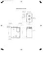
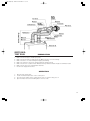
DIMENSIONAL OUTLINE
Exhaust Outlet
2-3/4"( 70mm)
5-1/8"
5-1/8"
(130mm) (130mm)
5-1/8"
5-1/8"
(130mm) (130mm)
8-1/2"
(215mm)
22-1/2"(570mm)
6-1/4"
(160mm)
Hot water Supply
Outlet
(NPT 3/4) Male
Water Supply
Inlet
(NPT 3/4) Male
3/16"
(5mm)
Air Intake Inlet
2-3/4"( 70mm)
12-5/8"(320mm)
Access Cover
Temperature and
Pressure Relief Valve
Installation Opening
(NPT 3/4) Female
3/4"
(19mm)
23"(585mm)
27-3/4"(705mm)
Front Panel
Junction Box
Drain Outlet
(NPT 1/2) Male
3
OM-148(in/E) 09.2.25 9:03 AM ページ 4
SECTION C:
INSTALLATION
WARNING: This unit must be installed in accordance with these instructions, local codes, ordinances and/or
in the absence of local codes, the latest edition of the national fire protection association
(NFPA31) code.
Check and comply with all state, local codes and ANSI (AMERICAN NATIONAL STANDARD
INSTITUTE) Z21.22 that may apply to water heater(s) before beginning the installation.
This unit should be installed by a licensed, authorized person(s) due to the necessity of making
electrical, water and fuel connections.
SELECTING A LOCATION
CAUTION: When No. 2 fuel oil is used in an area where the temperature becomes less than 25˚F (-4˚C), it is
recommended the use of an additive with the fuel to prevent congealing. Check with a fuel supply
company for the proper additive and mix.
Select a place to install the water heater where water and electric supply are easily available.
1.
Select a place which is free of moisture, water spills, pools or snow.
2.
Select a place which draining can be done easily.
3.
Select a place which the fuel tank can be installed safely.
4.
Select a place which is free of combustible substances.
5.
The surrounding walls should be finished with noncombustible materials (concrete block, mortar, or
plaster are allowable).
6.
The floor on which the water heater is installed must prevent intensive vibrations or shock and must be
strong enough to bear the weight of the water heater.
7.
Select a place where proper maintenance and control can be provided for the unit after installation.
8.
Select a place sheltered from weather.
9.
Install the unit on a noncombustible surface in a stable position. If installing on combustible floor, the
unit should be raised off the floor to prevent contact with combustible materials.
10. It is important to keep enough clearance for the purpose of maintenance, repair and possible servicing.
11. The flue pipe is free of snow, icing, leaves, bird's nest or strong drafts.
12. Before making a hole in your wall for the flue pipe, make sure the area is free of electrical wires, gas
pipes and other obstacles.
TOOLS NEEDED FOR INSTALLATION.
Tool
Use
Phillips Head Screwdriver
Electric Drill
Hole Saw, 4-3/4" diameter
Pipe Wrench
Installation of flue pipe, etc.
Drilling hole in wall for flue pipe
Making hole in wall for flue pipe
Connecting fuel pipe
4
OM-180(in/E) 11.5.24 1:16 PM ページ 5
OM-180
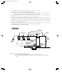
FUEL TANK INSTALLATION
The fuel tank must be purchased separately and installed by a qualified fuel supply technician.
NOTE:
Fuel tank installation must comply with National Fire Protection Association Code NFPA 31 or locally applicable codes. Check with local building officials.
The following instructions should be followed for installation of a large capacity, gravity-fed fuel tank.
¡ Installation height of tank's fuel outlet should be at least 16 in. above floor surface upon which the water
heater rests.
¡ To avoid excess fuel pressure to water heater, the top of fuel tank should be no more than 8-1/2 ft. above
the bottom of the unit.
¡ The inlet fuel pressure must not exceed 2.5 PSI. If the inlet pressure exceeds 2.5 PSI, a pressure reducer
(Part #10005099) must be used.
¡ Fuel tank should be located at least 6 ft. away from all heat sources.
¡ 3/8" OD copper tubing should be used for the fuel line.
¡ To prevent air locks in the fuel line, the fuel line should be smooth with no inverted U-shaped line or
sharp bends.
¡ Install a UL listed fuel filter at the fuel tank outlet. Shut-off valves should also be installed on the fuel line
and connected to the tank as shown below. Unit should have a separate fuel line from fuel tank.
NOTE:
1.
2.
3.
An additional shut-off valve installed next to the exterior wall will minimize the amount of fuel to be
drained should the water heater need to be disconnected. If the valve is inside the building, a
fusible link type (Part #10005597) is recommended.
All external tank must be vented.
Install a UL listed fuel filter at the fuel tank outlet.
Specifications required of this fuel filter are as follows:
Type of Fuel: ASTM D3699 1-K kerosene, ASTM D396 Low Sulfre No. 1 or No. 2 Fuel Oil, or ASTM D975
Ultra Low Sulfur Diesel (ULSD)
Rated Filtering Capacity: 2 GPH (Minimum)
The fuel supply tank must be positioned as to allow gravity feed to the unit and high enough to reduce
trapped air in the fuel line. Please refer to Section “D”, page 8 in the Operation and Maintenance
Instructions for the procedure to remove trapped air. (✽)
NOTE: If the maximum height is exceeded, a fuel pressure limiting valve is required. Part No.
10005099 has 3/8 in. (N.P.T.) inlet and outlet female openings to accept the fuel line fittings.
NOTE: Fusible Link Valve (#10005597)
¡It is most important that the valve, depending on its use, be fully opened or fully closed.
¡The top nut on the valve (below the turn handle) is sealed and should never be tightened or
removed.
¡When installing fuel lines to the valve, be sure to check for fuel leakage.
¡A LEAKING VALVE SHOULD ALWAYS BE REPLACED.
Outdoor fuel tank
Tank vent
Fuel filter
8-1/2 ft. maximum
Fusible link valve
(✽)
Shut-off valve
Loop
Shut-off valve
3/8in. OD copper tubing
5
OM-180-K.indd 6
12/07/13 14:55
OM-148(in/E) 09.2.25 9:03 AM ページ 6
REMOVING AIR TRAP
When operating for the first time or when refueling an empty tank, air may be trapped in the fuel line, making ignition difficult. In this situation, after removing the trapped air thoroughly from the fuel filter at the fuel
tank outlet, follow the procedures below:
1.
2.
3.
4.
5.
6.
Press "POWER SWITCH" to "OFF" position. Disconnect the power supply
cord.
To catch the fuel which will drain out, put a small container under the strainer.
Loosen the screw on top of the strainer. Immediately wipe off any spilled
fuel.
Remove the trapped air thoroughly. Failure to remove all the air will cause
improper ignition and may extinguish the unit.
Tighten the screw after removing trapped air.
Plug into the receptacle. Press "POWER SWITCH" to "ON" position.
NOTE: In the event of an ignition failure, press "POWER SWITCH" to "OFF" position and after 10
seconds press "POWER SWITCH" to "ON" position once again.
TEMPERATURE AND PRESSURE RELIEF VALVE INSTALLATION
At the time of installation, a temperature and pressure relief valve complying with the standard for Relief
valve for Hot Water Supply System, ANSI, shall be installed in the threaded opening provided on the water
heater for the temperature and pressure relief valve. Local codes should govern the installation of the relief
devices.
Specifications required of this temperature and pressure relief valve are as follows:
Inlet (male): 3/4 in.
Temperature relief: 210°F
Pressure relief setting: 150PSI
Rated capacity: Min. 148,000 BTU/H
(a) No other valve is placed between the relief valve and the water heater.
(b) Discharge from the relief device is routed to a suitable place for disposal when relief occurs.
(c) No reducing coupling or other restrictions are installed in discharge line.
(d) Discharge line is installed to allow complete drainage for the device and line.
Note: Manual operation of pressure relief valves should be done at least once a year.
PERMANENT WIRING INSTALLATION
WARNING: RISK OF FIRE AND ELECTRIC SHOCK. Make sure the power supply cord is disconnected to
avoid any electric shock before servicing. Electric shock may cause serious injury. It is recommended that installation should be conducted by a licensed electrician.
6
OM-148(in/E) 09.2.25 9:03 AM ページ 7
BE SURE TO FOLLOW THE FOLLOWING PROCEDURE
POWER SOURCE: 120V AC, 60Hz single phase
1.
Disconnect power supply cord from power source.
2.
Remove four (4) screws and junction box cover on the left
side of unit.
3.
Disconnect ground wire (green) from the power supply cord
bracket.
4.
Disconnect two power supply wires from upper side of the
terminal.
5.
Squeeze strain relief with the adjustable pliers to remove plastic bushing from the unit. Remove the power supply cord.
6.
Replace the strain relief bushing to the power supply cable
and insert the cable into the hole of the left side of unit.
Connect the ground wire to the power supply cord bracket
and power wires to the terminal.
7.
Affix the junction box cover to the unit and insert screws.
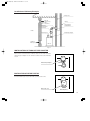
PLUMBING
COLD AND HOT WATER PLUMBING
WARNING: Plumbing should conform to proper plumbing methods, and in conformance with local codes
or regulations.
A licensed plumber familiar with local codes and ordinances should install the OM-148.
CAUTION:
1.
2.
3.
7
An ANSI listed temperature and pressure relief valve should be installed at the hot water outlet
connection of the heater at the time of installation. Local codes should govern the installation
of the relief devices. See page 6 for a temperature and pressure relief valve specifications.
If a check valve or one-way valve is required on the cold water supply line, it is recommended
that an expansion tank (100 psi, 8 gal Min.) should be installed on the hot water supply line.
When the unit is to be installed as a replacement water heater, it is important to determine
whether a check valve has been installed or not.
Remove the check valve before installation of the unit unless a check valve is required by local
code.
In order to prevent the water heater from being damaged or developing a leak, regardless of
being used in a cold, warm or hot region, the cold water supply piping, hot water supply piping, drain pipe, check valve, valves, expansion tank, and temperature and pressure relief valve
should be protected with sufficient insulation materials (by wrapping with heat insulation or by
equipping with a freeze prevention heater).
A water softener is recommended in regions where hard water may be a concern.
Use the following water quality.
Description
pH
Chloride
Hardness
Residual Chlorine
Maximum Levels
6.5 to 8.5
50 mg/L
150 mg/L
2 mg/L
Do not apply any heat to the unit nipples.
OM-148(in/E) 09.2.25 9:03 AM ページ 8
4.
5.
Use standard copper alloy unions and nipples for the connections to the unit.
Copper piping is recommended for the hot water supply line.
Note: Refer to local codes when considering piping materials. Steel piping is not recommended as it
may cause rust in the piping. Use NPT for piping of hot and cold water.
6. Connecting plumbing to the unit, hold unit fittings securely with a wrench to prevent damage to the
unit.
7. Installation of a water strainer and the air release valve is recommended.
8. The distance between the water heater and places where hot water is used should be as short and direct
as possible, and a uniform pipe size of sufficient diameter to carry the full capacity of hot water should
be used.
9. Be sure to connect the water inlet and the hot water outlet as shown on the water heater. Reversing the
two connections will damage the unit.
10. When hot water flows through the supply line there is an inevitable heat loss, regardless of type of
water heater. Thus, insulation or protection of hot water piping is encouraged.
11. Flush the piping before connecting to the unit.
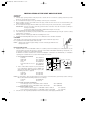
Plumbing Example
Air release valve
Cold water supply line
Hot water supply line
Shower
Shower Room
Washroom
Kitchen Temperature
and pressure
relief valve
Drain
pipe
Union
Water
supply
valve
BS-36UFF
Cold and hot water
mixing faucet
more than 4in.
Strainer
Drain
valve
Base
(Non-combustible
material)
Drain
CAUTION:
¡Do not allow pipes or valve to freeze.
¡Refer to PREVENTING FREEZE UP on Page 10 of the instruction manual.
¡Do not use the unit as an auxiliary heat source for a solar hot water heater, nor hydronic
heating.
8
OM-148(in/E) 09.2.25 9:03 AM ページ 9
INSTALLATION OF THE UNIT AND FLUE PIPE
SAFETY TIPS
WARNING:
1. The flue pipe opening must be fully exposed to outside air. Do not vent into a garage, basement, under
the floor, or into any enclosed area.
2. Do not install the flue pipe in close proximity to other objects or materials.
3. Before making a hole in your wall for the flue pipe, make sure the area is free of electrical wires, gas
pipes and other obstacles.
4. Do not install the flue pipe where it will be exposed to heavy snow, collected leaves, or strong winds.
IMPORTANT: In areas of heavy snow fall, ground surface clearance must be increased according to
average snow falls.
In open areas with strong wind, a wind breaker may be necessary.
5. Do not install the flue pipe below the water heater.
6. The exhaust pipe should be properly installed and connected. Aluminum tape may be used for sealing
exhaust pipe connections.
7. Always cover the exhaust pipe with the insulating cloth cover.
8. If installed in building without an eave, a non-combustion eave should be installed.
CAUTION:
Total length of the extension pipe between the water heater and the flue pipe must
be no greater than 10 ft. with a total of three bends.
NOTE:
When using extension pipes always cover the exhaust pipe with the insulating cloth cover.
INSTALLATION OF UNIT
1. Install the unit on a noncombustible surface in a stable position. If installing on a combustible floor, the
unit should be raised up off the floor to prevent contact with combustible materials by using brick, concrete block or similar non-combustible material.
If minimum clearances between the unit and combustible construction are maintained, no ventilation
openings are needed in the closet door when installed in a closet.
¡ UNIT (INDOOR CLEARANCE)
Left side
Right side
Rear side
Front
From front door to closet
Top
6 in. (150 mm)
6 in. (150 mm)
6 in. (150 mm)
2 ft. (600 mm)
6 in. (150 mm)
2 ft. (600 mm)
more than 2ft.
Intake
(600mm)
Combustible
air
Flue pipe top
Exhaust more
object
more than 2ft.
gas
than 2ft.
(600mm)
(600mm)
Combustible more
more
object than 2ft. than 2ft.
Exhaust
gas
(600mm) (600mm)
Intake
air
more than 2ft.
(600mm)
more than 6 in.
(150mm)
Combustible object
Combustible object
¡ If the combustible material is protected with
non-combustible material such as 0.024 (24gage) sheet metal with ventilated air space, the
following clearance is applied.
Left side
2 in. (50 mm)
Right side
2 in. (50 mm)
Rear side
2 in. (50 mm)
NOTE: It is important to keep enough clearance for the purpose of maintenance, repair and possible servicing.
We recommend the following clearance for servicing.
Left side
2 ft. (600 mm)
Front
5 ft. (1.5 m)
¡ FLUE PIPE (OUTSIDE CLEARANCE)
From flue pipe top to combustible surface: Vertical
24 in. (600 mm)
From flue pipe top to combustible surface: Horizontal
24 in. (600 mm)
¡ EXTENSION EXHAUST PIPE
From extension exhaust pipe to combustible surface: Vertical
3 in. (76 mm)
From extension exhaust pipe to combustible surface: Horizontal
3 in. (76 mm)
2. Check local codes regarding installation of the water heater, water piping and fuel tank.
9
OM-148(in/E) 09.2.25 9:04 AM ページ 10
INSTALLATION OF FLUE PIPE
IMPORTANT: Check and comply with all state and local codes that may apply to water heater before beginning installation.
1. Select unit location. Allow clearances as indicated above between the unit and all other materials
2. Make sure that the outside area to where the flue pipe will reach is clear of any objects.
NOTE: For wall thickness greater than 10-1/2 inches, a flue pipe extension is available. See page 2 for
details. Flue pipe can be installed through any standard building materials. Please ask your
local dealer or distributor for more details.
3.
For standard installation, position the hole for the flue pipe.
NOTE: The water heater should be installed on a sturdy floor that is level and flat.
4.
Cut the hole for the flue pipe from inside the room. Use a 4-3/4" diameter hole saw attached to an electric drill. The opening on the inside wall should be slightly higher than the outside opening (approximately 1/4") so that the flue pipe will slope slightly downward (approximately 3 degrees) after it is
installed. This will enable condensed moisture to drain from the flue pipe to the outside and prevent
rain or snow from entering from outside after installation.
5.
Install the inner flange and the flange gasket to the inner flue pipe and insert the inner flue pipe through
the wall hole from inside the room. Make sure the arrow on the inner flange is pointing up and secure
the securing band with a screw and a nut through two holes of the fixing band. Secure the inner flue
pipe to the wall with the four screws provided with the unit.
Inner flange
screw
Inner flue pipe
Flange gasket
Self tapping screw
6.
Nut
Install the flange gasket to the outer flue pipe. Secure the outer flue pipe to the wall by turning it clockwise. This locks the two halves together.
NOTE: Make sure to secure the outer flue pipe well.
Outer flue pipe
Flange gasket
Inner flue pipe
7.
Insert the flexible exhaust pipe to the flexible bent joint until it locks. Insert the flexible bent joint to the
exhaust opening of the inner flue pipe until it locks.
NOTE: The flexible exhaust pipe and flexible bent joint have claws to prevent them from being separated. When connecting them, raise the claws a little.
These claws may be raised already depending on production lots. If this is the case, insert them
as they are. Do not attempt to draw a pipe off in any event while the claw is raised. Otherwise,
it could leak the exhaust gas.
Tab
Flexible
bent joint
Raise the claw a little
with pliers or the like.
Inner flue
pipe
Tab
Flexible
exhaust pipe
Flexible bent joint
Approx.
3 mm
10
OM-148(in/E) 09.2.25 9:04 AM ページ 11
8.
Slide the insulating cloth cover over the flexible exhaust pipe and the flexible bent joint.
Insulating
cloth cover
9.
Remove the screw from the exhaust opening of the unit. Insert the flexible exhaust pipe to the exhaust
opening and secure them with the screw.
NOTE: Seal all connections of the pipes with the aluminum tape.
CAUTION: ¡Do not attempt to insert the exhaust pipe forcibly.
¡If O-ring is damaged, it could cause the leakage of exhaust gas.
¡If the exhaust pipe is inserted after raising the claw, the pipe is locked in position with the
claw so that the pipe will become unable to remove.
¡If it is attempted to remove forcibly, the exhaust pipe may be broken.
10. Connect rubber joints to the both ends of the inlet hose.
11. Place the hose bands on the rubber joints and attach the hose as shown below. Tighten the bands.
Hose band
Hose band
11
OM-148(in/E) 09.2.25 9:04 AM ページ 12
" & !
' ( *
('* " ) )#
'( (
!
" # & !
$ " % SECTION D:
TEST RUN
1.
2.
3.
4.
5.
6.
7.
PREPARATION
Make sure the flue pipe is installed properly.
Make sure the fuel tank is installed properly. Make sure there is no fuel leakage.
Make sure there is no water leaking from piping. (Plumbing)
Make sure electrical connections and grounding are wired properly.
Make sure the floor is stable and can withstand strong vibration and the weight of a full water heater.
Make sure the area is free of flammable materials.
Check for air trapped in fuel lines.
OPERATION
1.
2.
3.
4.
Open the fuel supply valve.
Set the hot water temperature on the control panel.
Press the power switch on the control panel to turn on. "Power" lamp goes on.
Open hot water faucet and unit will ignite in a few seconds.
12
OM-148(in/E) 09.2.25 9:04 AM ページ 13
SECTION E:
CHIMNEY INSTALLATION
This unit is a sealed combustion system and as an installation option it may be connected
directly to a chimney. Using this option, room air is used for combustion and the exhaust gases
are vented into the chimney to the outside.
IMPORTANT:
1. This appliance should be installed by a licensed, authorized person(s) due to necessity of
making electrical, water and fuel connections. Check local codes and ordinances and/or the latest
edition of the National Fire Protection Association Standard for the Installation of Oil-Burning
Equipment. NFPA-31.
2.
A Barometric Draft Regulator must be used in the exhaust pipe to stabilize flue draft. It is required
that a UL-listed (Underwriters Laboratories) damper be used. The Barometric Draft Regulator must
be installed in accordance with NFPA-31.
3.
Installation in an unconfined space in buildings of conventional frame, brick or stone construction,
infiltration normally is adequate to provide air for combustion and ventilation.
For confined spaces, openings for air intake and venting must be provided. (See Fig.1.)
Check local codes and ordinances and/or NFPA-31 Code for specific details.
4.
It is recommended that the OM-148 hot water heater be connected to an independent chimney flue.
CAUTION:
1. In case another appliance is connected to the same chimney flue (2 or more units), it may be necessary
to comply with state and local codes. Check with your local dealer or licensed installer.
2.
Connecting the OM-148 hot water heater with two or more appliances using the same chimney flue may
affect the performance of the hot water heater. Check with your dealer for other installation options.
3.
Total length of the exhaust pipe and the chimney liner must be no greater than 25 ft. Maintain the shortest
piping possible by selecting a location as close as posssible to the chimney.
NOTE:
1. To prevent against exhaust leaks, make sure all connections are properly fitted and seal connection with
aluminum tape or heat resistant sealing material.
13
2.
A 5-inch or 4-inch diameter exhaust pipe is used for a chimney installation. To prevent injury due to the
hot surface of the exhaust pipe, be sure to wrap the exhaust pipe with a heat insulator material.
3.
For a chimney installation, use accessory (option) parts.
Chimney Installation Adapte Kit
(Part #20476430 - Dia.5” or Part #20478415 - Dia.4”)
OM-148(in/E) 09.2.25 9:04 AM ページ 14
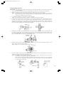
Installation of Chimney Example
Chimney Liner
Intake Air
Outlet Opening
Chimney
Exhaust Pipe
(Dia. = 5 inch/4 inch)
Heat-Resistand
Sealing Matrials
Barometric
Draft Regulator
(UL-listed)
Outside
Intake Pipe Top
Exhaust Pipe Adapter
Outside Air
Intake Opening
OM-148
Fig. 1
INSTALLATION OF EXHAUST PIPE ADAPTER
Remove the screw from the exhaust outlet of the unit. Insert the
exhaust pipe adapter to the exhaust outlet and secure with the
screw.
Exhaust Outlet
Exhaust Pipe Adapter
Fig.2
INSTALLATION OF INTAKE PIPE TOP
Insert the intake pipe top to the intake opening of the unit.
Intake Pipe Top
Intake Opening
Fig.3
14
OM-148(in/E) 09.2.25 9:03 AM ページ a
TOYOTOMI U.S.A., INC.
604 Federal Road, Brookfield, CT 06804
www.toyotomiusa.com
This manual supersedes earlier editions.
PART No.20476691
Rev. 3/09
Printed in Japan
4731003052