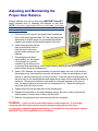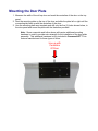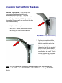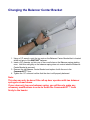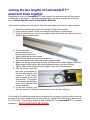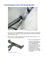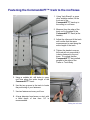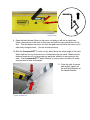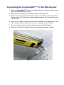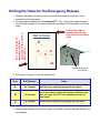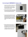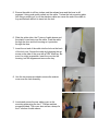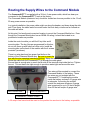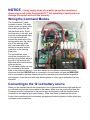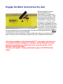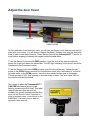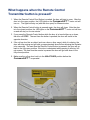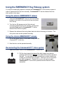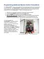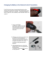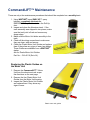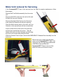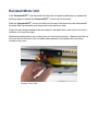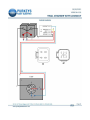
1
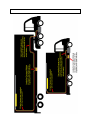
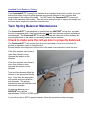
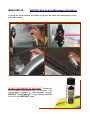
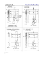
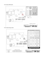
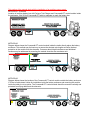
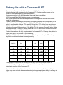
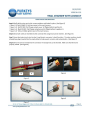
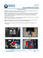
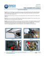
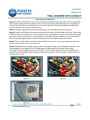
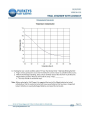
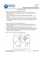
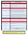
Installation
Manual
WITH AUXILIARY POWER
SUPPLY
UNITED STATES
1 (716) 542-5427
CANADA
1 (905) 333-6745
Issue 120725 (En)
)
BEFORE CALLING FOR TECHNICAL SUPPORT PLEASE
FILL OUT THE INFORMATION BELOW.
COMMANDLIFT SERIAL NUMBER_______________________
DEALER____________________________________________
INSTALLATION DATE_________________________________
DOOR TYPE_________________________________________
DOOR SIZE__________________________________________
DOOR SERIAL NUMBER_______________________________
United States
1 (716) 542-5427
CANADA
1 (905) 333-6745
Issue 120725 (En)
Pre-Installation Check List
1. Before you begin the installation of your CommandLIFT™, confirm that
you have a minimum of 2 inches clearance above the Roll-Up door when it
is in the Open position.
YES
NO
2. Has the correct Balancer been installed on your Roll-Up door? Confirm
that either a WHITING 2376 or 7176 center bracket balancer has been
used.
YES
NO
3. Is the radius of the track suitable for CommandLIFT™ operation? The
CommandLIFT™ might have difficulty with tight radius tracks during the
closing cycle.
YES
NO
4. Is the Roll-Up door balanced properly? Does it work easily, UP and
DOWN by hand?
YES
NO
5. Is the door in good working condition? Make sure there are no broken
panels, hinges or rollers etc.
YES
NO
6. Is the top panel of the door strong enough, or will it require reinforcement
to prevent it from “flexing” during the closing cycle?
YES
NO
7. Is the power supply adequate? Has the battery and charging system
been well maintained?
YES
NO
8. Will a proper power supply always be available? Will a secondary power
supply be required?
YES
NO
9. The CommandLIFT™ is supplied with two Remote Transmitters. Will
that be adequate or will alternative transmitting devices be required?
(Additional Remote Transmitter – Keypad – Key Switch – Activating button
on the dashboard). These items might be useful for dock workers or others
who may need access to the cargo area of the truck or trailer.
YES
NO
If any of the above boxes have been marked “NO”
Do NOT continue with the CommandLIFT™ installation
Before you start the installation
This manual will cover the installation of two primary components, the CommandLIFT power
door opener and if necessary an auxiliary power supply. We have used Purkeys Fleet Electric
power supply which utilizes a Trail Charger charging system and a battery. The Purkeys
installation is covered from page 30 through 44. The auxiliary power supply may be required for
trailer applications. We do NOT recommend connecting the CommandLIFT to a reefer battery without
first consulting with the reefer dealer and Whiting technical support.
POWER REQUIREMENTS:
The CommandLIFT™ is supplied with 32 feet of cable that runs from the CommandLIFT™
track to the Command Module that should be mounted as close to the supply battery as
possible. The installer is required to supply the main power wire that runs from the 12 volt, 20
amp power supply (battery) to the Command Module. An 8 gauge supply wire can be used if
this wire is less than 35 feet in length. This would typically be used in a truck body
application. If the supply wire is 35 feet to 60 feet in length, then a 6 gauge wire must be
used. See the illustration on the next page.
WARNING – The gauge of the supplied cables is determined by the
maximum possible lengths. Do not splice wires for extra length as this can cause
voltage drop resulting in poor / intermittent operation or damage to the system.
Power Consumption:
An idle CommandLIFT™ will draw 1.2 amp hours from a battery over a 24-hour period.
It is recommended that during long periods of inactivity, the CommandLIFT™ be
disconnected from the battery.
1. Using the illustration on the next page, plan how you are going to run the wires for the
CommandLIFT™.
2. Note that the CommandLIFT Module must be located as close as possible to the
source battery. If the cable lengths do not allow this the CommandLIFT module can be
mounted under or inside the vehicle. It must be protected from the extreme conditions
under the vehicle.
It is not recommended, but if you are planning to connect the
CommandLIFT™ to an existing Reefer Unit or Lift Gate – consult with
Whiting Door and the reefer / lift gate supplier first!
Today’s refrigeration units are equipped with sophisticated electronics and control
systems. The integrated logic of these systems monitors the remaining power level of
the battery and isolates accessories when the battery drops below pre-determined
levels. It is strongly recommended that you utilize the Purkeys Trail Charger system to
ensure your new CommandLIFT™ works consistently and doesn’t depend on the
refrigeration system for power.
IMPORTANT! ALWAYS MOUNT BOX WITH WIRE OPENINGS TO THE BOTTOM.
Insulated Truck Bodies or Trailers
If the CommandLIFT™ is going to be installed in an Insulated truck body or trailer, you must
ensure that strips of wood or metal spacers are securely fastened to the roof bows and
extend down to the ceiling of the body. Do NOT fasten the CommandLIFT™ aluminum
track to the insulation in the ceiling. This will not be strong enough to support the weight and
the force that is required to open and close the door.
Twin Spring Balancer Maintenance
The CommandLIFT™ was designed to operate with any WHITING® roll-up door, provided
the door is equipped with a twin spring balancer and the door has been properly maintained
and balanced. The CommandLIFT™ can also be used with other roll-up door systems but
some modifications to the trailer or truck body header may be required.
Check to make sure the roll-up door is properly balanced.
The CommandLIFT™ will operate the roll-up door provided a force of no more than 50
pounds is required to open or close the door.
Ensure that the force required to lift the door is the same force required to close the door.
If the door requires more force to
open than it does to close,
increase the tension on the
balancer.
If the door requires more force to
close than it does to open,
decrease the tension on the
balancer.
Time and the elements affect the
tension on the spring that lifts the
door. Over time, the spring wire
will corrode and loose effective
wire diameter. The springs
themselves also get tired and loose
their tensile strength.
An average balancer on a
WHITING® door will last
approximately 15,000 to 25,000 cycles.
If your roll-up door is NOT in proper balance, follow the procedure on the next page.
Adjusting and Maintaining the
Proper Door Balance
Always lubricate your roll-up door using WHITING® Easy-UP™
spray lubricant prior to checking the balance of the door.
NOTE: If the door is balanced before it is lubricated, it will have
to be “over balanced” in order to overcome the friction of dry
rollers and hinge pins.
1. Fully open the roll-up door and push it back towards the
front of the trailer approximately 18”, this may require the
assistance of another person or a spreader bar placed
between the header and the bottom panel of the door.
2. Install vice grip pliers into the
track at the bottom roller to
hold the door in this open
position while working on the
balancer.
3. The springs should have
equal tension, for this reason
it is important to count the
number of turns either put on
or removed from each spring, this is easily done by placing a mark on the winding
anchor before doing any adjustments.
4. Insert a 3/8” diameter rod (see illustration on previous page) into one of the holes on
the winding cone` and carefully loosen the set screws. Lower the winding bar to add
tension or raise the winding bar to remove tension. Insert the second winding bar into
the next hole on the winding anchor and repeat the process until the desired tension is
achieved. The amount of tension to be added or removed depends on the type of
door, the age of balancer and how far out of adjustment it is. Adjust the springs no
more than one half turn at a time.
5. Tighten all the set screws and remove the winding bars
6. Repeat this procedure on the other Balancer spring. Be sure to add or remove the
same amount of tension as you did on the first side.
7. Remove vice grip pliers from track and test the door operation.
Caution – work on doors and related parts can be dangerous.
It is strongly
recommended that repair service work be performed by persons who have
successfully completed appropriate training. If assistance is required, please contact
WHITING® for a list of qualified service locations.
Mounting the Door Plate
1. Measure the width of the roll-up door and mark the centerline of the door on the top
panel.
2. Rest the mounting plate on the top of the door and slide the plate left or right until the
connecting tab lines up with the centerline of the door.
3. Use the mounting plate as a template and drill only the five (5) holes shown below, in
the door panel and mount the plate with the fasteners provided.
Note: Some composite and hollow doors will require additional mounting
hardware in order to provide extra strength for the installation of the door plate
assembly. This additional hardware is only included in CommandLIFT™ kits
that are manufactured for these types of doors.
Line up with
Centerline
Of Door
Changing the Top Roller Brackets
WHITING® DryFREIGHT™ style roll-up doors
come equipped with regular top closure
assemblies (shown to the right). It may be
necessary to replace the roller slide portion of the
assembly with the Whiting #15886 adjustable top
closure arm. Depending on the truck body this arm
may not be necessary.
1. Fully close the roll-up door.
2. Using a 1/2” wrench, remove the nuts from
the existing top closure slide brackets.
DryFREIGHT™ Top Closure Assembly
3. Replace the brackets with the
adjustable top closure arm and
bracket assemblies and rollers.
4. Make sure the brackets are
installed so that the top panel of
the roll-up door pushes against
the header to ensure a good seal
when the door is closed. Check
to make sure the top door panel
clears the Balancer Brackets.
Note: It is not necessary to change these brackets if you are installing the
CommandLIFT™ on the WHITING® ColdSAVER™ or the TempGUARD™
doors.
Changing the Balancer Center Bracket
1. Using a 1/2” wrench, undo the two nuts on the Balancer Center Bracket that is located
at the mid point of the WHITING® balancer.
2. Insert a 3/8” diameter rod into one of the round holes on the Balancer spring winding
cone. Hold this rod tightly so the balancer spring does not unwind when the Balancer
Center Bracket is removed.
3. Remove the old Balancer Center Bracket and replace it with the one in the
CommandLIFT™ box.
4. Tighten the 1/2” nuts and confirm that the door is still properly balanced.
Note:
This step can only be done if the roll-up door operates with two balancer
springs as shown above.
If your door only has one balancer spring, you will have to make any
necessary modifications in order to fasten the CommandLIFT™ track
firmly to the header.
Joining the two lengths of CommandLIFT™
aluminum track together.
Depending on how your CommandLIFT™ was ordered, the aluminum track will be shipped
in either one or two pieces. If the track was delivered in one piece, continue on to the next
step: Connecting the track to the Header Bracket.
If the track was delivered in two pieces, follow the next steps to join the two tracks together.
1. Remove the black plastic cover from the side of both track sections.
2. Line up the two pieces of track on a straight, level bench or work surface.
3. Using an Allen wrench, undo the six screws (both sides) that are holding the joiner
slides in the rear track section.
4. Pull the two track
joiners halfway out of
the rear track section and
lightly tighten the two front screws
5. Slide the front track over the two joiner pieces
and ensure that the two tracks are butted together snugly.
6. Make sure the two tracks align properly and there are no sharp edges at the joint.
Sharp edges at this location will cause premature wear to the motor sliders.
7. Tighten down all the screws and once again, check for fit and alignment.
8. Find the Sensor wire that
has been pre-installed on
the front track section, and
connect it to the Sensor
that is located in the rear
track section. The position
of this sensor will probably
have to be adjusted later
in the installation.
9. Fit the wire carefully into
the track sections. This Sensor determines how far the door will open.
If the length of the aluminum track has to be reduced for any reason, the cut must be made at
the back of the track (furthest from the door opening). Replace the “Stop Screw” that was cut
off of the track. The shortest length of track required for the CommandLIFT™ to operate
properly is: door height plus 36 inches.
Connecting the track to the Header Bracket
Connecting the track to the header
1. Pick up the front of the CommandLIFT™ track assembly and fasten the adjustable
mounting bracket to the Balancer Center Bracket that you installed on the Balancer
shaft in the previous step.
2. Place the 5/16” nut and bolt through the three pieces and finger tighten the nut. All
the nuts in this area will be tightened later.
Adjustable Header Bracket
3. Adjust the Header Bracket left
or right to ensure the tab on
the top door panel and the tab
on the CommandLIFT™
motor unit are lined up as
closely as possible. Once the
two tabs are lined up, tighten
the adjusting bolts in the
Header Bracket so the track
assembly won’t move while it
is being fastened to the ceiling
or roof bows.
Fastening the CommandLIFT™ track to the roof bows
1. Using “Jack Stands” or some
other suitable method, lift the
front end of the
CommandLIFT™ track up to
the ceiling or roof bows.
2. Measure from the edge of the
body roof to the edge of the
CommandLIFT™ track (at the
header).
3. Adjust the other end of the track
and confirm that the same
measurement is used along the
entire length of the track.
4. Tighten the stands to ensure
the track will not move while it
is being fastened to the roof
bows. It is critical that the
CommandLIFT™ be installed
parallel to the sides of the
Trailer or Truck Body.
5. Using a suitable bit, drill holes in every
roof bow along the entire length of the
CommandLIFT™ track.
6. Use the two grooves in the track to locate
the positioning of your fasteners.
7. Use two fasteners at every roof bow.
8. A large diameter head screw or rivet, with
a head depth of less than 1/4” is
recommended.
Drilling the roof bows
Access Panel
9. Open the black Access Panel on the motor unit and you will see a metal lever.
Insert a screw driver in the hole on this lever and pull the lever towards the roll-up
door. This will release the motor unit from the gears and will allow the motor unit to
slide freely along the track. (See the illustrations above)
10. Slide the CommandLIFT™ motor unit (by hand) along the entire length of the track.
Watch and feel for any obstructions or resistance during the travel. Make sure the
fastener heads are not too large and pay particular attention to any waving in the
track. If the CommandLIFT™ binds because of a wavy track, use shims to make
sure the track is level and straight.
11. Once the track is secure
and straight, tighten all
the nuts and fasteners at
the Header Bracket.
Tighten all fasteners
Connecting the CommandLIFT™ to the Roll-Up door
1. Slide the CommandLIFT™ motor unit towards the door, as far as it will go, then
slide it back approximately 3/4 inch.
2. Make sure the roll-up door is in the fully closed and locked position.
3. Measure the distance between the hole in the tab on the Motor Unit and the hole in
the tab on the Door Plate and cut the threaded connector rod 1” shorter than this
measurement.
4. Install the turn buckle. Tighten the nut on the threaded rod up against one of the
forks on the assemble to prevent the rod from turning itself out from vibration.
5. The turn-buckle assembly should be resting at approximately 45 degrees.
6. Open the roll-up door by hand and confirm that everything operates smoothly.
Drilling the Holes for the Emergency Release
Line up this edge of
template with the
centerline of the second
door panel
1. Measure the width of the roll-up door and mark the centerline of the door on the
second (from the top) panel.
2. Find the paper template in the CommandLIFT™ box. Remove the paper backing
and stick the template to the second panel as described in the illustration on the next
page.
Line up this edge of
template with the top
edge of the second door
panel
Not to Scale
B
A
A
C
B
Second door panel
from the top.
3. Drill holes A, B and C as per the chart below.
Hole
Drill Diameter
Notes
A
3/8” diameter
Drill holes (2) completely through the door panel
B
1/4” diameter
These are clearance holes and should be drilled no more
than 1/4” deep. (Do NOT drill completely through the
door panel).
C
7/8” diameter
Use a hole saw and drill hole through the door panel
4. Remove the template from the door panel if you wish, or mount the plate directly over
the template.
Connecting the EMERGENCY release cable
1. Locate the lock assembly, turn the key 90
degrees and remove the core of the lock from
the lock housing plate. Insert the housing
plate into the holes on the face of the door.
Use masking tape if necessary to hold the
housing to the face of the door.
2. Select the appropriate length screw from the
chart and secure the interior mounting plate to
the housing, ensuring the small holes on the
corners are aligned with the relief holes.
3. Insert the end of the cable with the stop into
the guide tube at end of the motor housing,
push the cable through until you can see it in
the opening where the lever is. Insert the stop
through the release lever and engage the
lever (lock the CommandLIFT), with the lever
engaged push the cable 2” further into the
motor.
4. Slide the cable sleeve over the cable and into
the motor housing 2”. Mark the sleeve 1”
below the door connector plate. Remove the
sleeve and cut it on the mark. DO NOT CUT
THE CABLE. Slide the sleeve back over the
cable and into the motor housing. Use the two
½” Phillips machine screws to secure the
cable clamp to the door connector plate.
5. Ensure the cable is still two inches past the release lever and the lever is still
engaged. Using good quality cutters cut the cable 1” below the lock mounting plate.
Not using a proper tool to cut the stainless cable can cause the end of the cable to
fray and become difficult to insert into the lock.
6. Slide the yellow tube, the 2” piece of cable sleeve and
the plastic cover base over the cable. Push the cable
through the door and lock housing so it protrudes
through the face.
7. Insert the cut end of the cable into the hole on the back
of the lock core. Secure the cable by tightening the set
screw on the side of the core with a 5/64” Allen key. Be
sure it is a tight as possible. Insert the core into the
housing, turn 90 degrees and remove the key.
8. Use the two screws provided to secure the exterior
cover over the lock assembly.
9. Locate and secure the rear cable cover on the
mounting plate using the two 1” Phillips machine
screws provided. This cover also acts as a clamp for
the 2” section of cable sleeve.
Routing the Supply Wires to the Command Module
The CommandLIFT™ is supplied with a 32 foot, 6-wire power cable, which has been preconnected to the CommandLIFT™ track at the factory.
The Command Module (electronic box) should be located as close as possible to the 12 volt,
20 amp power source as possible.
In a typical installation, the power cable might run along the header, and down along the side
wall. From there, the cable would be routed under the truck body or trailer as far forward as
the cable will allow.
At this point, find a safe and convenient location to mount the Command Module box. Even
though the Command Module box has an NEMA 4X rating, it should be located in as
protected a location as possible.
Inside the control module you will find 2 key fobs and 4
mounting tabs. The key fobs are programmed for this box,
do not mix them up with fobs from other units. Install the
mounting tabs on the back of the module with the 4 screws
provided. (as shown)
There is a wire gland and two power feed bolts on the
bottom of the Command Module box. Be sure to mount the
box with the wire openings towards the bottom. Mount the box onto the vehicle.
Route the cable from the CommandLIFT up through the cable gland.
Ensure there is enough wire to reach the far side of the terminal strip inside the box. Tighten
the nut. This nut has to be tight enough to provide a water-tight seal around the wire.
Two wires will be required to connect the
Command Module to the battery. These
two wires are not included with the
CommandLIFT. If installing the module
inside the battery enclosure 10 gauge wire
is adequate, if mounting the module
outside the enclosure minimum 8 gauge
wire is required for up to 35 feet in length.
Over 35 feet will require 6 gauge wire.
NEG FEEDER BOLT
POS FEEDER BOLT
COMMANDLIFT CABLE GLAND
A 30 amp in line fuse should be used on the positive line as close to the battery as possible.
NOTICE - Using supply wires of a smaller gauge than mentioned
above may result in the CommandLIFT™ not operating properly and may
damage the system and void the warranty.
Wiring the Command Module
The CommandLIFT cable
contains six wires. The white,
yellow, brown and green wires
are smaller gauge than the
red and black wires. Study
the illustration to the right, and
route the smaller gauge wires
to the terminal strip and
connect the white wire to the
existing white wire, the yellow
wire to the existing yellow
wire, the brown wire to the
existing brown wire and the
green wire to the existing
green wire.
The red and black wires
should be connected to the
existing red and black wires at
the end of the terminal strip.
Make sure all connections are
solid and secure.
The two battery wires can now
be connected to the feeder
bolts on the bottom of the box. If you have elected to use different colored battery wires,
make sure that the POSITIVE wire is connected to the red feeder bolt and the NEGATIVE
wire is connected to the black feeder bolt and the opposing ends are identified as positive
and negative. Cover the bolts with a die electric grease or other type of protection from the
elements.
Connecting to the 12 volt battery source
When you are satisfied that all the connections to the Command Module are tight and secure
you can now connect the source cables to the battery. Make sure the positive lead from the
Command module is connected to the positive post on the battery and the negative lead is
connected to the negative post on the battery. Make sure these connections are secure.
Protect the connections from the elements by applying die electric grease or some other type
of sealant to the connections.
Engage the Motor Unit and test the door
Before engaging the motors,
position the door so the
CommandLIFT is between the
open and closed sensors. These
are found on the road side of the
CommandLIFT track. Once the
CommandLIFT is between these
sensors you can lock the motor
into position by engaging the drive
lever. Open the black access cover
on the motor unit and you will see
a metal lever. Insert a screw driver
in the hole on this lever and pull
the lever towards the front of the body (away from the door opening) until the lever “SNAPS”
into place at the location shown to the right.
You may have to use a screw driver or other suitable tool to help you move the lever into
place. The motor unit is now locked into place in the track. Replace the access cover.
Check the installation of the CommandLIFT™ once again, and when you
are satisfied that the installation is complete, and all the fasteners and
electrical connections are tight and secure, press the button on the
Remote Control transmitter.
The door will operate. Pressing this button again, will STOP the door
travel.
Adjust the door travel
SENSOR
CABLE SLIDER
On the road-side of the aluminum track, you will see two Sensor Units that are each held in
place with a set screw. You will have to remove the plastic, finishing strip from the aluminum
track in order to see these Sensors. These Sensor Units tell the CommandLIFT™ how far to
travel before stopping by sensing the magnet inside the cable slider.
To set the Sensor for the door CLOSED position, close the door all the way and slide the
sensor so it rests just above the cable slider. The LED light indicating “door closed” should be
illuminated in the Command module.
To set the Sensor for the door OPEN position, open the door all the way. Loosen the set
screw on the OPEN Sensor and slide it in the aluminum track until it rests about 2” in front of
the cable slider. In the OPEN position, the roll-up door should be just clear of the header.
This will provide a FULL door opening on the truck body or trailer. The “door open” LED on
the board should be illuminated.
Don’t forget to place the CommandLIFT™
CAUTION label above the door grab
handle, just above the Pull Strap. This label
reminds operators that the door will
probably not operate normally and that they
must use the Remote Control Transmitter in
order to activate the door, or use the key on the
EMERGENCY Release system in order to
operate the door manually.
What happens when the Remote Control
Transmitter button is pressed?
1. When the Remote Control Door Button is pushed, the door will start to open. After the
door is in the open position, the LED lights on the CommandLIFT™ motor unit will
turn on. The lights will stay on (with the door open) for fifteen minutes.
2. When the Remote Control button is pressed again, the door will close. After the door
is in the closed position, the LED lights on the CommandLIFT™ motor unit will turn
on and will stay on for one minute.
3. If you press the Remote Control button while the door is in travel either up or down,
the door will STOP. The next time the button is pushed, the door will travel in the
opposite direction.
4. If the roll-up door hits an object (such as a box or other cargo) while it is closing, the
door will stop moving and go back up approximately three inches allowing the obstacle
to be removed. The next time the Remote Control button is pressed, the door will go
back to the fully open position. If the door is obstructed while opening it will stop, but
not reverse. The next time the remote is pressed the door will go back down to the
fully closed position.
5. Make sure the roll-up door lock is in the UNLATCHED position before the
CommandLIFT™ is operated.
Using the EMERGENCY Key Release system
You may be occasionally required to release the CommandLIFT™ from the door system in
order to operate the Roll-Up door manually. CommandLIFT™ can be released from the
drive system in two ways.
Using the exterior EMERGENCY release
1. Insert the CommandLIFT™ key into the lock cylinder
located in the center of the second roll-up door panel
from the top.
2. Turn the key 90 degrees and pull the lock and
connecting cable from the lock cylinder. Pull the lock
assembly firmly and the CommandLIFT™ will be
released from the drive system.
3. Reinsert the cable and the lock cylinder back into the lock housing on the door. The
roll-up door can now be operated manually.
Using the interior EMERGENCY release
1. Pull on the yellow section of the cable coming from the
CommandLIFT to the door.
2. Now the door can be operated manually.
Reconnecting the CommandLIFT™ drive system
1. Open the Access Panel on the CommandLIFT™ motor unit.
2. Pull the lever towards the front of the body (away from the door
opening) until the lever “SNAPS” into place at the location shown to
the right. You may have to use a screw driver or other suitable tool
to help you move the lever into place. The motor unit is now locked
into place in the track. Replace the cover on the access panel.
CommandLIFT™ can now be operated with the Remote Control
transmitter.
Integrating Auxiliary Systems with CommandLIFT®
Integration of the CommandLIFT® system with other operating systems may only be done
with express written consent of WHITING Door. Failure to do so will void all warranties.
Consult with your dealer or the factory before connecting any other systems to the
CommandLIFT® controller.
Conditions
Connection must be as outlined in the CommandLIFT® manual as well as the specific
installation instructions from the integrated accessory.
WHITING warranty against manufacturing defects is limited to the CommandLIFT® motor
unit, the control module and any supplied cable.
WHITING Door will not be held responsible for any components or related labour to any
auxiliary systems as a result of integration with the CommandLIFT®.
Damage to the CommandLIFT® controller as a result of connection to an auxiliary controller
is not covered and is the responsibility of the supplier / manufacturer of the secondary
controller.
Under no circumstances can the CommandLIFT® control module be used as a power source
or junction point for any auxiliary systems or controllers.
Damage to the mechanical drive system, track, electronic module or wiring through improper
operation of the CommandLIFT® in conjunction with any auxiliary systems is not covered
under warranty.
Any damage as a result of forcible entry is not covered under the warranty.
WHITING Door reserves the right to review and retract if necessary the consent if the
configuration of the various systems deviates from the original design and approval.
Troubleshooting with Auxiliary Systems
When CommandLIFT® is used with a controller other than the originally supplied
CommandLIFT® FM receiver the first step in any troubleshooting scenario is to check for
power to the CommandLIFT® controller and auxiliary controller.
Once power has been verified the second step is to disconnect the auxiliary inputs to the
CommandLIFT® controller and reinitiate the FM receiver. Test the CommandLIFT® with the
originally supplied receiver and key fob remotes. If the CommandLIFT works with the original
receiver and remotes the problem is with the auxiliary system.
Contact the supplier / manufacturer of that system.
Programming Additional Remote Control Transmitters
The CommandLIFT™ comes with two Remote Control transmitters that are pre-programmed
for your motor unit. The CommandLIFT™ will allow additional Remote Control transmitters
to be programmed to the motor unit. These additional Remote Control transmitters must be
programmed into the CommandLIFT™ system by following these steps:
1.
2.
3.
4.
Open the cover from the CommandLIFT Electronic Command Module.
Locate the small WHITE button shown with the Red arrow.
Press the WHITE button briefly and the small RED light will glow.
While the RED light is ON, press the button on the new Remote Control transmitter.
Press this button again and the RED light will go out, the new transmitter is now
programmed for your motor unit. Press the button again and the door will operate
You can also erase the
CommandLIFT™ memory of all the
programmed transmitters and reprogram a new set of transmitters by
following these steps:
Press and hold the WHITE button
approximately 10 seconds. Release the
button and the small RED light will flash
5 times. All memory of existing
transmitters has been erased. Follow
Steps 2 to 4 above and the new
transmitters will be programmed for
your system.
WHITE PROGRAMMING BUTTON
RED LED INDICATOR LIGHT
Changing the Battery in the Remote Control Transmitters
If the Roll-Up door does not operate when the button on the
remote control transmitter is pressed, check the Blue light on the
transmitter to make sure it is working. If the Blue light flashes, or
does not light at all, then the battery in the transmitter needs to be
replaced.
1. Using a small Phillips
screwdriver, carefully remove the
three small screws from the back
of the transmitter housing and
remove the rear cover of the
transmitter.
2. With the cover removed, you will see the
two CR2016 button cell batteries.
Carefully remove the batteries from the
transmitter and replace them. Make sure
to replace the batteries in the same
orientation as they were removed. +
facing up.
3. After replacing the cover, confirm that
the Blue light on the on the transmitter is
working properly.
The Remote Control does NOT need to
be reprogrammed.
CommandLIFT™ Maintenance
There are only a few maintenance procedures that should be completed on a monthly basis.
1. Using WHITING® brand EASY-UP™ spray
lubricant, completely lubricate the
EMERGENCY key lock located on the Roll-Up
door.
2. Inspect and clean the Aluminum track. If the
track assembly was shipped in two pieces, make
sure the track joint is flush and remove any
sharp edges.
3. Make sure the Motor Unit slides smoothly in the
track.
4. Check all the wiring connections to make sure
they are clean, safe and secure.
5. Check the Plastic Motor Unit Guides and replace
them if they show any signs of wear (see below).
These Guides are available from a WHITING®
dealer.
Ask for Plastic Motor Unit Guides
Part No. – CLA-0116 (Set of 4).
Replacing the Plastic Guides on
the Motor Unit
1. Remove the CommandLIFT™ Motor
Unit from the aluminum track as per
the directions on the next page.
2. Remove the four Plastic Motor Unit
Guides from the Motor Unit housing.
3. Inspect the Plastic Motor Unit Guides
and replace them if they show any
signs of wear.
Plastic motor unit guides
Motor Unit removal for Servicing
If the CommandLIFT™ has to be removed from the track for regular maintenance, follow
these steps:
Remove the Turn Buckle assembly from the motor
unit.
Remove the STOP screw from the track at the end
furthest from the door opening.
Remove the plastic End Cap from the Aluminum
track at the end furthest from the door opening.
Open the black access panel on the motor unit (see
illustration to the right) and you will see a metal lever.
Insert a screw driver in the hole on this lever and
pull the lever towards the roll-up door. This will
release the motor unit from the gears and will allow
the motor unit to slide freely along the track.
While the Access Cover is open, remove the EMERGENCY Release Wire Assembly from the
motor unit.
Remove the four screws from the black
cover on the CommandLIFT™ Motor Unit.
Unplug the two LED light wiring harnesses
in the Motor Unit and slide the
CommandLIFT™ Motor Unit out of the
aluminum track (see illustration below).
Reinstall Motor Unit
If the CommandLIFT™ was removed from the track for regular maintenance, complete the
following steps to reinstall the CommandLIFT™ motor unit into the track.
Slide the CommandLIFT™ motor unit back into the end of the aluminum track and reinstall
the black End Cap assembly and stop screw to the aluminum track.
Plug in the two wiring harnesses that are located in the plastic box on the motor unit ( refer to
illustration on the previous page).
Replace the black plastic cover on the motor unit (see illustration below). Make sure the tab on
the cover fits into the slot on the coil cable slider assembly, and replace the 4 mounting
screws on the cover.
Replace Cover Plate
Appendix A -
WHITING® Roll-Up Door Maintenance Procedure
Lubricate the roller bearings and shafts, hinge pins and cable drum bearings as per the
illustrations below.
DO NOT USE GREASE OF ANY KIND! Grease sits
on the surfaces and attracts dust, dirt and salt. The
recommended lubricant is environmentally friendly,
WHITING® brand EASY-UP™ spray lubricant available
from your local WHITING® dealer
Appendix B -
Mounting the Door Plate
Note: Cable assembly is not as illustrated.
Appendix C
Circuit board LED matrix.
COMMANDLIFT LED MATRIX
Circuit board wiring matrix.
T3E
OPEN/CLOSE/STOP INPUT
COMMANDLIFT CONNECTION MATRIX
This section of the manual deals with the installation of an auxiliary power supply.
METHOD #1 - Preferred
Location of auxiliary battery box with Purkeys Trail Charger and CommandLIFT control module inside
the enclosure, if the 32 foot CommandLIFT cable is adequate to reach the battery box.
METHOD #2
Diagram below shows the CommandLIFT control module inside the trailer directly above the battery
enclosure. This method may the best way to ensure the shortest wire lengths and offer the best
protection to the module from the elements. Concerns about freight interference and bulkhead
locations may be addressed by mounting the module close the rear condenser unit.
METHOD #3
Diagram below shows the location of the CommandLIFT control module outside the battery enclosure
if 32 feet of cable doesn’t allow for installation inside the battery enclosure and mounting the module
inside the trailer is not an option. The CommandLIFT control module should be mounted vertically and
protected from flying debris and the elements.
Battery life with a CommandLIFT
There are countless types of batteries that are available for the over the road market.
Selecting the right type of battery for the CommandLIFT / Purkeys auxiliary power unit is
critical for continued long term trouble free operation.
Our recommendation is an AGM (absorbed glass mat) deep cycle battery.
AGM (Absorbed Glass Mat) batteries require no maintenance.
Deep cycle batteries can withstand deeper states of discharge with minimal effect on the
overall life of the battery.
The less a battery is discharged before being recharged increases the life expectancy of the
battery. Ideally a deep cycle battery doesn’t go below a 30% discharge rate. Meaning the
battery is recharged at or above 70% capacity. Going below 70% doesn’t have any adverse
effects on the battery or performance; however going into that rate of depletion continually
will reduce the overall life expectancy of the battery. For this reason a Group 31 battery is the
recommended size. A Group 31 battery is rated at 95 to 125 amp hours. 105 amp hours was
used for the calculations in the chart below.
The chart below shows the daily requirements of a CommandLIFT at 12 amps draw, which is
higher than typical, but possible in cold conditions.
Using the chart below you can see that a Group 31 battery is suitable up to 300 cycles per
day, which would be considered extremely unlikely.
Complete
Cycles (open
and close)
Accumulated
Amp/hour
Motor Run Consumption
Time
(minutes)
Parasitic
draw per
day
Total
Amp
Draw
50
25
4.98
1.2
6.12
100
50
9.96
1.2
11.08
200
100
19.92
1.2
21.12
300
150
29.88
1.2
31.08
400
200
39.84
1.2
41.04
Battery Remaining
Type
Capacity
Group
31
Group
31
Group
31
Group
31
Group
31
94%
90%
81%
70%
61%
It is imperative to determine the actual cycles per day to ensure the proper battery is
provided. Using a starting battery or a battery that is under capacity can result in poor or
intermittent operation of the CommandLIFT.
Keep in mind that cold working environments increase resistance on the door resulting in
higher amp draw, cold also decreases the battery’s storage capacity and ability to recharge at
a fast rate.
WHITING CommandLIFT®
LIMITED WARRANTY
General
Requirements
All warranty herein extends to the original owner only and requires proof of
purchase and installation of CommandLIFT® Maintenance Kits at the first and
second anniversaries of ownership.
All warranty herein defines "warranty years" as the lesser of 12 months or
12,000 miles.
CommandLIFT® Kit
Whiting CommandLIFT® drive unit, electrical box & components, track and
connecting rod & bracket are guaranteed against defective material and
workmanship for a period of three (3) years. Proper installation and
Installed by an Authorized Whiting
maintenance of the CommandLIFT® is crucial for successful operation of this
Shop
device. Any deviation from the CommandLIFT® Owner's Manual immediately
voids the warranty. Adequate power supply must be as outlined in the
CommandLIFT® Installation Manual and is required to maintain warranty.
Whiting CommandLIFT® drive unit, electrical box & components, track and
connecting rod & bracket are guaranteed against defective material and
workmanship for a period of one (1) year. Proper installation and maintenance
Installed by an Unauthorized Shop of the CommandLIFT® is crucial for successful operation of this device. Any
deviation from the CommandLIFT® Owner's Manual immediately voids the
warranty. Adequate power supply must be as outlined in the CommandLIFT®
Installation Manual and is required to maintain warranty.
Power Supply
Power Supply Wiring
All wiring, if supplied by Whiting, is guaranteed against defective material and
workmanship for a period of one (1) year. Improper installation or hook-up
voids the warranty. Any damage to the wiring sections is not covered.
Genuine Whiting
Parts and Components
Use of anything other than Genuine Whiting parts or components voids the
warranty. Installation of any non-Whiting device or component to any part of
the door kit voids the warranty.
Installation
Installation workmanship of the door kit is the responsibility of the party that
performs the installation.
Integration
Integration of the CommandLIFT system with other operating systems may
only be done with express written consent of Whiting Door. Failure to do so will
void all warranties. Consult with your dealer or the factory before connecting
any other systems to the CommandLIFT controller.
This device complies with Part 15 of the FCC Rules. Operation is subject to the following two conditions:
(1) this device may not cause harmful interference, and (2) this device must accept any interference
received, including interference that may cause undesired operation