1
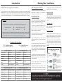
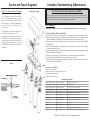
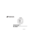
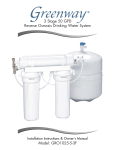
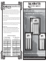
Limited Warranty The Good Water Warehouse Inc. (GWW) warranties the Aquamaster Filtration and Reverse Osmosis system to be free from defects in materials and workmanship under normal use within the operating parameters listed below. For a period of five years from the date of purchase, GWW will repair or replace any part of the Filtration and Reverse Osmosis System with the exception of the filters, membrane and battery. The RO membrane carries a one-year warranty. Filtration & Reverse Osmosis Systems Installation and Service Guide Conditions of Warranty The above warranty shall not apply to any part of the Filtration and Reverse Osmosis System that is damaged due to neglect, misuse, alteration, accident, misapplication, physical damage, fouling, and/ or scaling of the membrane (by minerals, bacterial attack and/or sediment), fire, frozen water, hot water, or an Act of God. The Good Water Warehouse assumes no warranty liability in connection with this Filtration or Reverse Osmosis System other than as specified herein. GWW shall not be liable for consequential damages of any kind or nature due to the use of Good Water Warehouse products. Warranty Service Warranty service will be provided by GWW under the following conditions: 1) Contact your local dealer who will obtain return authorization instructions from GWW. 2) Ship the unit or part freight prepaid to The Good Water Warehouse for warranty evaluation or service. Unit must be returned in the original carton or packaged to prevent possible damage. Systems or parts covered under the warranty shall be repaired (or, at our option, replaced) and returned without charge. CONDITIONS FOR OPERATION TFC - Thin Film Composite CTA - Cellulose Tri-Acetate (in Models AMR4000 & AMR4000P) (in Model AMR3000) Source Water Supply - TFC Source Water Supply - CTA Community/Private Non-Chlorinated Community/Private Chlorinated System Pressure 30-100 psi System Pressure 30-100 psi Temperature 4O-38O C (40O-100O F) Temperature 4O-32O C (40O-90O F) pH Range 3.0-11.0 pH Range 4.0-8.0 Maximum Supply TDS Level 2000 mg/L Maximum Supply TDS Level 1500 mg/L Turbidity <1.0 Net Turbidity (NTU) Turbidity <1.0 Net Turbidity (NTU) Chemical Parameters - T FC Hardness (CaCO 3) Chemical Parameters - CTA <350 mg/L (<20 gpg) Hardness (CaCO 3) <350 mg/L (<20 gpg) Iron (Fe) <0.1 mg/L Iron (Fe) <0.1 mg/L Manganese (M n) <0.05 mg/L Manganese (M n) <0.05 mg/L Hydrogen Sulfide (H2S) 0.00 mg/L Hydrogen Sulfide (H2S) 0.00 mg/L Chlorine (Cl2 ) 0.00 mg/L Chlorine (Cl2 ) 0.1-10.0 mg/L Models AMF2000, AMR3000, AMR4000 & AMR4000P PLEASE READ THIS MANUAL CAREFULLY BEFORE INSTALLATION. INSTALLATION AND SERVICE Introduction 1 Starting Your Installation and light pressure until the porcelain has been penetrated to the material underneath. Please read this entire service guide prior to installation. STEP 1: Drilling the Faucet Hole These Filtration and Reverse Osmosis Drinking Water Systems have been designed for quick and simple installation and maintenance. To insure a successful installation and reliable operation carefully read this instruction manual and following the operational guidelines. Routine maintenance is essential to the longevity and performance of the system. Filters should be changed every six to twelve months depending on the quality of the feed water supply. The product water faucet may be installed on any flat surface at least 2” in diameter. Check the underside of the location for interference. Porcelain/Enamel Sinks A 3/8” variable speed drill is recommended for this procedure. A spring loaded Relton style drill set is strongly recommended to prevent chipping. Preparation Check the following list of components to ensure that all parts are packed with your system: 1 - Filtration or RO System 1 - Faucet 1 - Storage Tank (RO System only) 1 - Installation Kit Determine the location for the installation of the Filtration and RO system, including system, faucet, and storage tank. Avoid locations where the system might come in contact with hot water pipes or other hazards. Inspect the location for the faucet hole to prevent damaging any underlying pipes or wires. TFC - Thin Film Composite CTA - Cellulose Tri-Acetate (in Models AMR4000 & AMR 4000P) (in Model AMR3000) Source Water Supply - TFC Source Water Supply - CTA Community/Private Non-Chlorinated Community/Private Chlorinated System Pressure 30-100 psi System Pressure 30-100 psi Temperature 4O-38O C (40O-100O F) Temperature 4O-32O C (40O-90O F) pH Range 3.0-11.0 pH Range 4.0-8.0 Maximum Supply TDS Level 2000 mg/L Maximum Supply TDS Level 1500 mg/L Turbidity <1.0 Net Turbidity (NTU) Turbidity <1.0 Net Turbidity (NTU) Chemical Parameters - T FC Chemical Parameters - CTA Hardness (CaCO 3) <350 mg/L (<20 gpg) Hardness (CaCO 3) <350 mg/L (<20 gpg) Iron (Fe) <0.1 mg/L Iron (Fe) <0.1 mg/L M anganese (M n) <0.05 mg/L M anganese (M n) <0.05 mg/L Hydrogen Sulfide (H2S) 0.00 mg/L Hydrogen Sulfide (H2S) 0.00 mg/L Chlorine (Cl2) 0.00 mg/L Chlorine (Cl2) 0.1-10.0 mg/L Stainless Steel Sink Make a small indent to mark the desired drilling location using a center punch. Drill a pilot hole with a 1/8” metal drill bit. Enlarge the hole using a 1” metal drill bit. Tile Counter Top The plastic sleeve supplied on the pilot drill is to be positioned on the drill bit against the drill chuck. This prevents the chuck from contacting the porcelain after the pilot hole has been completed. Follow the procedures outlined in the Porcelain/ Enamel Sinks section. Avoid high motor RPM during the initial cutting of the porcelain as this can cause chipping. Once the hole has been drilled in the sink, the faucet may be located in the hole. Be sure the faucet body, faucet base, and the rubber faucet base washer are in place above the sink (See illustration on page 5). Install the star lock washer and nut, then tighten firmly while aligned faucet in the desired direction. Once the faucet is installed, screw the connector fitting provided onto the bottom of the faucet stem and tighten. Using a carbide tipped drill bit, drill a pilot hole completely through the porcelain and the material underneath. Conditions For Operation 2 Place the spring loaded porcelain saw into the drill chuck. Make sure the pilot guide is inserted tightly. Insert the pilot guide into the pilot hole. Push down gently on the drill motor to apply light pressure to the porcelain surface. Start the drill motor turning as slowly as possible. After the initial cut has started, motor speed may be gradually increased. The cut may require three to four minutes to complete. Going faster could result in excessive chipping. Be sure a complete ring has been cut through the porcelain to the material underneath. Place the finish hole saw into the drill chuck. Make sure the pilot guide is inserted tightly. Insert the pilot guide into the pilot hole. Begin cut using a slow speed Faucet Installation 12345678901234567890123456789012123456 12345678901234567890123456789012123456 12345678901234567890123456789012123456 12345678901234567890123456789012123456 Drilling with the recommended 12345678901234567890123456789012123456 12345678901234567890123456789012123456 12345678901234567890123456789012123456 Relton cutter 12345678901234567890123456789012123456 12345678901234567890123456789012123456 12345678901234567890123456789012123456 12345678901234567890123456789012123456 12345678901234567890123456789012123456 12345678901234567890123456789012123456 12345678901234567890123456789012123456 12345678901234567890123456789012123456 12345678901234567890123456789012123456 12345678901234567890123456789012123456 12345678901234567890123456789012123456 12345678901234567890123456789012123456 12345678901234567890123456789012123456 12345678901234567890123456789012123456 12345678901234567890123456789012123456 12345678901234567890123456789012123456 12345678901234567890123456789012123456 12345678901234567890123456789012123456 12345678901234567890123456789012123456 12345678901234567890123456789012123456 12345678901234567890123456789012123456 12345678901234567890123456789012123456 CAUTION DO NOT USE THIS SYSTEM WHERE THE WATER IS MICROBIOLOGICALLY UNSAFE OR OF UNKNOWN QUALITY. THIS SYSTEM IS FOR USE ON POTABLE WATER ONLY. SOURCE WATER EXCEEDING CHEMICAL PARAMETERS REQUIRES PRETREATMENT. 3 Mounting the Filters & Membrane Tapping into the Cold Water Line STEP 2: Shut Off the Water Locate the water shut-off valve for the cold water feed line that you have chosen to use for the supply. Accidentally hooking up the system to the hot supply line will permanently damage the membrane (See Conditions for operation). To assure you are using the cold water line turn on both the hot and cold faucets. After the water is warm, feel the pipes underneath the sink to identify the hot and cold. Close the cold water valve. Turn on the cold water faucet only to assure that the line is completely shut off and the line is drained. If no shut off valve is located under the sink, turn off the main supply at the entry to the house. Place the clamp over the cold water supply line. The aluminum spacer has two sides to adapt to different tubing sizes. Use the small radius for 3/8” tubing and the large radius for tubing through 5/8”. Use the clamp screw to attach the saddle to the copper pipe. Tighten the brass clamp screw with a 7/16” wrench. STEP 3: Mounting the Tank Ball Valve STEP 5: Mounting the Filters & Membrane Screw the filters onto the mounting head starting from left to right in the order listed below, matching the filter label to the respective position labeled on the mounting head. Note: Do not tamper with the air valve on the storage tank. It has been preset and screwed on with blue cap by the manufacturers. (1) Wrap the threads on the top of the water storage tank 3 times with plumbers (Teflon) tape only. Make sure it is tight, but not over tight. (2) Connect the tank ball valve assembly to the top of the water storage tank. (3) Connect the tube from the RO module to the water storage tank. Important: Remove the black protective cap from the membrane before screwing in place. Model PreFilter AMF2000 Q5605 AMR3000 Q5633 AMR4000 Q5605 AMR4000PQ5605 4 Fittings and Tubing John Guest™ fittings are used throughout the system. To insure an optimal seal, tubing should be cut with the end square. An angled cut or distortion of the tubing will not provide an efficient seal and may cause leaks. To install a tube, push it through the collet until it seats firmly. To remove a tube, push in the collet and pull out the tube. Carbon Membrane PostFilter n/a n/a Q5615 CQ56-18TC Q5633 n/a Q5633 TQ56-35TC Q5633 Q5633 TQ56-35TC Q5633 STEP 4: Installing the Drain Clamp (RO System only) Select a location for the drain hole based on the design of the plumbing. Position the drain outlet saddle on the drainpipe. Allow adequate space for drilling. Tighten the bolts evenly on both sides. Avoid over tightening. Using the opening in the drain outlet saddle as a guide, drill a 1/4” hole in the drainpipe. Clean debris from the saddle and threads. Do not over tighten the clamp. The clamp should be secure and resist a slight twisting force. Turn the saddletapping valve clockwise until the needle fully pierces the tubing and the valve seats. For maximum flow, back the handle out all the way. Adjust as required. Check for Leaks STEP 6: Tubing Connection For RO Systems, determine the location for the storage tank. A maximum distance from tank to faucet is 15 feet. The fastest flow at the faucet can be achieved by minimizing the length of the tubing from tank to faucet. STEP 7: Activating System for the First Time For ease of installation all tubing is individually labeled and color coded (AMR3000, AMR4000, & AMR4000P). Slowly turn the saddle valve counterclockwise until fully open. Check stem seal for leakage. If necessary tighten stem nut lightly. 1/4” Red - Connects the feed water valve to the pre-filter. 3/8” Blue - Connects the RO membrane product port to the Turn storage tank valve one quarter turn counterclockwise to open the valve (the handle should be in line with the tubing as it enters the connection). storage tank. 1/4” Black - Connects the membrane brine port to the drain Turn on the cold water supply. Check the saddle-tapping valve for leaks. Allow the water to run for a minute to clear any possible debris from the saddle-tapping device. If flow from the faucet is reduced, remove, clean, and reinstall the faucet aerator. Make sure all water supply/drain lines are secure and free from leakage. connector. NOTE: Some states and provinces require the use of an air gap faucet. To assure compliance check your local plumbing code. Locate the drain connection away from the garbage disposal to prevent potential contamination and system fouling. 3/8” White - Connects the postfilter to the faucet. Note: AMF2000 only requires 3/8” Blue & 3/8” White Open the product water faucet and let the water flow until all the air has been expelled from the system. This will take about an hour for an RO system. Close the product water faucet. In 30 minutes, check the connections for leaks and correct if necessary. 5 System and Faucet Diagrams STEP 8: Ice Maker Hook-Up (Optional) If your refrigerator is less than 25feet to your RO unit, 1/4” polypropylene plastic tubing is recommended. If your refrigerator is greater than 25 feet from your RO unit, 3/8” tubing is recommended. Do not use copper tubing as an objectionable ice cube taste can result. To begin, install a tee in the white tubing between the final filter and the faucet. Next, it is recommended to install a ball valve in the line to the ice maker. This will allow storage tank pressure to increase suffieiently for the ice maker solenoid to operate properly. Leave the ball valve in the closed position until the tank is full after start up procedure is completed. Activation, Troubleshooting, & Maintenance 6 Do Not Use the First Two Reservoirs of Water. Aquamaster System Allow the reservoir to fill for 4-6 hours. Dispense this water to drain. This process removes the factory installed sanitizing solution from the entire system and sends it to the drain. Repeat this process one more time. Allow the tank to fill for 4-6 hours and dispense this water to the drain. Filter Maintenance Filters should be changed every six to twelve months depending on the quality of the feed water supply. RO System (AMR3000, AMR4000, and AMR4000P) 1) Open the RO faucet and let the tank drain completely. Leave the faucet open until the filter change is complete. 2) Remove the pre-sediment cartridge - Simply turn the pre-filter cartridge counterclockwise and remove it (Models AMR3000, AMR4000, and AMR4000P). This will automatically shut off the water supply at the RO. 3) Remove the pre-carbon cartridge - Simply turn the pre-filter counterclockwise and remove it (Models AMR4000, and AMR4000P). 4) Remove the membrane cartridge - The membrane may be reused indefinitely as long as the TDS level and other troubleshooting guidelines are met. 4) Remove the post-carbon cartridge - Simply turn the post-carbon cartridge counter-clockwise and remove it (Models AMR3000, AMR4000, and AMR4000P). 5) Install the new filters in the opposite order from removal. Note: AMR3000 has no pre-carbon cartridge. 6) Install the new pre-filter cartridge last. This will automatically turn on the system. 7) Drain the first tank of water after changing the filters before drinking. When the membrane is changed, drain the first two tanks of water before drinking. Faucet Filtration System (AMF2000) 1) Shut off the water supply. 2) Remove the cartriges by turning counterclockwise. 3) Install the new filter cartridge. 4) Turn the water supply back on. Troubleshooting Guide Water has an offensive taste and/or odor Carbon post filter is depleted Drain storage tank and replace post filter Water has an offensive taste and/or odor Sediment/Carbon filters are depleted Replace filters, clean system Water has an offensive taste and/or odor Membrane depleted or fouled If monitor indicates red light, drain storage tank, system. replace Drain storage tank, replace membrane, & sanitize Not enough product water pressure Storage tank air pressure charge is low Empty storage tank and set pressure to 8 psi (55 kPa) Not enough water Low water pressure If line pressure is below 30 psi add a booster pump Not enough water Water supply is blocked Clear restriction, rotate valve on feed water valve Not enough water Storage tank is depleted Consider an increase in tank or membrane capacity Not enough water Clogged pre-filter cartridge Replace prefilter, drain tank and sanitize system No drain water Clogged flow restrictor Replace membrane No water Water supply is turned off Turn water on Under sink is wet Leak from valve, faucet or fitting Dry everything with towels to isolate leak, identify, and fix Red service light Depleted membrane or low usage Run faucet for 10 seconds and check again, if persists, change membrane Questions? 1-877-661-0425 or visit www.aquamaster.ca membrane, sanitize system