1
.. ....J
..
HF-125
Gene~al
Coverage Receiver.
User Manual.
Contents.
Introduction . . . . . .
Getting star ted . . . . .
Controls and Connections
Operating the HF-125
Care of your Receiver . .
General notes . . . . . .
Optional Units for the HF-125
Circuit description
Circuit diagrams
Specification
HE' Band plan
2
3
9
11
16
16
17
18
20
23
24
(c) 1986 Lowe Electronics Ltd.
Bentley Bridge,
Chesterfield Road,
Matlock, Derbyshire.
Printed in England.
MOl-1250
Page 1
HF-125 User manual.
Introduction.
The term "Conununications Receiver" was originally used in its 'guite
literal sense to describe a radio receiver which was part of a point to point
conununications link.
These radio links were normally manned by trained operators, and Morse
Code was the usual method of transmitting information. Because of the
special ist nature of the system, and the fact that the operators were
technically trained, the commuoications receiver itself was quite often a
complex piece of eguipment.
Over the past twenty or so years, a marked change has taken place in HF
spectrum occupancy, and there has been a considerable increase in the use of
short wave broadcasting, air traffic control, news agency transmissions and so
on. The interest in listening generated by this spread of activity has lead to
a demand amongst the general public for receivers which will enable them to
keep in touch with world affairs by short wave radio.
Clearly, these users of receivers are relatively unskilled in the
handling of complicated equipment and this in turn has resulted in the
introduction of simpler receivers. However, simplicity of operation has often
been accomplished by a compromise in actual performance, and the results
obtained from some of these simple receivers have been guite disappointing.
As our Chairman once remarked, "Some receivers are rat her like a
chocolate eclair; Wonderful to behold but containing little of substance."
The design and development of the HF-125 was based on straightforward
objectives;
1) To obtain sufficient RF performance for the receiver to
operate without problem in crowded bands with many
strong signals.
2) To combine complete control of a necessarily complex
piece of equipment with easy operation for the user.
]) To achieve both the previous objectives within a
reasonable price range.
We believe that these stated goals have been reached, and that the HF-125
receiver represents a truly new approach to meeting the demands of the
educated short wave listener.
Page 2
HF-125 User manual.
Getting started.
Aerials and Earths.
Operating the HF-125 is described i~ the next two sections of this
manual, but you may weIl ask "What is a suitable aerial?" The receiver has
been designed to work weIl with a simple long wire aerial of about 10 to 30
meters in length. This will provide good results on most frequencies covered
by the receiver, but if your interest is in a particular band, such as the 49
metre broadcast band, you may wish to consider a dipole aerial tuned to that
frequency. As an extension to the dipole idea, you could make use of a "Fan"
or multi-band dipole. Details of these aerials are given below, together with
formulae for working out their lengths.
00 not be dazzled by the idea of putting up the longest wire in the whole
world. This will bring you to grief, because you will probably overload the
input stages of the receiver with signals from strong broadcast transmitters,
with resultant problems of cross modulation and intermodulation.
Adecent RF ground system is always an advantage, and this can be made
fairly simply by driving a metal post into the ground to a depth of about 3 to
4 feet. Whilst a single ground spike is acceptable, better results will be
obtained by using more than one spike, all joined together by heavy copper
wire above ground, and taken to the ground connection on the re ar panel of the
receiver. The mains ground is an alternative, but whilst it is good enough for
safety purposes it often carries quite high levels of electrical noise.
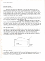
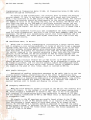
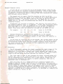
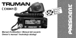
The Long Wire Aerial.
This is the simplest type of aerial system, and consists of a singlewire
erected with a horizontal top section and a down lead from one end going to
the receiver's 600 ohm aerial input terminal. The wire should be erected as
high as possible, and as far as possible away from other structures or
overhead power lines. Insulators should be used as shown, and the lead in wire
should also be insulated. The drawing shows a long wire in the form of an
"Inverted LU, but many other configurations can be used, such as a slanting
wire leading directly to the receiver.
/ E 9 9 Ins.lotar. ~
Lang Wir.
L
10 m to 30 m
LI
-0
To Receiver
Graund
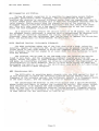
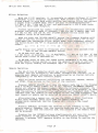
The Dipole Aerial.
This is normally constructed for a specific frequency or band of
frequencies, and the length of the aerial is therefore critical. The length in
met.res is given by dividing 143 by the operating frequency, or the centre
frequency of the band (in Megahertz).
Page 3
HF-125 User manual.
Getting Started.
Remember that the dipole has directional properties, with maximum
received signal at right-angles to the aerial and minimum signal along its
length. It presents a low impedance at the centre feed point, and is best
connected to the receiver by co-axial cable. At HF either 50 ohm or 75 ohm
cable is satisfactory. The purist will point out that the dipole is a balanced
device and the co-axial cable is unbalanced. A balanced to unbalanced
transformer (Balun) may be used at the centre point to correct this, but for
the general listener it is not often required. A balun will help to reduce
electrical interference picked up in the down lead to the receiver.
E99 Ins\o+:
~
L
E_99.. . ' Totor
"w.~'"~'_.~
OU1.. :.-a,d
c.... tt'<"QO'lIio>c""
Dipole
143
Umetros) = Freq (MHz)
~_ _+-Co-oxlol
T0
Coble
Rocolver
The "Inverted V" aerial is a variant of the dipole in which the ends are
dropped to terminate at points closer to the ground, and a single central
support is used. It is very convenient when suitable dipole supports are not
available. The effect of the ground modifies the length formula, and 148
should be substituted in place of 143.
The Fan Dipole Aerial.
The fan dipole is aseries of dipole elements connected to a single
feeder at a common central point. Clearly there is a limit to the number of
elements which can'be accommodated, and this is normally three or four. There
is some interaction between the dipoles, but the basic formula should be used
for calculating the length of each element.
Egg In.\o.-:
Eoch Dipole
Umetre.) =
L
143
Freq (MHz)
E_9g.....l.ln,.ulotor
~_ _-+-Co-oxiol
Coble
To Receiver
The vertical Aerial.
There are several ready-made vertical aerial systems on the market, and
they will provide an easy to erect system occupying very little ground area.
These aerials are normally designed to work over quite a narrow"frequency
range (typically amateur radio bands), and for general listening a simple wire
will give better results.
Page 4
HF-l25 User manual.
Getting Started.
The Power Supply and other Connections.
The HF-l25 requires an external DC supply of between 10 and 15 volts. The
absolute maximum supply is 16 volts, and if this is exceeded damage may occur
to the receiver. The supply polarity is negative· ground only, and although
reverse polarity protection is built in it is wise to ensure that any supply
is correctly connected. Be sure that the receiver power 5witch is OFF be fore
plugging in or unplugging the power connector.
In most countrie5, the HF-125 will be supplied with a small 12 volt
regulated power unit which is designed to operate from the local mains power.
Remember that this 5upply will be operating all the time that it i5 connected
to the mains outlet, and it i5 a wise safety precaution to disconnect It when
the receiver is not in use.
In the uni ted Kingdom the power supply is fitted with a three-core mains
lead, and the earth connection (yellow/green) is connected to the negative
(groundl terminal of the receiver. This provides a reasonable earth connection
for the receiver, but in some cases, where mains-born interference is
prominent, it will be neces5ary to provide the receiver with a good RF earth,
either in addition to the mains earth or in some cases instead of it. If the
receiver is used with any other mains power supply it should be able to comply
with BSI standards relating to Class 2 insulation.
External Loudspeaker.
A small internal loudspeaker is provided in the HF-125 so that it i5 self
contained, but although it can provide reasonable all round audio quality,
clearly in the limited space available compromise has to be made. You will
find that if the volume control is set to a high level there may be some audio
feedback caused by vibration induced by the internal loudspeaker. If it is
necessary to operate the receiver for long periods at high audio levels the
use of an external loudspeaker is recommended.
Because the HF-125 is capable of giving a high quality audio signal, we
suggest you use a good external loudspeaker, and a small bookshelf type Hi-Fi
unit is satisfactory. We can provide a suitable unit as an optional accessory
with the correct connecting lead for the HF-125. Any external loudspeaker
should have an impedance of 4 to 8 ohms.
Record Output.
Many keen listeners like to tape record any interesting stations they
hear, and a low level audio output has been provided for this purpose. The
RECORD OUT socket accepts a 3.5mm mono jack plug and provides a level suitable
for feeding into the "Line" input of most tape recorders or amplifier systems.
An attenuating resistor should be added in the lead if feeding directly into
the "Mic" input of a cassette recorder. The output level at this socket is not
affected by the Volume or Tone controls, so that the loudspeaker can be used
to monitor whilst recording.
The re cord output can also be used for driving most types of receiver
ancillary equipment such as RTTY or Morse Code decoders. The output level is
between 100 and 150 mV from a source impedance of 15 Kahms.
Page 5
HF-125 User manual.
Getting Started.
Types of Signal.
The HF-125 is equipped to receive most types of transmission likely to be
encountered within its tuning range, and although most users will be familiar
with these, here is a short section on this topic that may be useful to the
beginner.
AM (Amplitude Modulation).
This was the earliest method used of audio modulation of an RF carrier
wave, and is still almost universally used for long, medium and short wave
broadcasting. An AM signal is fairly easy to tune in, and given a reasonable
signal strength, the receiver may not need to be "spot on" in frequency.
However when conditions are poor, AM can be difficult to resolve - one
particular problem is frequency selective fading and this is discussed later.
AM Selectivity.
A radio signal occupies a certain portion of the radio spectrum which is
known as its bandwidth. The bandwidth cf an AM signal is twice its highest
modulation frequency, and because of th{s broadcasters are restricted to
transmitting audio frequencies below 5 kHz so that they do not occupy too much
spectrum. In the long and medium wave broadcast bands, station freguencies are
separated by 9 kHz (la kHz in the USA) so there is little or no overlap of
adjacent signal bandwidths. In the short wave bands however, the stations use
a nominal5kHz spacing, and some broadcasters do not abide by any rules at
all, so there is considerable signal overlap.
The HF-125 is provided with four different filter bandwidths because of
this very problem. If you are re~eiving a strong signal in a clear part of the
radio spectrum then you can use the 10 kHz filter and obtain the best
fidelity. The stronger and closer adjacent stations are, the narrower the
filter you will need, and the more muffled the sound will be because high
frequencies are removed. The 7 kHz filter provides a good compromise for most
medium wave conditions, and the 4 kHz filter for short wave. The 2.5 kHz
filter can be used under severe conditions, but it is really only suitable for
speech reproduction.
When AM mode is selected on the HF-125, the 7 kHz filter is initially
switched in. If you want to change to a different filter you can use the
FILTER SELECT function. You may find that reception of astation is improved
by tuning the receiver slightly above or below its carrier freguency. This is
quite a useful technique if there is a strong adjacent signal that you don't
want. As long as the carrier signal is within the receiver's filter then all
will be weIl, but if you tune too far or select a narrower filter then the
signal will become distorted.
SSB (Single Sideband).
An AM signal can be considered as a carrier wave combined with two
identical sidebands which contain the modulating audio signal. It is possible
to remove one of the sidebands without losing any vital information, and
immediately halve the bandwidth occupied by the signal. In practice the
carrier wave is also removed (or partially suppressed) to improve transmission
efficiency, and the result is a single sideband transmission.
SSB transmissions are used extensively for voice communication,
particularly to aircraft and shipping, and also by radio amateurs. It is
possible to use either of the two initial sidebands of a signal, so there are
two distinct types of SSB transmission; Upper Sideband "(USB) where the
sideband frequency is above the carrier frequency, and Lower Sideband (LSB)
where it is below. Nearly all commercial transmissions are USB, as are amateur
Page 6
HF-125 User manual.
Getting Started.
transmissions at frequencies above 10 MHz. At frequencies below 10 MHz radio
amateurs use LSB by convention.
To receive an SSB transmission, the receiver must re-insert the missing
carrier signal. If this is not done the signal will sound just like Donald
Duck, - try listening to an SSB signal in AM mode for this effect. For correct
reception the receiver should be tuned exactly to the carrier frequency, but
for speech an error of 50 Hz either ~ay will not be serious. The HF-125 has a
very slow tune rate on its SSB mode to facilitate accurate tuning, but you
will need a steady hand. The pitch of the received voice will change as you
tune through the signal, but only at one tuning position will it sound like a
natural voice.
A 2.5 kHz bandwidth filter will just accommodate the audio frequencies
used for voice transmission, and this is the filter most commonly used for SSB
reception. The HF-125 will automatically select this filter whenever tSB or
USB modes are chosen, but under good signal conditions the 4 kHz filter may
offer improved clarity.
CW (Continuous Wave, ie Morse).
Morse code is usually transmitted by interrupting a single carrier wave,
and it occupies a very narrow bandwidth. In terms of ability to get a message
through under difficult propagation conditions Morse code is one of the most
efficient methods, although modern error-correcting teleprinter systems are
also very good. CW signals are received in the same way as SSB signals, with
the carrier inserted in the receiver producing a beat note with the incoming
carrier. In the CW mode the HF-125 provides an 800 Hz off set between the
display and the internal carrier, so that a note is heard at 800 Hz when the
receiver is tuned exactly to the signal.
The HF~125 initially selects the 2.5 kHz filter in CW mode and this
sbould be used for finding and tuning signals. As an alternative a narrow 400
Hz filtaE is provided, and its use will greatly reduce the background noise,
allow~ng the Morse to be more easily read. Careful tuning is needed to place
the signal at the peak of this filter, which is centred on 800 Hz.
RTTY (Radio Teletype).
7
The method of sending teleprinter messages by HF radio link is to use two
closely spaced signals, transmitting one or the other to send binary data.
Each teleprinter character is encoded into a different sequence of tones which
are transmitted in a bewildering combination of different speeds, tone shifts,
and codes. RTTY signals are tuned in SSB mode on a receiver, but require a
special terminal unit to decode and display the actual text.
FM (Frequency Modulation).
When the 0-125 detector option is fitted to the HF-125, the receiver will
receive FM signals. In the context of an HF receiver this means narrow band
FM, which occupies a bandwidth of around 12 kHz. This is not to be confused
with broadcast FM transmissions which have bandwidths in excess of 150 kHz,
and are normally transmitted at VHF or UHF where there is sufficient spectrum
to accommodate them.
FM signals in the HF spectrurn are usually found eithe~ in the 27 MHz
Citizens Band or in the 28 MHz amateur band. It is typical of FM receivers
that they produce a large amount of noise when there is no signal at the
aerial. To overcome this a squelch system is employed to turn off the audio
output unless a signal is detected. The HF-l25 squelch system may be turned on
or off manually by using the filter select control. The filter bandwidth i5
fixed at 12 kHz in FM mode.
Page 7
HF-125 User manual.
Getting 5tarted.
AM Propagation and Fading.
During AM signal reception it is possible to experience severe fading
problems, particularly after nightfall. This is mainly due to the signal
reaching the receiver by several different paths from the transmitter, and it
is most common after dark because this is when the ionosphere reflects most HF
radio signals. Fading occurs when the signals arrive at the receiver in
antiphase (having travelled different distancesl and then cancel each other
out. This will only occur at a few specific frequencies at any one instant,
hence the term frequency selective fading.
If a selective fade reduces the carrier level of an AM signal, but leaves
the sideband levels unaltered, a receiver with a conventional AM detector will
not be able to correctly reproduce the signal, and the output will be
distorted. There are two techniques that can be used to improve the situation;
ECSS, and Synchronous (or Phase-LockedJ AM detection.
ECSS (Exalted Carrier, Selectable 5idebandJ.
The ECSS technique makes use of the fact that with a good, selective
receiver, capable of resolving SSB, an AM signal can be passed through the 5SB
filter which is only wide enough to allow one sideband through. The filter
must attenuate the carrier signal by at least 20dB for this technique to work
with any success.
The receiver can be used in the SSB mode with the incoming AM carrier
tuned to zero beat, and the accompanying sideband treated as a true 5SB
signal. Either the upper or lower sideband can be selected using either USB or
LSB mode, so interfering stations can often be eliminated. The improvement in
intelligibility is often dramatic, and it is weIl worth trying out ECSS and
developing the ability to use it. The HF-l25 when used with its 2.5 kHz filter
is ideally suited to ECSS reception.
AMS (Synchronous AMJ.
The difficulty in receiving music signals with the ECSS method is that it
is very difficult to match the receivers injected carrier exactly with the
frequency of the incoming carrier. Any difference results in a frequency shift
of the audio signal, and the consequent 1055 of harmonie relationships.
The synchronous AM detector in the D-125 option uses a narrow deviation
phase-locked oscillator to replace the incoming AM carrier. When phase locked,
this oscill.ator is at exactly the same frequency as the carrier signal, and
does not have to relY'on absolute receiver tuning accuracy. Incoming carrier
level changes make no difference to the signal detection provided that there
is some carrier for the oscillator to lock on to.
Page 8
HF-125 User manual.
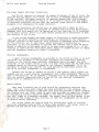
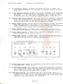
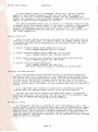
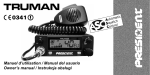
Controls and Connections.
cp
2
I
HF-12
\
~
(1)
Signal strength meter: Calibrated SI to S9 and 10dB, 30dB and 50dB above
S9. The S9 signal strength is calibrated at 50 microvolts p.d. at the
50 ohm antenna socket.
(2)
Mode switch: Selects one of six available reception modes:
CW
LSB
USB
AM
AMS
FM
For
For
For
For
For
reception of CW (Morsel signals.
single-sideband signals, (Lower sideband).
single-sideband signals, (Upper sidebandl.
reception of AM (broadcastl signals.
AM reception using the synchronous detector.
(0-125 option).
For reception of narrow-band FM signals. (D-125 option).
(3)
Memory mode flag: 1s illuminated when the frequency display is showing
memory information.
(4)
Frequency display: A 5-digit back-lit LCD showing the received frequency
to the nearest kilohertz. Frequencies below 1600 kilohertz are shown
directly and those above in megahertz, with a decimal point separating
MHz and kHz.
(5)
Main tuning knob: For tuning the receiver in all modes. The rate of
tuning is selected according to the receiver's mode and the speed of
rotation of the tuning knob.
(6)
Headphone socket: A headphone output jack for a standard 1/4" plug. Mono
or stereo headphones may be used (stereo phones operating in mono),
and the internal loudspeaker is disconnected when the headphones are
connected.
(7)
Volume control and Power switch: Controls the volume" in the loudspeaker
and at the headphone output. When turned fully counter-clockwise to
the click position, the receiver power is turned off, and if the
internal rechargeable batteries are fitted (P-125 option) then these
are switched into charge mode.
(8)
Tone control: Varies the audio tonal quality in the loudspeaker and at
----the headphone output. The control provides either high frequency cut
or low frequency cut, with a flat response in its central position.
page 9
Controls and Connections.
HF-125 User manual.
(9)
R F Attenuator control: Displays, and allows the user to change, the
-state of the- attenuator. A fixed 20dB of attenuation may be switched
in or out.
(10) Filter selection control: Enables the receiver bandwidth to be displayed
and changed. In LSB, USB, AM and AMS modes, four different filters are
available:- 2.5, 4, 7 and 10kHz. In CW mode, two:- 2.5kHz and 400Hz.
In FM mode this. control turns the squelch facility on and off.
(11) Me9ahertz fast tuning buttons: Tunes the receiver in megahertz increments
up or down the HF spectrum. The tuning will continue automatically if
either of the buttons is held pressed, but will stop when the upper or
lower frequency limit of the receiver would be exceeded.
(12) Memory SELECT control: Firstly switches the frequency display into memory
mode, and then selects each memory in turn. Sequential selection
occurs automatically if the button is held pressed, and memory mode is
retained for three seconds after the button is released.
(13) Memory RESTORE control: In memory mode, returns the receiver to its
original tuned frequency, effectively cancelling any memory RECALLs.
(14) Memory RECALL control: In memory mode, transfers a frequency from the
selected memory to the receiver tuning.
(15) Memory STORE control: In memory mode, transfers the cUrrent receiver
frequency into the selected memory, over-writing any previous content.
Both STORE buttons must be pressed simultaneously.
HF-125
HF COII'II"u,rl\lcotlot\$
h'
®
\
I
K~D
I
NO
Lo',14 EI.e~rol\l" Lt.d
~
I
I 5&..101
'hcIIV4r'
......... Mlr~ttuud In Er-glot\4
®
;'
\
;~
@
Q(
ANTENNA
,I
I
i
GRG UNO
el~ ~10
WhIp
\f
I
I
600JlJ""RE
~
20
I
FM SQl/ELCH
LEr
i.~
o
(16)
I
I
I
~
LS
,
~
@
I
T
@
I
l
f 2VOe
cb
I
R~mote
keypad jack socket: For connection of the Genie keypad for direct
frequency entry. (K-125 option)
(17) 50 ohm antenna socket: For connection of antennae terminated with 50 ohm
or 75 ohm co-axial cable. The cable should be fitted with a PL-259
plug to match this socket. Also used for mounting the telescopic whip
aerial when the P-125 portable option is used.
(18) Whip antenna switch: Only present when the P-125 portable. option is
fitted, this changes the 50 ohm antenna socket into an active antenna
connection for a whip aerial. The switch should be in the normal (up)
position if any other aerials are connected.
Page 10
HF-125 User manual.
Controls and Connections.
(19) 600 ohm antenna terminal: For connection of wire antennae not terminated
--withco-axial cable.
(20) Ground terminal: Connected to the case of the receiver. A good earth
connection will improve reception and reduce interference,
particularly with a wire aerial.
(21) FM sguelch level adjustment: Only present when the D-125 detector option
is fitted, this screwdriver adjustment sets the signal level at which
the squelch circuit turns on the audio output.
(22) Record output jack socket: A fixed level signal is available here that is
unaffected by the volume or tone control settings. The level is
suitable for feeding into the line-input of most tape recorders, and
for driving RTTY decoders.
(23) External loudspeaker jack socket: For connection of an external
loudspeaker of 4 or 8 ohms impedance. Insertion of a plug into this
socket will cut off the internal loudspeaker.
(24) 12V DC power input socket: For connection of a suitable power source.
Ensure correct supply polarity (as marked on the panel) and that the
voltage does not exceed 15V.
Operating the HF-125.
Volume and Tone Controls.
The volume and tone controls affect the level and quality of the sound
from the loudspeaker or fed to the headphones. The signal from the RE CORD
OUT socket on the rear of the receiver is not altered by these controls.
The tone control can provide quite comprehensive audio filtering
facilities. When in its central position the response is flat, but when
turned to the left high frequencies are reduced and this can be used to
lessen the unpleasant whistles from interfering stations. when turned to
the right low frequencies are reduced and the clarity of speech is often
improved.
The volume control also functions as apower switch, and turning it
fully counter-clockwise will turn the receiver off. If you are running
the receiver from its mains adapter then the adapter will still be
running even if the receiver is turned off, and you should switch off or
unp lug the adapter when not in use.
If internal rechargeable batteries are fitted to the HF-125 (the P-125
portable option) then the batteries will charge if power is supplied to
the receiver when it is switched off. The batteries will fully charge in
about 20 hours from a completely discharged condition. A limited amount
of over-charging will not harm the batteries, but you should avoid
charging for periods longer than 48 hours. when the receiver is switched
on a small trickle-charge is supplied to the batteries which will
maintain a full charge against gradual leakage.
Page 11
HF-125 User manual.
Operation.
Receiver Tuning.
The HF-125 is tuned with a single rotary control <whieh drives a
digital shaft encoder) giving continuous tuning over the whole of the
receiver's range. There are no separate tuning bands on the HF-125, but
for convenience two buttons, [MHz DOWN] and [MHz UP], are provided to
tune in one-megahertz steps to a frequency near to the one of interest.
The frequency readout on the HF-125 is at the true carrier frequency
in all modes of reception. It is at the centre of the filter passband in
AM mode, and at the re-injected carrier frequency in USB and LSB modes.
An 800 Hz offset from carrier is provided in CW mode. Although the
frequency display changes in 1 kilohertz steps the receiver is aetually
tuned in much smaller steps. These are suffieiently small for tuning to
appear to be continuous.
The rate at which the receiver tunes when the tuning knob is rotated
depends on the mode selected and on the speed of rotation of the knob.
All modes, with the exception of AMS, offer the faeility of speed-up
tuning - when the tuning knob is rotated rapidly the tuning rate
increases. This allows a slow tuning rate for precise signal resolution
coupled with the ability to reach the required frequency quickly.
You may find at first that the receiver apparently "jumps" in
frequency when you are trying to tune a signal. This is because you have
moved the tuning control quiekly or in a jerky fashion and the receiver
has increased its tuning rate. A smooth action will eure the problem, and
will make tuning the HF-125, and any other receiver, much easier.
The tuning rates adopted by the HF-125 are shown in the table below:
Receiver Mode
Normal tune rate
Tuning step
kHz per rev
I
Fast tune rate
Tuning step
kHz per rev
------------- ------------- ------------- -----------LSB, USB & CW
AM
FM
AMS
15.6 Hz
62 Hz
125 Hz
15.6 Hz
3.125
12.5
25
3.125
250 Hz
50
500 Hz
100
500 Hz
100
Only normal rate
When the operating frequency limits of the HF-125 are reached, tuning
will stop. There are no mechanical stops on the tuning knob, but you will
notice that the frequency display stops changing. The lower tuning limit
is 30 kHz and the upper limit 29.999 MHz on a standard model, but these
are changed to 150 kHz and 26.1 MHz for the German market. Unlike some
receivers, the HF-125 does not "wrap-around" between its highest and
lowest frequencies.
Tuning in AMS mode.
In AMS mode (only with the D-125 detector option fitted) the tuning
control is used in a slightly different way. The synchronous AM detector
is not suited to search tuning - ie tuning the bands to find stations
so this should be done with the receiver set in the normal AM mode. When
astation has been tuned, the AMS mode can be selected, and the tuning
control used to fine-tune the receiver until the deteetor locks to the
signal. The receiver will only tune 4kHz in either direction when in AMS
mode.
When AMS mode is selected it is likely that you will hear the signal
with a superimposed tone. Slowly turn the tuning knob so that the pitch
of the tone falls, and continue until the tone stops. Finally tune for
the best clarity of reception. During severe carrier fading it is
possible for the detector to unlock from the signal, causing a "tearing"
sound. This effect can often be minimised by some judicious fine tuning.
Page 12
Operation.
HF-125 User manual.
Keypad frequency entry.
If your HF-l25 is fitted with the K-l25 keypad option, then you can
tune the receiver by entering frequencies directly. This is very useful
for quickly checking stations at known frequencies, or for setting the
frequency in a particular band of interest and then searching for signals
with the main tuning control.
The keypad unit is remote from the receiver so that is can be
positioned in a convenient place. It is connected by a short eable whieh
should be plugged into the KEYPAD jaek on the rear of the HF-125. The
keypad has 12 keys - the digits [0] to [9], the ENTER key [#], and a
CANCEL key [*]. As keys are pressed they are shown on the reeeiver's
frequeney display.
~
J
Frequencies are entered in kilohertz. The receiver will only tune to
the entered frequency when it is eomplete - either when sufficient digits
have been keyed in or when the ENTER key [#] is pressed. Frequencies
above 3000 kHz will enter automatieally as so on as the last digit is
keyed. Those below 3000 kHz should be followed by the ENTER key [#].
FOr example;
[1]
[5 ]
[0 ]
[7]
[2 ]
f 0]
[0]
[# ]
[0 )
tunes to 15.070 MHz
tunes to 200 kHz
Beeause frequencies entered by the keypad are to the nearest
kilohertz, it may be neeessary to re-tune the receiver slightly to
eorrectly resolve single sideband signals or when using the receiver in
AMS mode.
If you press an incorrect key on the keypad, the current digits can be
cleared by pressing the CANCEL key [*], after wh ich the frequency should
be re-entered. Please note that onee keypad frequency entry is started
the other eontrols on the receiver will be inoperative until entry is
completed or cancelled.
R F Attenuator.
The RF attenuator reduees the signal reaching the input stages of the
receiver from the aerial. There are two situations where its use is
benefieial, firstly when a strong local signal exeeeds the range of the
automatie gain eontrol in the receiver, and secondly when strong signals
close to the one being reeeived overload the reeeiver's input.
The first ease is easy to see, beeause the signal strength meter will
deflect weIl over to the right-hand end of its seale. The seeond effect
ean be recognised with experience, but is more subtle. Either way, if
switching the attenuator on results in better reception, then use it.
Otherwise leave it switehed off.
When you press the [R F ATTEN] button the frequeney display will
change to show the present eondition of the attenuator. There are two
possible meg,sages, either "OFF" or "ATTN". If the button is pressed' again
whilst either of these show, then the attenuator state will be ehanged,
and the display changed aecordingly. The display will revert to the
reeeiver's frequency after about 3 seconds. The attenuator in the HF-125
applies a fixed 20 dB of attenuation when it is switched in, redueing the
signal voltage by a faetor of ten.
Page 13
HF-125 User manual.
Operation.
Filter Selection.
With the HF-125 receiver, it is possible to select different IF filter
bandwidths to suit reception conditions. Wide filters can be used with
strong signals to give good audio quality, and narrow filters can extract
a signal from a crowded band. There are four IF bandwidths offered:
2.5 kHz, 4 kHz, 7 kHz and 10 kHz, and additionally a 400 Hz wide audio
filter for Morse Code reception.
Filters appropriate for normal conditions are automatically selected
whenever the receiver mode is changed; 7 kHz for AM, 4 kHz for AMS, and
2.5 kHz for USB, LSB and CW. The [FILTER SELECT]· button allows the
automatie choice to be overidden.
When you press the [FILTER SELECT] button the frequency display will
change to show the current filter bandwidth (in kHz) and an "F" on the
right-band side indicating filter select mode. Each subsequent press of
the button whilst the "F" is displayed will select a new filter in the
order:
2.5 ---) 4 ---) 7 ---) 10 ---) 2.5
etc
The display will revert to frequency after about three seconds from
the last press of the [FILTER SELECT] button.
In CW mode only two filters are available, 2.5 kHz and 0.4 kHz. If the
0.4 kHz filter is selected, the 2.5 kHz filter remains in the IF, and the
narrow audio filter is switched in.
In FM mode there is only one fixed filter bandwidth of 12 kHz. The
[FILTER SELECT] button serves to turn the squelch facility on and off,
with the display showing the messages "SQL" or "OFF" as appropriate.
Memory Operations.
The HF-125 has 30 memories which can store receiver frequency
settings. They are arranged in two banks, standard and alternate, of 15
memories each. Memory information is maintained by an internal battery
independently of the main receiver supply.
There are three functions controlling the memories - SELECT, RECALL
and STORE - from buttons on the front of the receiver:
Pressing [MEMORY SELECT] will show the memory mode flag in the display
with a two-digit memory number (01 to 15). Holding the [MEMORY SEL~CT]
button will advance the memory number. When the button is released, the
frequency stored in the selected memory will show on the display. At this
time the receiver's tuning will be unaffected, and the memory mode flag
indicates that the reading on the display is not the tuned frequency. The
next sequential memory may be selected by pressing [MEMORY SELECT) again.
After selecting.a memory you can use the STORE or RECALL functions
within three seconds; after this time the memory mode will be
automatically cancelled, and the display will return to the tuned
frequency.
pressing [RECALL) re-tunes the receiver to the frequency in the
selected memory. Remember that the receiver mode may need to be changed
manually. If you tune the receiver now, the contents of the memory will
not be affected.
Pressing the two [STORE) buttons simuLtaneously will save the current
tuned frequ~ncy in the selected memory, over-writing its previous
contents. A message "STO" appears brieflyon the display to confirm the
operation.
Page 14
HF-125 User manual.
Operation.
A fourth memory function is RESTORE, which uses a special internal
memory to save tuned frequencies that are lost when, for example, a
memory is recalled. pressing [MEMORY SELECT] and then [RESTORE] will
return the receiver to the last saved frequency. It does not matter which
memory is selected when [RESTORE] is pressed.
The special RESTORE memory can be useful as a temporary store for the
frequency of an interesting signal if you want to compare it with signals
on other frequencies. Having tuned to the first signal, press [MEMORY
SELECT] and [RESTORE] and then tune around for other signals. Each
subsequent press of [MEMORY SELECTJ and [RESTOREl will swap between the
two tuned frequencies.
Special Functions.
There are four special functions available on the HF-125 that are not
labe lIed on the front panel. To obtain these, the [MEMORY SELECT] button
is pressed AND HELD whilst pressing one of the other buttons. The four
functions are:
1) Select standard memory bank (memories 01 to 15)
Press [MEMORY SELECT] and [R F ATTEN].
2) Select alternate memory bank (memories A.Ol to A.15)
Press [MEMORY SELECT] and [FILTER SELECT].
3) Front panel control lock (disables tuning contFol and functions)
Press [MEMORY SELECT] and [MHz DOWN].
4) Unlock (reverses above operation)
Press [MEMORY SELECT] and [MHz UP].
The front panel can also be unlocked by changing mode.
Use with the Whip Antenna.
The P-125 portable option provides an active antenna pre-amplifier
designed to work with a whip aerial. The telescopic whip provided with
the option has a PL-259 plug which screws into the 50 ohm antenna socket
on the rear of the HF-125. A toggle switch by the side of the socket
selects either the 50 ohm input (switch in the up position) or the whip
aerial (switch down). The switch is only present when the P-125 option is
fitted.
It is important that nothing is connected to the 600 ohm antenna
terminal when the antenna select switch is in the whip position.
You may find the active antenna pre-amplifier useful for improving
reception from short wire aerials, but do not use it in conjunction with
long wire or dipole aerials since it will probably be overloaded by the
large signal levels that these aerials can produce.
FM Squelch level.
An FM squelch facility is offered on the D-125 detector option. The
signal level at which the squelch gate opens can be adjusted with a small
flat-blade screwdriver through the hole on the rear panellabelled "FM
Squelch Level". This control is normally adjusted to the point where the
receiver just goes quiet with no signal present. Any signal will then
open the squelch. The squelch operation can be bypassed using the [FILTER
SELECTJ button in FM mode.
o
Page 15
HF-125 User manual.
Care of your Receiver.
The HF-125 is a very nice piece of electronic equipment, and it makes
good sense to look after it. Install it in a weIl ventilated place, out of
direct sunlight and as free from dust as possible. Cleaning the exterior of
the receiver is very easy since the case is coated with a heavy duty epoxy
paint finish, and the front panel is made from a polycarbonate material which
is very scratch resistant. The panellegends are printed on the reverse side
of the polycarbonate so they won't wear off in use. Obviously you should avoid
spilling your coffee over the HF-125, and it won't last long if you leave it
out in th-e- rain. In other words keep the receiver dry. It is intended to work
at normal domestic room temperatures, and hot or cold extremes of temperature
may affect its proper function.
Please make sure that the various sockets on the HF-125 are used for the
intended purpose. It is no use plugging the extension speaker into the keypad
socket, or trying to connect the antenna input to the live side of the mains
power. The likely result will be tears of distress and a big repair bill. The
HF-125 is powered by 12 Volts DC, negative ground only. BE CAREFUL when
applying power from any source other than the power unit provided with the
receiver. Remember to disconnect the power supply from the mains when it is
not in use.
If there is an electrical storm in the vicinity of your house it is
sensible to switch off the receiver and disconnect any external aerial system
from it, since potentially damaging voltages can be induced in a large aerial.
Finally, after unpacking your HF-125, please retain the carton and
packing material. If you should ever need to transport the receiver it will
survive the journey much better in the correct carton.
General
~.
If there is a momentary power failure, or if you plug in the power
connector whilst the receiver is switched on, you may find that the receiver
does not receive, or fails to respond to its controls. The problem is caused
by the microprocessor controller having "crashed". 1'he fault can be rectified
by switching the receiver off, waiting a few seconds, and then switching it on
agairl - all Should be weIl, but occasionally the frequency information in the
memories may be garbled.
In the same way that high volume levels from the interna 1 loudspeaker may
cause microphonic effects, external shock or vibration can cause frequency
fluctuations. Of course it is not normal to bang the receiver around ....
Strange effects can also occur if the receiver is placed in a strong
alternating magnetic field, for example in close proximity to a large mains
transformer in another piece of equipment.
When tuning the HF-125 you will notice that the output will be muted for
about half a second as you tune through the local oscillator range switching
frequencies at 6.000, 12.000 and 21.000 MHz. This is quite normal and should
not be taken as a fault. Also one other effect that you may notice when tuning
to a strong AM signal is a"singing'; sound as the tuning control is rotated.
It is caused by the PLL system tuning, as it does, in 1 kHz frequency steps,
and is a characteristic of the type of PLL system used in the HF-125. When
tuning knob rotation ceases, so does the "singing".
As in any receiver there are a few spurious signals generated internally,
mostly at er slightly above the background noise level of the receiver. The
fo110wing list shows thoqe frequencies at which the slightly stronger internal
signals may appear:
Around 455 kHz (depending on the mode selected),
3.200 MHz, 14.848 MHz, 21.587 MHZ, 22.043 MHZ and 28.800 MHz
Page 16
HF-125 User manual.
Optional units.
K-125 Genie Keypad.
The Genie keypad provides direct frequency entry for the HF-125
receiver. It is a small; separate unit that can be positioned
conveniently by the side of the receiver, and is attached by a short
length of screened lead and a jack plug.
Numeric keys 0 to 9, an Enter key and a Cancel key are arranged in a
3x4 matrix similar to a telephone keypad. Frequencies can be keyed in
directly in kilohertz.
The K-125 option consists of the keypad unit and an interface unit
which is fitted inside the receiver. Dealer fitting of the interface is
recommended.
0-125 Detector Unit.
The detector unit in fact combines two separate detectors in one unit,
and provides narrow-band FM reception and synchronous AM detection for
the HF-125.
Synchronous AM detection can offer improved audio quality compared
with the normal envelope detection, especially under band conditions
where selective freguency fading occurs. The FM detector will allow
monitoring of FM communication channels, but it is for narrow band
signals only and will not work with FM broadcast signals.
The detector unit is installed inside the HF-125, and dealer fitting
is recommended.
P-125 Portable Option.
The portable option enables the HF-125 receiver to be used remotely
from apower source or external aerial system. It consists of a
rechargeable battery pack and an active antenna pre-amplifier, which are
fitted inside the receiver, and a telescopic whip aerial to receive
signals.
The Nickel-Cadmium batteries are charged from the receiver's normal
power supply when the receiver is switched off, and they should qive in
excess of eight hours operation on a full charge.
Dealer fitting of the portable option is recommended.
S-~25
External Loudspeaker.
A high quality loudspeaker (in fact a small Hi-Fi speaker) to connect
to the HF-125. Supplied ~ith a lead and suitable plug.
Any, or all, of the above options may be fitted to your HF-125
receiver either when purchased or at a later date.
Page 17
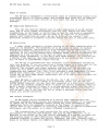
r-_.------
:OPT"iÖH;:i.-\jNITS-SHÖ'WH!
i'
IN BROKEN L1NES
1:
..
::--:----j- --- i
J---'" :
: 14 JL ~f === -:::--t-t------l
: : -----, L~ SYNC AM ~_-+ :
~
OETEtTOA. :
Pll)H
I
o
'2 kth
-~~--
r~~TORr-i
-----, t
I
I
I
: :
t_~.!~~T..o~J : :
t-Jr --- ... ------- ..... ----- -
i
I
l
I.------~r-IF-F-IL-T-E-R-S--'-:~"'--l
,
455
I
"
•
I
:
~
S-MI!:TE~
I
I
!
-:>.:.--
~H.
NPUT
..:,,
~
,
\ ~ ,.
'cl
~
I
\f
!
!
Pm:-~:
W
AH::",\
"l
CD
,,,
... --,
• """""
1
L_ .. o-_{:::~ -__ !
1-'
fl)
PLl UNLOCK
I t
I
r----------------------, CONTROL UNIT
I
I
i,
OISPlA~ ORIVER
_I RECEIVER
CONTROL REGISTER
-
---------------------------~=~~----
---i
REF6'O>".
KEV.All
~
: INTERFACE.
: --------
I
,
J
SER'AL BuS
I
I
I
I
I
~
"'EQUENCV
MEP-'lOAV
I
I
1L
lCD
FREQUENC~ DISPLA~
CDHTRDL
SWrTQlES
MODE
S'WJTCH
TUH'"
"',.." EHCOD..
HF -12
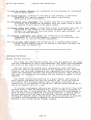
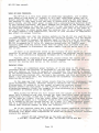
HF-125 User manual.
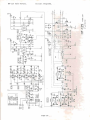
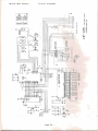
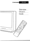
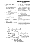
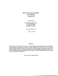
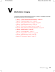
Circuit Description.
The HF-125 is a dual conversion superheterodyne receiver, using up
conversion to a high frequency first 1F of 45 MHz and a second 1F of 455 kHz
for the selectivity determining filters. This design gives good 1F image
rejection at all tuned frequencies in the HF band,. coupled with good filter
shape factors in the 455 kHz 1F.
Signals from the aerial pass through one of five band selecting filters
before the first mixer. These filters attenuate strong signals that are weIl
separated from the frequency being received, and help to reduce interference
from even order intermodulation distortion. Particular attention has been paid
to separating strong medium wave signals from the rest of the HF spectrum, and
to attenuating signals above 30 MHz which may be received as 1F images.
There is no RF stage be fore the first mixer, and this, coupled with the
use of a high performance transistor-tree mixer, gives the HF-125 a large
dynamic range and good resistance to overload. A four-pole crystal filter with
a 15 kHz bandwidth in the first 1F (at 45 MHz) limits the signals fed to the
second mixer and removes image responses from the second 1F.
Most gain in the receiver is in the 455 kHz second 1F stage, where
amplifiers and filters are interspersed in a chain. The receiver USeS cerarnic
multi-element filters in this 1F, and switches in as many as possible for a
selected bandwidth:
2.5 kHz bandwidth
2.5, 4 and 10 kHz filters
4 kHz bandwidth
7, 4 and 10 kHz filters
7 kHz bandwidth
7 and 10 kHz filters
10 kHz bandwidth
10 kHz filter.
At the end of the second 1F, a full-wave envelope detector serves as a
low-distortion AM detector and an AGC source. When excessive levels of signal
(noise spikes) are detected it fires a noise blanker monostable which in turn
mutes the audio output. The IF signal also feeds a product detector which is
used for detection in SSB and CW modes, when the 1F is mixed with a carrier
signal. Audio signal filtering is provided by a high Q peaked response filter
centred on 800 Hz which is switched in for the 400 Hz CW filter. The tone
control uses an R/C bridge circuit to give either LF or HF cut, with a central
flat response position.
Receiver tuning is achieved by varying the frequency of both the local
oscillator and the 1F conversion (heterodyne) oscillator. The local oscLllator
covers 45.030 to 74.999 MHz in 1kHz steps, and fine tuning is provided by the
heterodyne oscillator covering 44.544 to 44.545 MHz in 15.6 Hz steps. The
final carrier insertion frequency is determined by the mode selected so that
the 1F filter passband is in the correct position relative to the carrier for
USB or LSB reception.
Only the local oscillator signal is produced by a phase-locked-loop
frequency synthesiser, but all frequencies affecting the tuning of the
receiver are crystal derived to ensure good frequency accuracy and low drift
in operation.
All the switching and tuning functions in the receiver are under the
control of a dedicated microprocessor system, which.receives commands from the
front panel controls and sends information to the receiver control register
and the PLL system on serial data busses. The single-chip microprocessor is
supported by a controller driving the liquid crystal display and a frequency
memory chip with lithium battery supply backup. All these components are
mounted separately from the main RF and 1F circuits on a PCB behind the front
panel. The control system is designed to use the "static idle" principle,
whereby there are no signals (other than abasie clock oscillator) in the
system until the operator requires a change in the receiver condition. The
system then reacts to commands from the receiver's controls before returning
to its static condition once again. This method of operation virtually
eliminates spurious signals from the control system being picked up by the
receiver's input stages.
Page 19
Q1,3
Q2,6-Q
Q4
QS
01-11
012
013
014-26
SL6440C
BC183L
ZTX320
SL6700C
BA244
MI204
B~Y66 C5V1
IN4148
B·
5V
"
118-301
~IO
:.:::
"
"
'.,"
"
"
"
IW-18 I
J3
].'
IRF ATTEN[
IMIX
145 MHz
11
~
~
50g
Input
..
...
Whip Ant
AmplJfler
COMlet.lon
't:I
54321
~
RF Frlter SlllecL
RFA""1 NRFA
LO
11'I11
!"t.LI
LPLLI
(1)
5V
'"
o
1455 kHzl
)(2,.~.
~~~~~~~~~~~-----------~-
"
.,.~'
I
..
.
~
.,
, .,
. '...,.".
.
•
•I
," >".
~
I
--- --------
.. _
=:]
I-.LWJ ..J ,_,
.
AMU
I•
"
.".,~
~
-
~"
,
nn
n
+-+--1 TI
1~
IIF AMPj
IIF AMP 1
I~:;f ;J;Y~
'"
'"
=========--
-;::!
12345
IF FIlter Seloct
lj>l,l,J
IFQ'''I
CAR
fnLI
:-
I 1
·1
0\0,13
011,14,15
16,:15
01:1
017
018
01Q
J310
BC183L
020,21
022
0:13
024
028
027
0:18
ZTX3:10
UPB586C
MC145156P
BC212L
74HC40Q4P
74HCO:lP
LM3:l4N
4066P
LM380N
LM2Q30T-B
LM7SM05
LO
HEhn
lll:fl
8V
0:17,:18
D2Q-32
033,34
035-41
D42
BA244
BAW6:1
88222
1N4146
1N4002
C
IP'",,-~~~
!LOCAL
OSC
,,"0
leAR ose
I."
1 CIC~
I:oe
l.~llll
T'C:>.
"
f
>.7
.:.:. \H,
~U
..
l( $
'"
'",.,
l1f
)~~i~
.
,"'"
W:e
'"
,,,~--j
+-:3
'tl
llJ
lI~(O
I
~,
io, .
Jl~
W
('tl)
,,.,
IQ
~~~il~~::~
I ""~".'
I
CIQ&
.(10"
~1h
~l~
5V 5V
SV 8V
~Il
IAF FIL TER
I
~~-. c::::...-.:.c=c:..::.:..:.J
PLL
SYSTEM
100,
'"
r-'
sv
~:::
'-----
~~.I
5V 5V
lolo;oD
E~20
llJ I,t
eONTROL
REGISTERS
I
Y:1J,f11 i
1
.
5.J~
"
6+
~~
It~
II~~~
~~
i
j ,,1'2:'2
",.1
h:;;,~'
"'I .----'
. ;". j
.~
",h""
rnL Il0r
12345
12345
IF Fllt.r S,I••t
<
<
~:;:
~
,
Jttttt!ttp
16
•~ l H
5V 5V
RF Fllt.r S.ioet
5V
J'~q~~m~~nJQ
COl\flec:llon lCl Control Unrt
~L~Y:~
< ~
5V5V5V5V
1~
5V
-.L
5V
r----:l'"
902
Ol
~:
"
I ""
va
.4'1
tI
~l
~,
IRAM I :~
3
.t.04
Q2
..
It
~ ~
DA't
1ll)11
"1"0
C~
c•
n'J;
Q3
~fset
•
I
.l ~:.c,
1~'J;
.'"
"
'"
~~"l ~
"
""
IJ rr:: : :
.. "',
:~~
:~~
L5ff1
0'1000''''''
~'"
J"1
-~'l
I
" ".,
JP1
"
.,~
:;t=~~~~~I~111
~~~
OND,
'tI
DJ
I,Q
(1)
N
N
~
~.500Mi.
OM-:
'",,,
~
t
,
\'
JI
',.:J1
01'1'
8+
lfAlIf'I'
~Ul,.'
:~
1
1~
1
01"
Oll:.
OBfi
081
M'
..1 1
DD D
K.yp.d
Int.rfoc:.
Connectton
DtO
~".
»
~
J~~i,~~i:~
'"ll!
B+
,.
'Ij
B"
B+ B·
4'
.,:
0.
b?J
5
IV
5V
5~.
,.,.
1
'"
"
~
~:"' r
ll.
5V
,;", ,;", ,
"."
I
~
...
Q4
!DISPLAY DRIVER
"
CLOCIC "
~~
I
ISWITCH UNITI
I
,
,
,
I
,
I
I"'OUT '3
'."
... "
9U!N!S
~::t:1::t:1~tl:tt:l:l:l:l::t:1r:1:~tl:tttl:j:j:j:r:l:j:jJ J2.J3
'"
5V
.' ;J.' ~ .~
It
~TI ~ ~ Il\':; lIi
r ..
:~-~-Jj:=; /..}i Ji : ; l.~ .:: ~,~;:: " ~
c::=:J
r=:J
0
t=:I
LlDl
(=:J
r=:J
!LCD DISPLAY
I
S7b-'
.
~
0--
l
'O~O '0::0 '0:) ,() ,O:O"'~
,.,,, O' • '0 0 0'" 0 0 0 0 0 0
~
B·
alf 1
•
~~~9~~·O.~·~.~cO~
~
----------------IMODE
I
.~~ ..
.
[FMETER]
I
,;, !
~~~~
.....
~
H
HF-125 User manual.
Receiver specification.
Frequency coverage.
Detection modes.
30 kHz to 30 MHz continuous coverage.
Optionally 150 kHz to 26.1 MHz restricted
coverage.
AM
SSB (USB, LSB and CW)
FM (narrow bandl (Optional with D-125 unit)
Synchronous AM
10ptional with D-125 unit)
Tuning.
By spin-wheel - continuous tuning in
15.6 Hz steps. Step size increases
with faster tuning knob rotation.
MHz quick selection by push button.
Keypad frequency entry.
10ptional with
K-125 keypad unit and interface)
Memories.
30 frequency memories in two banks of 15,
with lithium battery backup.
I F Filter bandwidths.
2.5 kHz, 4 kHz, 7 kHz, 10 kHz
400 Hz audio filter ICW mode only. )
(Filters are user selectable)
Sensitivity.
SSB mode: <0.3 uV for 10 dB S/N
AM mode: <0.7 uV for 10 dB S/N @ 70% mod.
IFor received frequencies >500 kHz)
R.F.Attenuator.
User selectable 20 dB attenuator.
Dynamic range.
>90 dB at 50 kHz from tuned frequency.
>80 dB at 20 kHz from tuned frequency.
IMeasurements made in SSB mode with the
2.5 kHz filter, and cover both 3rd
order intermodulation and reciproca1
mixing effects.)
Image and spurious responses.
>75 dB rejection.
Audio output.
0.75 W into internal loudspeaker.
1.25 W into external 4 ohm loudspeaker.
Connections.
Antenna input : 50 ohm via SO-239 socket.
600 ohm + Gnd terminals.
Active whip antenna. (Optional P-125 unit)
External loudspeaker output - 3.5 mm jack.
Headphone output - 6mm mono/stereo jack.
Record output (100 mV) - 3.5 mm jack.
12V DC power input - 2.1 mm power jack.
Power supply.
Externa1 12V DC supply at approx 250 mA,
Internal NICAD batteries and charger to
give typically 8 hrs operation.
(Optional P-125 unit)
Size.
ApprOX 255 x 100 x 200 mm (WxHxDl
Weight.
Approx 1.8 kg <basic receiver)
Approx 2.5 kg with P-125 option fitted.
Specification subject to change without notice.
Page 23
HF-125 User manual.
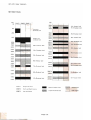
HF Band Plan.
kHz
kHz
30
150
7000
7100
7300
Lang wan
+Om Amatlur band
+lm Br••de.st b.nd
broadcast bond
Q500
285
31m Br••deolt b.nd
QqOO
10100
10150
525
Me.dlum ...ave
br.adeast bond
1606
1705
1800
160m Amotutur band
11650
12050
13600
13800
30m Amatlur band
25m Broadea.t b.nd
,
22m Br.adeast band
1+000
14350
2000
2300
20m Amatlur band
120m Broodeast bond
2500
15100
3200
15600
qm Sr.adeast band
QOm Braodeast band
16m Br.ade.st band
SOm Amatlur bond
15m Amatlur band
13m Sr ••de.lt band
75m Br ••deast band
60m Br.adeast band
11m Broodcost band
4Qm Br.adealt b.nd
iOm Amot,ur bond
ZONE 1
Eurap. and Arrlea
ZONE 2
N.rth ond S.uth Amtrlea
ZONE 3
ASla t10d
0 cgonle
-
~
Page 24
General broodcost. bond
~
Amatlur band
Tr.pleal broad.ost bond
CJ
Othor Iignal.
LOWE ELECTRONICS LIMITED
Chesterfield Road, Matlock, Derbyshire DE45LE
Telephone: 0629 2817, 2430, 4057, 4995 Telex 377482