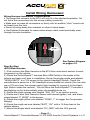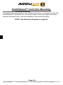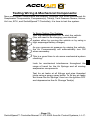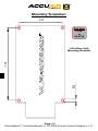
1
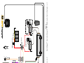
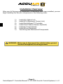
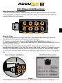
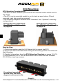
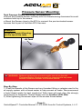
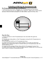
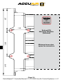
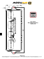
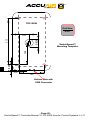
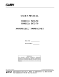
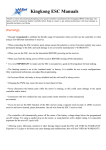
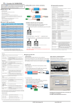
Installation Manual
SwitchSpeed™ Controller:
Congratulations!
Thank you for purchasing the revolutionary SwitchSpeed™ Controller by
AccuAir.
This air suspension controller manages up to 4 Air Springs as an intelligent
switchbox with user-adjustable control of valve speed. The AccuAir
SwitchSpeed™ also manages your Air Compressor(s) to keep onboard air
at an ideal pressure for your application (If Optional Electronic Tank Pressure
Sensor is connected).
To maximize functionality, the AccuAir SwitchSpeed™ allows you to select
from three distinct valve speeds:
1.) Full Speed.
2.) Medium Speed (Adjustable).
3.) Precision Speed (Adjustable).
The exact settings for each of these speeds is User Adjustable
(see page 10 in your Operation Manual).
!
WARNING: Extended valve pulsing MAY reduce the life of your
valves.
At AccuAir, we pride ourselves on thorough customer service, quality
products, and a better driving experience through technologically superior
design. Please visit our website or call us toll free to let us know if there is
any way that we can help improve your AccuAir experience.
(877) AIR-DOWN
247-3 6 9 6
Table Of Contents
Description
Terms & Conditions
Wiring Diagram
Installation Overview
Mounting & Wiring Instructions
Testing Mechanical & Electrical Hookup
Mounting Templates
Page Number
3
4-5
6
7-12
13
14-20
Terms & Conditions:
AccuAir Control Systems, L.L.C. is hereby referred to as ACCUAIR. The Purchaser, end-user, or installer is hereby referred to as CUSTOMER.
Warranty
ACCUAIR will repair or replace any failed components for the life of the vehicle
given that the components were installed and operated as intended by
ACCUAIR. Upon the return of a failed component(s), ACCUAIR will determine
the cause of failure. If it is due to improper installation, or misuse of the system,
a repair charge will be assessed and the customer will be contacted before
work is performed or replacement parts are shipped. If the failure is due to faulty
parts, then ACCUAIR will repair or replace the failed components at their own
discretion and in a timely manner.
Repairs and Returns
A Return Merchandise Authorization Number (RMA) is required for ALL shipments to AccuAir Control Systems. This number should be written in large
letters on the shipping box. Call AccuAir to receive an RMA number and send
items to:
AccuAir Control Systems, L.L.C.
Attn: Service Department/RMA # ______
1241 Johnson Ave. #355
San Luis Obispo, Ca, 93401
USA
Legal Disclaimer
•ACCUAIR’s products must be installed by a qualified professional installation
facility as recommended by ACCUAIR.
•System operation and installation is at the CUSTOMER’s own risk. ACCUAIR
accepts no liability for damage of property or persons caused by its products,
components, accessories, installation instructions or otherwise.
•ACCUAIR accepts no responsibility for systems, products or components
provided by other manufacturers for use with or around the ACCUAIR system.
For components other than ACCUAIR’s, follow the manufacturer’s instructions
for installation and operation.
!
WARNING: No part of the vehicle should be able to contact the
ground when all air is out of the air springs.
- Page 3 -
SwitchSpeed™ Controller Manual V1.2 © 2009 AccuAir Control Systems, L.L.C.
7
6
8
4
White/Black
White/Orange
White/Purple
White
White/Gray
White/Green
White/Brown
White/Blue
3
2
3
V_GND
P_SENS
EC_GND
IGN
ON
COMP_1
(F2) 3 Amp
Compressor
Relay Fuse
BATT_12V
(F1) 15 Amp
ECU Fuse
- Page 4 SwitchSpeed™ Controller Manual V1.2 © 2009 AccuAir Control Systems, L.L.C.
1.) Up 4
2.) Up 3
3.) Up 2
4.) Up 1
5.) Down 4
6.) Down 3
7.) Down 2
8.) Down 1
5
1
ECU
HEADLIGHTS
When using other MFG’s
valves:
1
SwitchSpeed™
Controller
OFF
IGN_12V
12 V Batt
4
Compressor 2 (Optional)
2
- Page 5 SwitchSpeed™ Controller Manual V1.2 © 2009 AccuAir Control Systems, L.L.C.
Compressor 1
Compressor(s)
Relay
(Main) 70Amp Fuse
FRONT
Installation Overview:
After your Air Springs and Suspension Components have been installed, you can
begin installing the AccuAir components in the following order:
1.)
2.)
3.)
4.)
5.)
6.)
7.)
Install VU4 (Valve Unit)
Install ECU (Electronic Control Unit)
Install SwitchSpeed™ Controller
Install Tank Pressure Sensor (Optional)
Install Air Compressor(s)
Install Wiring Harnesses
Test Wiring and Mechanical Components
! WARNING: Make sure to disconnect the vehicle battery ground
terminal throughout the wiring process.
- Page 6 SwitchSpeed™ Controller Manual V1.2 © 2009 AccuAir Control Systems, L.L.C.
VU4 (Valve Unit) Mounting:
Valve Mounting Considerations
• These valves are 100% weather-proof and can be mounted under vehicle.
• You will need to mount the ECU near the valves, so make sure that there is
enough space for both items.
Step-by-Step
1.) Find a flat location to mount the VU4. This should allow enough room for
the airlines to be inserted without too much bending.
2.) Transfer hole pattern from the VU4 Mounting Template on page 14.
3.) Drill holes with a 3/16” drill bit and bolt the VU4 down with the included #10-24
Allen head cap-screws.
4.) Place the ground eyelet from the VU4 wiring harness under one of the
cap-screws and make sure that this screw has good contact to chassis ground
with the included star washer. (Remove paint or coatings to expose bare metal)
5.) You may use this same location to place the ECU ground, so do not tighten
yet.
Ground Eyelet Installation
Wire Color Description
When using other
MFG’s valves:
V_GND
1
2
3
4
5
6
7
8
1.) Up 4
2.) Up 3
3.) Up 2
4.) Up 1
5.) Down 4
6.) Down 3
7.) Down 2
8.) Down 1
White/Black
White/Orange
White/Purple
White
White/Gray
White/Green
White/Brown
White/Blue
- Page 7 SwitchSpeed™ Controller Manual V1.2 © 2009 AccuAir Control Systems, L.L.C.
ECU Mounting:
ECU Mounting Considerations
• The ECU is 100% weather-proof and can be mounted under vehicle next to
the valves.
• The ECU can be mounted upright or on its back as seen below. (If back
mounted, back tabs must be removed)
• The following diagrams illustrate both “Standard” and “Optional” mounting
configurations.
Bottom Mounting (Standard):
See ECU Mounting Template
on page 16.
Back Mounting (Optional):
See ECU Mounting Template
on page 18.
Step-by-Step
1.) Find a flat location near the VU4 (Valve Unit) to mount the ECU.
2.) Plug-In the Valve Harness while finding the mounting position to make sure
that it reaches.
3.) Transfer hole pattern from the ECU Mounting Template on pages 16 & 18.
4.) Drill holes with a 3/16” drill bit and bolt the ECU down with the included
#10-32 Allen head cap-screws.
For optional mounting,
remove back tabs with
diagonal cutters and a file.
- Page 8 SwitchSpeed™ Controller Manual V1.2 © 2009 AccuAir Control Systems, L.L.C.
Pressure Sensor Mounting:
Tank Pressure Sensor Mounting Considerations
• Mount the Pressure Sensor vertically with the threads aiming downward to avoid
moisture build up in the sensor.
• Mount the Sensor close to the ECU to connect the pre-terminated sensor
harness that is part of the Main ECU Harness.
Example 1:
Pressure Sensor Mounting.
(In the top of the tank)
Air Tank
!
WARNING: Optional compressor control require use of an AccuAir
Pressure Sensor. System cannot be connected to any other
brand of Pressure Sensor or Pressure Switch.
Step-By-Step
1.) Coat the threads of the Sensor and any threaded fitting or adapter used in the
air supply system with a thread sealer to help prevent air leaks. We recommend
a liquid thread sealer for best results but Teflon tape will work also. We strongly
recommend an Anaerobic Thread Sealer such as Loctite’s (P/N: 565)
2.) After tightening the sensor wipe off the excess thread sealer.
- Page 9 SwitchSpeed™ Controller Manual V1.2 © 2009 AccuAir Control Systems, L.L.C.
Installing & Wiring Air Compressor(s):
Air Compressor(s) Mounting Considerations
• There should be a fuse in between the Compressor(s) and the battery.
• The Compressor(s) get very HOT during operation. Make sure to leave space
between items that are susceptible to heat. (Wires, Nylon-Air Line, etc.)
Step-By-Step
1.) Find a location for the Compressor(s) to be mounted with good air
circulation.
2.) Transfer the hole pattern of the Compressor using the Air Compressor as
your template.
3.) Drill holes and bolt the Air Compressor(s) down.
4.) Install the Power Wire to the vehicle battery (12v+) with an inline fuse
(30amps per Compressor) that is included with your Compressor(s) near the
vehicle battery (12v+).
5.) Install the Compressor Relay inline with the Compressor’s power line.
6.) Install the Ground Wire to vehicle/chassis ground. (Make sure to remove any
rust or paint to ensure a thorough ground)
- Page 10 SwitchSpeed™ Controller Manual V1.2 © 2009 AccuAir Control Systems, L.L.C.
Install Wiring Harnesses:
Wiring Harness Installation Considerations
• The plugs that connect to the ECU will only fit in the desired orientation. Do
not force the connectors into the wrong mating connector.
• Make sure to press all connectors on firmly until an audible “click” sound can
be heard from the lock.
• Route all wiring away from exhaust or other hi-temp areas.
• Use Rubber Grommets for areas where sharp metal could eventually wear
through the wire insulation.
CLICK !
See System Diagram
on pages 4-5.
Step-By-Step
•ECU Main Harness
1.) First connect the Main Harness at the ECU then route each section to each
component on the vehicle.
2.) Route the SwitchSpeed™ harness (Mini USB Cable) to the inside of the
vehicle and leave until later in installation. Route the single purple wire labeled
“HEADLIGHTS” to a 12V source in the vehicle Headlight Switch. Check the
manufacturer’s specs for a 12V Headlight source inside the vehicle (You can also
use a 12V wire from the closest marker light instead of running it to the Headlight Switch inside the vehicle.). This will allow the SwitchSpeed™ Controller’s
backlighting to dim automatically when the headlights are on.
3.) Route the single orange wire labeled “IGN_12V” to an ignition source.
4.) Route the 3-wire Tank Pressure Sensor sub harness (green, red, and black
wires) labeled “P_SENS” to the sensor.
5.) Route the single yellow wire labeled “COMP_1” to trigger the Compressor
Relay(s).
6.) Route the single red wire labeled “BATT_12V” with a 15 Amp fuse to the
vehicle battery.
7.) Mount the single black wire labeled “EC_GND” with the VU4 ground.
- Page 11 SwitchSpeed™ Controller Manual V1.2 © 2009 AccuAir Control Systems, L.L.C.
SwitchSpeed™ Controller Mounting:
SwitchSpeed™ Controller Mounting
• Choose a mounting location that will allow the driver to operate and view the
SwitchSpeed™ Controller from the driver’s seat. Once your target mounting
position has been found, use the template to drill mounting holes.
NOTE: See Mounting Template on page 20.
- Page 12 SwitchSpeed™ Controller Manual V1.2 © 2009 AccuAir Control Systems, L.L.C.
Testing Wiring & Mechanical Components:
Now your system components are installed, plumbed, and wired (Mechanical Air
Suspension Components, Compressor(s), Tank(s), Tank Pressure Sensor, Valves,
Air Line, ECU, and SwitchSpeed™ Controller), it is time to test the system.
To Begin Testing The System:
Turn the vehicle Ignition ON, or start the vehicle.
(You will need to be charging your electrical
system either by running the vehicle or by using a
high amperage battery charger).
As you consume air pressure by raising the vehicle,
the Air Compressor(s) will automatically turn ON
when necessary.
This is a good time to do some mechanical system
checking:
Look for mechanical interference throughout the
range of travel for the Air Springs and all moving
suspension components.
Test for air leaks at all fittings and pipe threaded
joints using a soapy spray bottle. To fix any air leaks
first lower the Air Springs, then turn the Ignition OFF
and depressurize the Air Storage Tank(s).
- Page 13 SwitchSpeed™ Controller Manual V1.2 © 2009 AccuAir Control Systems, L.L.C.
Mounting Templates:
2.45
Drill Size:
13/64”
or
#6,#7,#8
0.20
4.70
VU4 (Valve Unit)
Mounting Template.
- Page 14 SwitchSpeed™ Controller Manual V1.2 © 2009 AccuAir Control Systems, L.L.C.
2.27
Drill Size:
13/64”
or
#6,#7,#8
1.50
2.68
Bottom ECU
Mounting Template.
(Standard)
6.93
Minimum leave clear
space for connectors
- Page 16 SwitchSpeed™ Controller Manual V1.2 © 2009 AccuAir Control Systems, L.L.C.
1.01
2.02
Drill Size:
13/64”
or
#6,#7,#8
6.53
Rear ECU
Mounting Template.
(Optional)
- Page 18 SwitchSpeed™ Controller Manual V1.2 © 2009 AccuAir Control Systems, L.L.C.
TOP VIEW
Drill Size:
5/32”
Ø 0.50
3.13
0.59
0.40
1.46
SwitchSpeed™
Mounting Template.
0.40
1.45
Bottom Side with
USB Connector
- Page 20 SwitchSpeed™ Controller Manual V1.2 © 2009 AccuAir Control Systems, L.L.C.