1
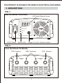
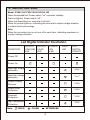
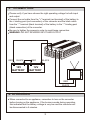
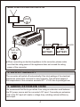
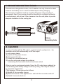
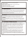
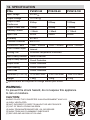
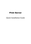
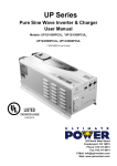
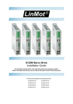
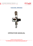
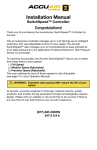
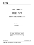
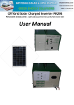
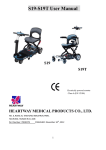
CONVERTS 24 VOLT DC INTO 12 VOLT DC POWER
DC TO DC CONVERTER
SWITCHMODE
INSTRUCTION MANUAL
Please read user manual before use.
THIS PRODUCT IS SUITABLE FOR USING DC ELECTRICAL APPLIANCES.
1. DESCRIPTION
FIG 1
Rear (50,000mA-100,000mA)
LED Digital Display Screen
VOLTS
LOAD %
Output Voltage
Output Load %
Power On
STATUS
Fault
On/Off Switch
Status LEDs
Voltage & Load % Selection Button
FIG 2
Front (50,000mA-100,000mA)
POS. Terminal
NEG. Terminals
POS. Terminal
DC INPUT
DC OUTPUT
20-30V
12-13.8V
1
2. INDICATING SIGN
Model: PV2412-50 PV2412-60 PV2412-100
Green illuminated led: Power switch "on" converter standby.
Green unlighted: Power switch "off ".
When red illuminated on: converter is at fault..
When the yellow lights on: indicating the converter's output voltage situation
or output load in percentage.
Note:
When the converters turn on or turn off in each time, indicating acquiesce in
a output voltage situation .
Led Digital Indicator Illustration
CONDITION
OUTPUT
VOLTAGE
LED
OUTPUT
LOAD
LED
POWER
ON
LED
FAULT
LED
LED
DIGITAL
DISPLAY
Power Off
Power On
Input high voltage
protection
" HHH "
Input low voltage
protection
" LLL "
Output Polarity
Reverse
" LOH "
Output Short
Protection
" LOH "
Overload
Protection
" LOH "
High Temperature
Protection
" FOH "
Note:
: SOLID
: FLASH
: EXTINGUISH
2
3.CONNECTION
Please verify if you have chosen the right operating voltage for both input
and output.
Connect the red cable from the "+" terminal (red terminal) of the battery to
the + binding post (red connection) of the converter and the black cable
from the "-" terminal (black terminal) of the battery to the "-" binding post
(black connection) of the converter.
Be sure to tighten the screws in order to avoid loose connection.
WARNING: DO NOT REVERSE INPUT AND OUTPUT
DC INP
20-30
UT
V
DC OUT
12-13
RED
BLACK
12V
BATTERY
RED
PUT
.8V
BLACK
12V
BATTERY
RED
BLACK
4. OPERATION
When connected to an appliance, remember to turn on the converter
before turning on the appliance. If the buzzer sounds during operation,
this indicates that the battery voltage is very low and the converter will
be disconnected in 5 minutes.
3
Model: PV2412-50 PV2412-60 PV2412-100
"Turn on"
secondly
VOLTS
LOAD
Outp ut
Volta
Outp ut
Load
Powe
Fault
%
ge
%
r On
STATUS
RED
BLACK
12V
BATTERY
"Turn on"
firstly
RED
BLACK
12V
BATTERY
When connecting an electrical appliance to the converter, please make
sure that the rating power of the appliance does not exceed the rating
power of the converter.
5. OUTPUT CAPACITY
The converter will switch off automatically if the total wattage of the electrical
appliances exceed the converter's output capacity. This will also happen if
the temperature of the converter exceeds 65℃ +/-10% due to prolonged use.
6. ADDING EXTENSION CORD
We recommend that the buyer refrain from using an extension cord between
the DC power source and the converter's DC input. Connecting an extension
cord to the DC input will create a voltage drop, entailing reduced efficiency
and output.
4
7. MOUNTING INSTRUCTIONS
Converters are designed for indoor, out of weather use only. Ensure that both
converter and battery are in a well-ventilated space during charging.
The converter end plates include a mounting flange for easy mounting. If
permanently fixed, the converter should be mounted to a suitable horizontal
or vertical panel, with at least 10cm clearance from the end plates to provide
adequate ventilation for the cooling fan.
VOLTS
LOAD
Output
Output
Pow er
Fau lt
%
Volt age
Loa d
%
On
STATUS
4.0mm
mounting hole
8. CAUTION
In case of trouble with the DC output, e.g.short-circuit, overload, etc... the
protection circuit will automatically cut off the output.
In such cases, please
(A) switch off the power at once
(B) disconnect all units
(C) check the connected devices
(D) use the units again unless the problems
concerning the connected devices have been solved
When in use for a prolonged period of time, the DC output may suddenly be
cut off although the battery voltage is still very strong. This may be caused
by excessive temperature.
If this happens. Please proceed as follows:
(A)Switch off the converter at once
(B)Disconnect some of the appliances or wait until the converter cools off
(C)Switch the inverter back on
5
Always keep the converter in an environment which is:
(A)Well-ventilated
(B)Not exposed to direct sunlight or any other heat source
(C)Inaccessible to children
(D)Safe from water/moisture, oil or grease
(E)Safe from any flammable substance
9. MAINTENANCE
Very little maintenance is required to keep your converter operating properly.
You should clean the exterior of the unit periodically with a damp cloth to
prevent accumulation of dust and dirt. At the same time, tighten the screws
on the DC input and DC output terminals.
10. NOTE
All specifications are typical at nominal line, half load, and 25℃ unless
otherwise noted. Specifications are subject to change without notice.
WARNING:
DO NOT DISASSEMBLE THE UNIT. HAZARDOUS VOLTAGE! DANGER!
PLEASE RETURN TO THE DEALER IF YOU FIND ANY PROBLEM WITH
THE UNIT.
11. SUITABLE POWER SOURCE
In order to operate the converter and supply power to an appliance, a
suitable 24V DC power supply is required. This can be a vehicle or caravan
battery, portable power pack or an independent 24V lead acid battery,
For most applications, a deep cycle battery is recommended for best
performance..
The size of the battery used will determine how long the converter will
supply power to an appliance and how well the converter will perform.
Most batteries are marked with their size in Amp hours (AH) or Cold
Cranking Amps.
Because converter are capable of drawing high current, the converter
should only be connected to a suitable size battery. Connection to an
undersized battery could damage the battery and will result in the
converter shutting down within a short period due to low battery voltage.
The amount of power dawn from the battery is proportional to the converter
load.
6
12. SPECIFICATION
P/No.
PV2412-50
Input Voltage
20-30V
PV2412-60
PV2412-100
Output Voltage
12-13.8V
Output Power
Continuous
50Amp
60Amp
100Amp
Output Power Max
70Amp
80Amp
130Amp
Standby Current
≤90mA
≤90mA
≤110mA
Input Fuse
2x30A
2x40A
4x30A
Efficiency
85~90%
Thermal Protection
O
65C+/-5
CO
Connection Cable
10mm 2/ 900mm
12mm 2/ 900mm
20mm 2/ 900mm
Fuse Location Input
Internal
Cooling Fan
Automatic temperature controlled
Input Polarity Reverse
Diode Protection
Output Polarity Reverse
Circuit Protection
Output Short
Circuit Protection
Over Heating
Circuit Protection
Over Load
Circuit Protection
Dimension (L x W x H)
275x165x79mm
275x165x79mm
365x165x79mm
Weight
1.9Kg
1.9Kg
3.1Kg
Specifications are subjected to change without prior notice.
WARNING:
To prevent fire shock hazard, do not expose this appliance
to rain or moisture.
CAUTION:
ALWAYS PLACE THE CONVERTER IN AN ENVIRONMENT WHICH IS:
(A) WELL VENTILATED.
(B) NOT EXPOSED TO DIRECT SUNLIGHT OR HEAT SOURCE.
(C) OUT OF REACH FROM CHILDREN.
(D) AWAY FROM WATER/MOISTURE, OIL OR GREASE.
(E) AWAY FROM ANY FLAMMABLE SUBSTANCE
(F) SECURE AND NO RISK OF FALLING.