1
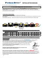
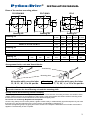
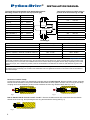
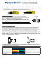
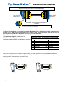
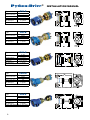
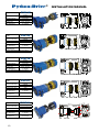
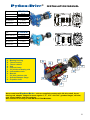
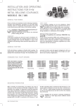
Python-Drive®
INSTALLATION MANUAL
Installation manual
www.pythondrive.com
2010
1
Python-Drive®
INSTALLATION MANUAL
For units supplied by manufacturer after January 2007
2010 (c)
For the models ranging from P30-R up to P1000-G
May we take this opportunity to thank you for purchasing a Python-Drive flexible drive shaft assembly, your
Python-Drive assembly is supplied complete with all the necessary bolts, screws, washers and nuts required.
Please find below instructions designed to assist you during the assembly process. We recommend you read this manual
before the actual process of installation.
1) Transmission adaptor flange.
Check that the flange dimensions match your transmissions output flange.
All fixing bolts and nuts use locking washers, please ensure they are used as directed below and are tightened to the correct
torque settings.
As indicated by drawing No. 1, Make sure that studs are screwed in with the short threaded part in the adaptor flange.
Drawing 1
Fit and tighten the bolts and nuts using following torques (the tightening torques for the internal clamps can be
found separately in chapter 3 of this manual) :
M8
3/8”UNF
M10 7/16” UNC M12
½” UNC
M14 M16 M18
3/4" UNC
M20 M22 M24 1”UNC
Nm
34
58
66
83
120
125
180
280
400
500
560
750
950
1040
Lb.ft.
25
43
49
61
88
91
132
205
295
368
413
406
700
765
We would recommend that all fixing bolts, nuts and threads are free of (dust)particles and grease,
prior to assembly.
2) Mounting plate
Due to the variations in hull design and material it is not possible for Python-Drive to supply mounting
plates. We would ask you to remember, when designing a mounting plate it must be able to support the
forces transmitted by the propeller. For plate dimensions refer to drawing No. 2A, 2B and 2C.
The mounting plate should be at right angles to the prop shaft both vertically & horizontally,
as indicated below with drawing No. 2. Prior to positioning the mounting plate please
90º
ensure all distances have been correctly measured.
The thrust bearing assembly should be mounted on the propeller side of the mounting
plate, as indicated by drawing No. 3
Fixate the mounting plate under an angle of 90º compared to the
propeller shaft as shown in drawing No. 2.
90º
Drawing 2
Watch the video how the HBV Lock Systems perform compared to other products – Click here –
The test proves the superiority of the HBV Lock Systems; even when all other locking systems fail, the HBV Lock
washers keep the connection intact. Extreme shocks and especially vibrations are smoothly absorbed and have no
influence on the tightening torque of the bolt/nut connection. The test is both simple as well as effective; a vibration
in radial direction is unleashed on the bolt/nut connection while a load-cell continuously measures the tension
(=tightening torque)
2
Python-Drive®
INSTALLATION MANUAL
Sizes of the various mounting plates:
PD-R/B/K/M/S
PD-T/Q/W/L
A
PD-G
A
B
A
B
B
D
D
C
D
E
C
G
E
C
E
F
Drawing 2A
Drawing 2C
Drawing 2B
A
in mm
B
in mm
C
in mm
D
in mm
E
in mm
P30-R / PD-R
143
106
53
25
NA
P60-B / K / PD-B / K
157
120
60
30
NA
P80-M / S / P110-S / PD-M / S
170
140
70
35
NA
A
in mm
B
in mm
C
in mm
D
in mm
E
in mm
P110-T / P140-T / P200-T / PD-T / P200-Q / P501-Q / PD-Q
230
184
92
40
68
P200-W / P501-W / PD-W / P1000-L / PD-L
280
230
115
50
66
Drawing 2A
Drawing 2B
Drawing 2C
A
mm
B
mm
C
mm
D
mm
E
mm
F
mm
G
mm
P1000-G / PD-G
436
250
125
>50
113
384
5
Arrangement bolts, nuts and thrust-blocks
er
ell
op
Pr
Trust bearing
e
gin
En
er
ell
op
Pr
Mounting plate
e
gin
En
All models which carry the letter
‘R’, ‘B’ ‘K’, ‘M’, ‘S’ in the part No.
Drawing 3
All models which carry the letter
'T', 'Q', 'W', ’L’, or 'G' in the part No.
Please Note: The thrust bearing units of all models are electrically isolated i.e. there is no metal
connection between the thrust bearing unit and the mounting plate.
3) Prop shaft to thrust bearing internal clamping:
The clamping force is transmitted by contact pressure and friction between the mating surfaces, the condition of the
contact surfaces and the correct tightening of the locking screws are essential. All contact surfaces including screw
threads and screw head contact surfaces must be clean and slightly oiled.
Do not use oils containing Molybdenum Disulphide!
Once the ring clamp is in its correct position, tighten screws evenly in a diametrically opposite sequence by not more
than half a turn per time tightening to the correct torque, as indicated by drawing No. 4.
Recheck the tightening torque by going around the screws in the sequence described until no further movement is
apparent. The assembly is then complete.
3
Python-Drive®
INSTALLATION MANUAL
The length of the prop shaft has to be determined as follows:
Mounting-surface CV joint to end of propshaft (A)
Total length of the prop shaft, which is
pushed in the thrust bearing unit (B)
P30-R / P60-B
14 - 20 mm
P60-K
14 - 20 mm
90 -
96 mm
P80-M / P80-S
16 - 20 mm
115 -
119 mm
P110-S
16 - 20 mm
115 -
119 mm
P110-T/P140-T
16 - 22 mm
123 -
129 mm
P200-T/P200-Q
24 - 31 mm
144 -
151 mm
P200-W
24 - 35 mm
180 -
191 mm
P501-Q
32 - 39 mm
161 -
168 mm
P501-W/P501-L
32 - 45 mm
180 -
193 mm
P1000-L
32 - 45 mm
200 -
213 mm
P1000-G
32 - 45 mm
60 -
B
Schroefas
Propshaft
A
66 mm
depending on execution
Drawing 4
Model
Thread / torque
P30-R / P60-B
M6 - 14 Nm
P60-K
M6 - 17 Nm
P80-M / P80-S / P110-S / P110-T / P140-T
M6 - 17 Nm
Thread / torque
M8 - 41 Nm
P200-T / P200-Q / P501-Q / P200-W / P501-Q
M8 - 41 Nm
M10 - 83 Nm
P501-W / P501-L / P1000-L / P1000-G
M8 - 41 Nm
M10 - 83 Nm
P1000-G
M12 - 145 Nm
In applications where a prop shaft is used with a relatively small shaft diameter and this in combination with a Python-Drive
model with a relatively high maximum torque, the unit comes with an extra clamp unit, which is inserted at the rear of the hub of the
thrust bearing unit. In such cases, the installation instructions of these clamps are supplied with the clamp. Depending on the actual
maximum torque, such a situation is possible, when the shaft diameter is smaller than the minimum shaft diameter as given in the
leaflet.
In some cases of extremely high torque, again in combination with a relatively small shaft diameter, it is possible, that a 'Shrink Disc' will
be added to the thrust bearing unit. The bolts of the ‘Shrink Disc’ are to be tightened with 30 Nm in the same manner as described for
the internal clamps.
Removal of internal clamp:
Loosen the locking screws in a diametrically opposite sequence P30-R /P60-B : Remove all allen screws, then M8
bolts should be screwed in the pull out threads located under the silver-plated screws. The front ring of the clamp
coupling can then be released (under normal conditions the front ring releases itself). See Fig. 1 & 2
Fig. 1
Fig. 2
P60-K / P80-M / P80-S / P110-S / P110-T / P140-T: Remove all allen screws and screw these into the release
threads of the front ring, thus pressing the rear ring and release the clamp (see Fig. 3)
Fig. 3
4
Python-Drive®
INSTALLATION MANUAL
P200-T up to P1000-G: remove all allen screws as previously described and screw them in the threaded bores in
the front ring and release it (Fig. 4). Then screw the allen screws in the central flange and release the rear thrust ring
(Fig. 5). Some of the units have a Shrink Disc coupling at the propeller-side of the thrust bearing unit, which is easily
removed by simply loosening all the screws. For same applications an internal clamp coupling is used at the rear of
the thrust bearing unit, which can be released in the same way as described with Fig. 3
Fig. 5
Fig. 4
4) Anti-vibration assembly:
Drawing 5
The silent rubber blocks should be mounted as indicated in drawing No. 5.
P30-R: silent rubber blocks should be compressed to 13 mm., P60-K to 16 mm and
P80-S up to P1000-L to 15 mm. as indicated in drawing No. 5
Please note : should the mounting plate not be at right angles to the prop shaft,
adjustment is possible by shimming between the rubber blocks and the mounting plate.
Model PD-G / P1000-G has polyurethane thrust blocks,where the above
described ‘compression’ does not apply, but shimming may be neccessary.
A
5) Drive shaft lengths and angles:
We recommend the flexible drive shaft installation lengths and angles are thoroughly checked. This procedure is
important, due to the movement that may be inherent within the installation. Where engines are mounted on flexible
mounts, there is always a tendency for the installation to move fore and aft, in addition to port and starboard.
Allowing for plus or minus 2 mm. the net length of the flexible drive shafts of the models from P30-K to P140-T and
for plus or minus 3 mm. for P200 and P501, can be taken from the drawings attached to this manual (these
dimensions = L as indicated in drawing No. 6). For model P1000 also see these drawings (allowing for plus or minus
12 mm. ), see last pages of this manual. A simple way to determine the actual length is to measure both the longer
side and the shorter side and to average them out. This must be the length of the flexible shaft you have chosen. If the
location points are out in more than one plane, measure both planes as previously described and average the two sets
of figures, as indicated by drawing No. 6 and No. 7
1
L
2
Drawing
Drawing 6 6
Drawing 7
Drawing
7
The P30 up to the P110 drive shafts have coloured ‘O’ rings which hold the boot covers in place. The P140 has clamps
which hold the boot cover of the CV joint in place, where one has a coloured tag to identify the net length of the CV
drive shaft. The meaning of the colours is as follows:
P30/60/80-145 mm
WHITE
standard length for P30-R and P60-B
P30/60/80-165 mm
BLUE
standard length for P60-K
P30/60/80-195 mm
BLACK
standard length for P80-S
P110-180 mm
YELLOW
P110-225 mm
RED
GREEN
standard length
BLACK
P140-180 mm
BLACK
P140-225 mm
BLUE
standard length
5
Python-Drive®
INSTALLATION MANUAL
Hub of thrust
bearing unit
Python-Drive
Tip: Measuring of the length of Python-Drive CV drive shafts where models P200 and
larger fit in recesses in the hub and the adaptor flange
Adaptor flange
for gearbox
Net length (as shown in our leaflets and manuals)
for standard versions of P200 and larger CV
drive shafts
Note: when the CV drive shaft is mounted, the length can only be checked by deducting
the 'height' of the rim of the recess of both sides.
Important; we recommend that the drive shaft “constant velocity” joint angles at either end of the shaft are
installed correctly. Under no circumstance should a Python-Drive flexible drive shaft be installed at Zero
angles (in line). To do so will greatly shorten the life of the CV joint, causing premature failure due to a loss of
bearing efficiency/lubrication. A minimum of 1,5º per joint is recommended.
The maximum angle of installation of the
maximum angles and maximum propshaft RPM
Python-Drive CV joint and the maximum
P30 - P140
P200 – P1000
operating propshaft RPM is as indicated by chart No. 8
8º
0 - 1000 rpm.
7º
1500 rpm.
6º
2000 rpm.
5º
2500 rpm.
4º
3500 rpm.
3º
4500 rpm.
4º
1200 rpm.
3.5° 1500 rpm.
3°
1750 rpm.
2.5° 2250 rpm.
2°
3000 rpm.
Chart No. 8
Ideally the CV joints should be mounted at approximately the same angle. If this is not possible ánd the difference
between the angles of the front and rear CV joint would be greater than 5º, the CV-joints could become subject to
abnormal loads, maybe resulting in premature wear.
Drawing No. 9 shows the ideal set-up and drawing No.10 shows a less ideal set-up.
Fig. 3 9
Drawing
6
Fig. 4 10
Drawing
Python-Drive®
INSTALLATION MANUAL
CV Drive shaft assembly:
Fit the shaft into place loosely, ensuring the threads of both sets of bolts are engaged as to the tightening procedure.
Proceed to tighten the bolts in a diametrically opposite sequence to the correct torque, as indicated in the table under
drawing No.1
Please note: All P1000 models require filling with grease, (see under 7 below), which is supplied in the parcel.
6) Python-Drive maintenance:
•
•
•
All thrust bearing units are maintenance-free as they have life-time lubrication.
The following CV joints are supplied with lifetime lubrication and are therefore maintenance free: P30, P60, P80,
P110, P140, P200, P501.
All P1000 models require filling with grease prior to being installed in the boat.
Grease is supplied as part of the kit, and should be filled flush with the top surface of the CV joints.
Too much grease will automatically result in leakage causing the excess grease to be thrown out by the centrifugal
force.
Insufficient grease will cause premature failure due to lack of lubrication. When servicing, always ensure you use
the correct specification grease to Orly TP210 NLGI 1 - 2 DIN KP2K-20.
7) Assembly checks:
•
•
•
•
•
•
•
•
•
•
Ensure all washers are correctly located.
Check studs, bolts and nuts are tightened to the correct torques (use a torque wrench!)
Check required shaft lengths
Check installation angles
Check clamping surfaces are free of knocks or damage, which may prevent a face to face contact.
Check for surface damages of the drive / thrust assembly
Check the adjustment of the flexible engine mounting feet; as manufacturers use different instructions for their own
make of mounts. Most manufacturers will allow you to pair wise adjust the load/compression of the left and right
flexible engine mounting feet between 0 to 1 mm. Some manufacturers however won’t allow for any differences.
Check both front and rear pairs.
Prior to engine start up ensure the prop shaft rotates by hand and that all tools have been removed.
It is essential that the engine, gearbox, torsional damper, propeller size and Python-Drive model are
correctly matched, so that the engine can attain its rated speed appropriate to the relevant service
classification without labouring.
It is also important to ensure the torsional compatibility of the complete propulsion system from engine
through to propeller, since disregarding this may result in gear noise. In addition, it may result in damage
to the engine as well as to drive line components.
The manufacturer of Python-Drive will provide all possible information and assistance to help find
solutions to potential torsional problems. However, it is the ultimate responsibility of the person assembling
the drive and driven equipment to ensure that they are torsionally compatible.
7
Python-Drive®
Type
P30-R
30 kgm
294 Nm
Propeller shaft diam.
19 - 30 mm
Maximum prop. thrust
4.3 kN
Example use
50 HP / 3000 rpm
with diesel engine
2.5:1 gearbox
CV drive shaft optional lengths 145, 165 or 195mm.
Maximum shaft torque
Type
P60-B
60 kgm
588 Nm
Propeller shaft diam.
1.25" - 40 mm
Maximum prop. thrust
5.7 kN
Example use
70 HP / 2600 rpm
with diesel engine
3:1 gearbox
CV drive shaft optional lengths 145, 165 or 195mm.
Maximum shaft torque
Type
P60-K
60 kgm
588 Nm
Propeller shaft diam.
30 - 40 mm
Maximum prop. thrust
5.7 kN
Example use
70 HP / 2600 rpm
with diesel engine
3:1 gearbox
CV drive shaft optional lengths 145, 165 or 195mm.
Maximum shaft torque
Type
P80-M
80 kgm
785 Nm
Propeller shaft diam.
30 - 45 mm
Maximum prop. thrust
8 kN
Example use
105 HP / 3000 rpm
with diesel engine
3:1 gearbox
CV drive shaft optional lengths 145, 165 or 195mm.
Maximum shaft torque
Type
P80-S
80 kgm
785 Nm
Propeller shaft diam.
30 - 45 mm
Maximum prop. thrust
12 kN
Example use
130 HP / 2400 rpm
with diesel engine
2:1 gearbox
CV drive shaft optional lengths 145, 165 or 195mm.
Maximum shaft torque
8
INSTALLATION MANUAL
Python-Drive®
Type
INSTALLATION MANUAL
P110-S
110 kgm
1.080 Nm
Propeller shaft diam.
35 - 45 mm
Maximum prop. thrust
12 kN
Example use
135 HP / 2700 rpm
with diesel engine
3:1 gearbox
CV drive shaft optional lengths 180 or 225 mm.
Maximum shaft torque
Type
P110-T
110 kgm
1.080 Nm
Propeller shaft diam.
35 - 50 mm (2")
Maximum prop. thrust
18 kN
Example use
180 HP / 2400 rpm
with diesel engine
2:1 gearbox
CV drive shaft optional lengths 180 or 225 mm.
Maximum shaft torque
Type
P140-T
140 kgm
1.370 Nm
Propeller shaft diam.
40 - 55 mm
Maximum prop. thrust
18 kN
Example use
190 HP / 2500 rpm
with diesel engine
2.5:1 gearbox
CV drive shaft optional lengths 180 or 225 mm.
Maximum shaft torque
Type
P200-T
Propeller shaft diam.
Maximum prop. thrust
Example use
with diesel engine
200 kgm
1.960 Nm
40 - 60 mm
18 kN
240 HP / 2300 rpm
2.5:1 gearbox
Type
P200-Q
Maximum shaft torque
Maximum shaft torque
Propeller shaft diam.
Maximum prop. thrust
Example use
with diesel engine
200 kgm
1.960 Nm
45 - 60 mm
22 kN
250 HP / 2800 rpm
3:1 gearbox
9
Python-Drive®
Type
P200-W
Propeller shaft diam.
Maximum prop. thrust
Example use
with diesel engine
200 kgm
1.960 Nm
50 - 60 mm
30 kN
275 HP / 2500 rpm
2.5:1 gearbox
Type
P501-Q
Maximum shaft torque
Maximum shaft torque
INSTALLATION MANUAL
500 kgm
4.900 Nm
50 - 60 mm
22 kN
300 HP / 2000 rpm
3:1 gearbox
Propeller shaft diam.
Maximum prop. thrust
Example use
with diesel engine
Recommended rpm
Max. 1500 rpm
PD-Q thrust unit
CV drive shaft optional lengths 221 or 260 mm
Type
P501-W
500 kgm
4.900 Nm
Propeller shaft diam.
50 - 80 mm
Maximum prop. thrust
30 kN
Example use
400 HP / 2200 rpm
with diesel engine
3:1 gearbox
CV drive shaft optional lengths 221 or 260 mm
Maximum shaft torque
Type
Maximum shaft torque
P501-L
500 kgm
4.900 Nm
50 - 80 mm
45 kN
500 HP / 2200 rpm
3:1 gearbox
Propeller shaft diam.
Maximum prop. thrust
Example use
with diesel engine
Recommended rpm
Max. 1500 rpm
PD-L thrust unit
CV drive shaft optional lengths 221 or 260 mm
P1000-L
Recommended rpm
PD-L thrust unit
Max.1500 rpm
Maximum shaft torque
10
M16
222
140
66
662 ±12
520 ±12
77
245
280
340
Propeller shaft diam.
Maximum prop. thrust
Example use
with diesel engine
1000 kgm
9.810 Nm
70 - 80 mm
45 kN
750 HP / 2000 rpm
3:1 gearbox
Python-Drive
Type
352 ±12
65
P1000-L
Python-Drive®
P1000-G
Type
Propeller shaft diam.
Maximum prop. thrust
Example use
with diesel engine
1000 kgm
9.810 Nm
70 - 100 mm
60 kN
800 HP / 1900 rpm
3:1 gearbox
Recommended rpm
PD-G thrust unit
Max. 1500 rpm
Maximum shaft torque
P1500-G
Type
Propeller shaft diam.
Maximum prop. thrust
Example use
with diesel engine
1500 kgm
14.715 Nm
80 - 100 mm
60 kN
950 HP / 1900 rpm
3:1 gearbox
Recommended rpm
PD-G thrust unit
Max. 1500 rpm
Maximum shaft torque
A.
B.
C.
D.
E.
F.
G.
H.
I.
J.
K.
INSTALLATION MANUAL
Bearing housing
Thrust bearing
Thrust rubbers
Hub
Internal clamp
CV joint thrust bearing side
Intermediate shaft
Boot kit
CV joint gearbox side
Gearbox adaptor flange
Propeller shaft
A
B
G
F
H
J
I
E
K
D
C
Above mentioned Python-Drive units are supplied complete with CV-drive shaft, thrust
bearing unit, adaptor flanges for most regular 4”, 5”, 5.75” and 7.25” gearbox flanges, all bolts,
nuts, thrust-rubbers and lock washers.
Also included is an easy to read INSTALLATION MANUAL.
11