1
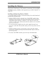
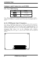
ET850
AMD Athlon™ II / Turion™ II Neo CPU
785E + SB820M
COM Express (Type II) CPU Module
USER’S MANUAL
Version 1.0A
Acknowledgments
PS/2 is a trademark of International Business Machines
Corporation.
AMD and Athlon™ II Neo are registered trademarks of Advanced
Micro Devices, Inc.
Microsoft Windows is a registered trademark of Microsoft
Corporation.
All other product names or trademarks are properties of their
respective owners.
ii
ET850 User’s Manual
Table of Contents
Table of Contents............................................................. iii
Introduction ....................................................... 1
Product Description ............................................................................... 1
Checklist ................................................................................................ 2
ET850 Specifications............................................................................. 3
Dimensions ............................................................................................ 4
Installing the Memory ........................................................................... 5
Jumpers and Connectors on ET850 ....................................................... 6
JB1: Clear CMOS Setting ............................................................. 6
J2, J3: COM Express Type 2 Connectors ..................................... 6
COM Express Type 2 Connectors ................................................ 7
BIOS Setup ......................................................... 9
Drivers Installation ...................................... 29
VGA Drivers Installation .................................................................... 30
Audio Drivers Installation ................................................................... 35
LAN Drivers Installation ..................................................................... 36
Marvell LAN Drivers Installation (IP401-B1 carrier board only)....... 38
ET850 User’s Manual
iii
The ET850 COM Express CPU Module
iv
ET850 User’s Manual
INTRODUCTION
Introduction
Product Description
The ET850 COM Express Module comes on board with the AMD
Athlon II Neo or AMD TurioT II Neo processors and powered by the
AMD 785E + SB820M chipset. The chipset has built-in Radeon
HD4200 graphics engine with enhanced operating modes to enable
excellent graphics performance in power and embedded applications.
The
DirectX® 10.1 feature lets you enjoy awesome graphics performance,
stunning 3D visual effects and dynamic Interactivity.
The board has one DDR3-800 SO-DIMM socket supporting up to 4GB
of system memory. ET850 supports high speed connectivity with two
SATA III, four serial ports, eight USB and a Gigabit LAN controller.
Dimensions of the CPU module are 95mm x 125mm.
ET850 Features
y AMD Athlon™ II Neo / Turion™ II Neo Processors onboard,
up to 2.2GHz
y 1x DDR3-800/1333 SO-DIMM, Max. 4GB
y Integrated VGA, supports CRT & LVDS
y Watchdog timer, HD Audio
y 2x SATA II, 1x GbE, 8x USB 2.0, 4x COM via baseboard
ET850 User’s Manual
1
INTRODUCTION
Checklist
Your ET850 package should include the items listed below.
• The ET850 CPU Module
• Heat spreader for ET850
• This User’s Manual
• 1 CD containing the following:
• Chipset Drivers
• Flash Memory Utility
Remarks: After installing the heat spreader (provided with
the CPU module), please install an additional heat
spreader for better heat dissipation.
2
ET850 User’s Manual
INTRODUCTION
ET850 Specifications
Product Name
Form Factor
CPU Type
CPU
Operate
Frequency
Cache
CPU Socket
Chipset
BIOS
Memory
VGA
LVDS
LAN
USB
Serial ATA Ports
Parallel IDE
Audio
RTC
Watch-Dog Timer
Connector
to Carrier Board
Power
Other
RoHS
Board Size
ET850
COM Express CPU module
TM
TM
AMD Geneva ASB2 Turion II Neo / Athlon II Neo DC
CPU
Dual-Core CPU (27 x 27 mm) /45nm SOI / ECC capable
FSB up to 3200 MHz Hyper Transport
TM
AMD Athlon II Neo N36L=1.3GHz DC (12W) [ET850-13]
TM
AMD Turion II Neo N54L=2.2GHz DC (25W) [ET850-22]
TM
AMD Turion II Neo N54H=2.2GHz DC (25W)
[ET850-22H]
2MB
812-ball BGA ASB2 CPU on board
AMD 785E NB : 21 mm x 21 mm
AMD SB820M SB: 21mm x 21mm
AMI BIOS
DDRIII-800 SO-DIMM x1 , Max. 4GB (Non-ECC)
** Please note N54H can support to 1333MHz**
AMD 785E built-in ATi HD4200 Graphics Core
CRT w/ DF13 connector (via internal RAM DAC)
AMD 785E built-in 1 x 24-bit dual channels w/ DF13 socket
x2 (via LVTM)
Realtek 8111DL PCI-Express GbE x 1
SB820M built-in USB 2.0 host controller, supports 8 ports
SB820M built-in controller, supports 2 ports for SATA 3.0 (6
Gb/s)
JMicron JM368 (PCI-e to PATA) x1 for 1 PATA channel for
IDE
SB820M Built-in Audio controller + HD Codec ALC662 w/ 6
channels (Line-out, Line-in, Mic.)
SB820M built-in RTC with on board battery
Yes (256 segments, 0, 1, 2…255. sec/min)
Two 220-pin connectors (A-B & C-D)
[COM Express 2.0 standard]
+5V, +3.3V, +12V ,+5VSB
LAN Wakeup
Yes
95mm x 125mm
ET850 User’s Manual
3
INTRODUCTION
Dimensions
Remarks: After installing the heat spreader (provided with
the CPU module), please install an additional heat
spreader for better heat dissipation.
4
ET850 User’s Manual
INTRODUCTION
Installing the Memory
The ET850 COM Express CPU module accommodates 240-pin DDR3
SODIMM memory modules with capacities up to 4GB. Non-ECC is
supported.
Installing and Removing Memory Modules
To install the DDR3 modules, locate the memory slot on the board and
perform the following steps:
1. Hold the DDR3 module so that the key of the DDR3 module align
with those on the memory slot. Insert the module into the socket at a
slight angle (approximately 30 degrees). Note that the socket and
module are both keyed, which means that the module can be installed
only in one direction.
2. To seat the memory module into the socket, apply firm and even
pressure to each end of the module until you feel it slip down into the
socket.
3. With the module properly seated in the socket, rotate the module
downward. Continue pressing downward until the clips at each end
lock into position.
4. To remove the DDR3 module, press the clips with both hands.
ET850 User’s Manual
5
INTRODUCTION
Jumpers and Connectors on ET850
JB1: Clear CMOS Setting
JB1
Setting
Normal
Clear CMOS
Note: With jumper pin 1-2 short, it automatically saves the last BIOS
settings when battery is removed, but it is not case with jumper pin 2-3
short.
J2, J3: COM Express Type 2 Connectors
The Type 2 connectors come in two 220-pin 0.5mm pitch receptacles.
They include PCI, IDE, GBE and up to 22 general-purpose PCIE lanes
(PCIE 0-5 and PCIE 16-31). For most Type 2 implementations, it is
expected that PCIE lanes 16-31 are used for graphics. Hence they are
designated PEG lanes 0-15 in the following table. Modules
implementing Pin out Type 2, such as the ET850, uses the pin-out
shown.
6
ET850 User’s Manual
INTRODUCTION
COM Express Type 2 Connectors
Pin
A1
A2
A3
A4
A5
A6
A7
A8
A9
A10
A11
A12
A13
A14
A15
A16
A17
A18
A19
A20
A21
A22
A23
A24
A25
A26
A27
A28
A29
A30
A31
A32
A33
A34
A35
A36
A37
A38
A39
A40
A41
A42
A43
A44
A45
A46
A47
A48
A49
A50
Row A
Signal
GND (FIXED)
GBE0_MDI3GBE0_MDI3+
GBE0_LINK100#
GBE0_LINK1000
#
GBE0_MDI2GBE0_MDI2+
GBE0_LINK#
GBE0_MDI1GBE0_MDI1+
GND (FIXED)
GBE0_MDI0GBE0_MDI0+
GBE0_CTREF
SUS_S3#
SATA0_TX+
SATA0_TXNC
SATA0_RX+
SATA0_RXGND (FIXED)
NC
NC
SUS_S5#
NC
NC
BATLOW#
SATA_ACT#
HDA_SYNC
HDA_RST#
GND (FIXED)
HDA_BITCLK
HDA_SDOUT
BIOS_DIS0#
THRMTRIP#
USB6USB6+
USB_6_7_OC#
USB4USB4+
GND (FIXED)
USB2USB2+
USB_2_3_OC#
USB0USB0+
VCC_RTC
EXCD0_PERST#
EXCD0CPPE#
LPC_SERIRQ
Pin
B1
B2
B3
B4
B5
B6
B7
B8
B9
B10
B11
B12
B13
B14
B15
B16
B17
B18
B19
B20
B21
B22
B23
B24
B25
B26
B27
B28
B29
B30
B31
B32
B33
B34
B35
B36
B37
B38
B39
B40
B41
B42
B43
B44
B45
B46
B47
B48
B49
B50
Row B
Signal
GND (FIXED)
GBE0_ACT#
LPC_FRAME#
LPC_AD0
LPC_AD1
LPC_AD2
LPC_AD3
LPC_DRQ0#
LPC_DRQ1#
LPC_CLK
GND (FIXED)
PWRBTN#
SMB_CK
SMB_DAT
SMB_ALERT#
SATA1_TX+
SATA1_TXSUS-STAT#
SATA1_RX+
SATA1_RXGND (FIXED)
NC
NC
PWR_OK
NC
NC
WDT
HDA_SDIN2
HDA_SDIN1
HDA_SDIN0
GND (FIXED)
SPKR
I2C_CK
I2C_DAT
THRM#
USB7USB7+
USB_4_5_OC#
USB5USB5+
GND (FIXED)
USB3USB3+
USB_0_1_OC#
USB1USB1+
EXCD1_PERTST#
EXCD1_CPPE#
SYS_RESET#
CB_RESET#
Pin
C1
C2
C3
C4
C5
Row C
Signal
GND (FIXED)
IDE_D7
IDE_D6
IDE_D3
IDE_D15
Pin
D1
D2
D3
D4
D5
Row D
Signal
GND (FIXED)
IDE_D5
IDE_D10
IDE_D11
IDE_D12
C6
C7
C8
C9
C10
C11
C12
C13
C14
C15
C16
C17
C18
C19
C20
C21
C22
C23
C24
C25
C26
C27
C28
C29
C30
C31
C32
C33
C34
C35
C36
C37
C38
C39
C40
C41
C42
C43
C44
C45
C46
C47
C48
C49
C50
IDE_D8
IDE_D9
IDE_D2
IDE_D13
IDE_D1
GND (FIXED)
IDE_D14
IDE_IORDY
IDE_IOR#
PCI_PME#
PCI_GNT2#
PCI_REQ2#
PCI_GNT1#
PcI_REQ1#
PCI_GNT0#
GND (FIXED)
PCI_REQ0#
PCI_RESET#
PCI_AD0
PCI_AD2
PCI_AD4
PCI_AD6
PCI_AD8
PCI_AD10
PCI_AD12
GND (FIXED)
PCI_AD13
PCI_C/BE1#
PCI_PERR#
PCI_LOCK#
PCI_DEVSEL#
PCI_IRDY#
PCI_C/BE2#
PCI_AD17
PCI_AD19
GND (FIXED)
PCI_AD21
PCI_AD23
PCI_C/BE3#
PCI_AD25
PCI_AD27
PCI_AD29
PCI_AD31
PCI_IRQA#
PCI_IRQB3
D6
D7
D8
D9
D10
D11
D12
D13
D14
D15
D16
D17
D18
D19
D20
D21
D22
D23
D24
D25
D26
D27
D28
D29
D30
D31
D32
D33
D34
D35
D36
D37
D38
D39
D40
D41
D42
D43
D44
D45
D46
D47
D48
D49
D50
IDE_D4
IDE_D0
IDE_REQ
IDE_IOW#
IDE_ACK#
GND (FIXED)
IDE_IRQ
IDE_A0
IDE_A1
IDE_A2
IDE_CS1#
IDE_CS3#
IDE_RESET#
PCI_GNT3#
PCI_REQ3#
GND (FIXED)
PCI_AD1
PCI_AD3
PCI_AD5
PCI_AD7
PCI_C/BE0#
PCI_AD9
PCI_AD11
PCI_AD13
PCI_AD15
GND (FIXED)
PCI_PAR
PCI_SERR#
PCI_STOP#
PCI_TRDY#
PCI_FRAME#
PCI_AD16
PCI_AD18
PCI_AD20
PCI_AD22
GND (FIXED)
PCI_AD24
PCI_AD26
PCI_AD28
PCI_AD30
PCI_IRQC#
PCI_IRQD#
PCI_CLKRUN#
NC
PCI_CLK
ET850 User’s Manual
7
INTRODUCTION
Row A
Row B
Pin
Signal
Pin
Signal
Pin
A51
GND (FIXED)
B51
GND (FIXED)
C51
A52
PCIE_TX5+
B52
PCIE_RX5+
C52
A53
PCIE_TX5B53
PCIE_RX5C53
A54
GPI0
B54
GPO1
C54
A55
PCIE_TX4+
B55
PCIE_RX4+
C55
A56
PCIE_TX4B56
PCIE_RX4C56
A57
GND
B57
GPO2
C57
A58
PCIE_TX3+
B58
PCIE_RX3+
C58
A59
PCIE_TX3B59
PCIE_RX3C59
A60
GND (FIXED)
B60
GND (FIXED)
C60
A61
PCIE_TX2+
B61
PCIE_RX2+
C61
A62
PCIE_TX2B62
PCIE_RX2C62
A63
GPI1
B63
GPO3
C63
A64
PCIE_TX1+
B64
PCIE_RX1+
C64
A65
PCIE_TX1B65
PCIE_RX1C65
A66
GND
B66
WAKE0#
C66
A67
GPI2
B67
WAKE1#
C67
A68
PCIE_TX0+
B68
PCIE_RX0+
C68
A69
PCIE_TX0B69
PCIE_RX0C69
A70
GND (FIXED)
B70
GND (FIXED)
C70
A71
LVDS_A0+
B71
LVDS_B0+
C71
A72
LVDS_A0B72
LVDS_B0C72
A73
LVDS_A1+
B73
LVDS_B1+
C73
A74
LVDS_A1B74
LVDS_B1C74
A75
LVDS_A2+
B75
LVDS_B2+
C75
A76
LVDS_A2B76
LVDS_B2C76
A77 LVDS_VDD_EN B77
LVDS_B3+
C77
A78
LVDS_A3+
B78
LVDS_B3C78
A79
LVDS_A3B79 LVDS_BKLT_EN C79
A80
GND (FIXED)
B80
GND (FIXED)
C80
A81
LVDS_A_CK+
B81
LVDS_B_CK+
C81
A82
LVDS_A_CKB82
LVDS_B_CKC82
A83
LVDS_I2C_CK
B83 LVDS_BKLT_Ctrl C83
A84 LVDS_I2C_DAT B84
VCC_5V_SBY
C84
A85
GPI3
B85
VCC_5V_SBY
C85
A86
KBD_RSD#
B86
VCC_5V_SBY
C86
A87 KBD_A20GATE B87
VCC_5V_SBY
C87
A88 PCIE0_CK_REF+ B88
BIOS_DIS1#
C88
A89 PCIE0_CK_REF- B89
VGA_RED
C89
A90
GND (FIXED)
B90
GND (FIXED)
C90
A91
SPI_POWER
B91
VGA_GRN
C91
A92
SPI_MISO
B92
VGA_BLU
C92
A93
GPO0
B93
VGA_HSYNC
C93
A94
SPI_CLK
B94
VGA_VSYNC
C94
A95
SPI_MOSI
B95
VGA_I2C_CK
C95
A96
GND
B96 VGA_I2C_DATA C96
A97
NC
B97
SPI_CS#
C97
A98
RSVD
B98
RSVD
C98
A99
RSVD
B99
RSVD
C99
A100
GND (FIXED)
B100
GND (FIXED)
C100
A101
RSVD
B101
RSVD
C101
A102
RSVD
B102
RSVD
C102
A103
RSVD
B103
RSVD
C103
A104
VCC_12V
B104
VCC_12V
C104
A105
VCC_12V
B105
VCC_12V
C105
A106
VCC_12V
B106
VCC_12V
C106
A107
VCC_12V
B107
VCC_12V
C107
A108
VCC_12V
B108
VCC_12V
C108
A109
VCC_12V
B109
VCC_12V
C109
A110
GND (FIXED)
B110
GND (FIXED)
C110
8
Row C
Signal
GND (FIXED)
PEG_RX0+
PEG_RX0NC
PEG_RX1+
PEG_RX1NC
PEG_RX2+
PEG_RX2GND (FIXED)
PEG_RX3+
PEG_RX3RSVD
RSVD
PEG_RX4+
PEG_RX4RSVD
PEG_RX5+
PEG_RX5GND (FIXED)
PEG_RX6+
PEG_RX6SDVO_DATA
PEG_RX7+
PEG_RX7GND
RSVD
PEG_RX8+
PEG_RX8GND (FIXED)
PEG_RX9+
PEG_RX9RSVD
GND
PEG_RX10+
PEG_RX10GND
PEG_RX11+
PEG_RX11GND (FIXED)
PEG_RX12+
PEG_RX12GND
PEG_RX13+
PEG_RX13GND
RSVD
PEG_RX14+
PEG_RX14GND (FIXED)
PEG_RX15+
PEG_RX15GND
VCC_12V
VCC_12V
VCC_12V
VCC_12V
VCC_12V
VCC_12V
GND (FIXED)
ET850 User’s Manual
Row D
Pin
Signal
D51
GND (FIXED)
D52
PEG_TX0+
D53
PEG_TX0D54 PEG_LANE_RV#
D55
PEG_TX1+
D56
PEG_TX1D57
NC
D58
PEG_TX2+
D59
PEG_TX2D60
GND (FIXED)
D61
PEG_TX3+
D62
PEG_TX3D63
RSVD
D64
RSVD
D65
PEG_TX4+
D66
PEG_TX4D67
GND
D68
PEG_TX5+
D69
PEG_TX5D70
GND (FIXED)
D71
PEG_TX9+
D72
PEG_TX9D73
SDVO_CLK
D74
PEG_TX7+
D75
PEG_TX7D76
GND
D77
IDE_CBLID#
D78
PEG_TX8+
D79
PEG_TX8D80
GND (FIXED)
D81
PEG_TX9+
D82
PEG_TX9D83
RSVD
D84
GND
D85
PEG_TX10+
D86
PEG_TX10D87
GND
D88
PEG_TX11+
D89
PEG_TX11D90
GND (FIXED)
D91
PEG_TX12+
D92
PEG_TX12D93
GND
D94
PEG_TX13+
D95
PEG_TX13D96
GND
D97 PEG_ENABLE#
D98
PEG_TX14+
D99
PEG_TX14D100
GND (FIXED)
D101
PEG_TX15+
D102
PEG_TX15D103
GND
D104
VCC_12V
D105
VCC_12V
D106
VCC_12V
D107
VCC_12V
D108
VCC_12V
D109
VCC_12V
D110
GND (FIXED)
BIOS SETUP
BIOS Setup
This chapter describes the different settings available in the AMI
(American Megatrends, Inc.) BIOS that comes with the board. The
topics covered in this chapter are as follows:
BIOS Introduction ........................................................................................ 10
BIOS Setup .................................................................................................... 10
Main BIOS Setup ......................................................................................... 11
Advanced Settings ........................................................................................ 12
PCIPnP Settings ............................................................................................ 19
Boot Settings ................................................................................................. 20
Security Settings ........................................................................................... 22
Advanced Chipset Settings ......................................................................... 23
Exit Setup ...................................................................................................... 28
Save Changes and Exit .................................................................................... 28
Discard Changes and Exit ................................................................................ 28
Discard Changes .............................................................................................. 28
Load Optimal Defaults ................................................................................ 28
Load Failsafe Defaults ................................................................................. 28
ET850 User’s Manual
9
BIOS SETUP
BIOS Introduction
The BIOS provides critical low-level support for a standard device such
as disk drives, serial ports and parallel ports. It also adds virus and
password protection as well as special support for detailed fine-tuning of
the chipset controlling the entire system.
BIOS Setup
The BIOS provides a Setup utility program for specifying the system
configurations and settings. The BIOS ROM of the system stores the
Setup utility. When you turn on the computer, the BIOS is immediately
activated. Pressing the <Del> key immediately allows you to enter the
Setup utility. If you are a little bit late pressing the <Del> key, POST
(Power On Self Test) will continue with its test routines, thus preventing
you from invoking the Setup. If you still wish to enter Setup, restart the
system by pressing the ”Reset” button or simultaneously pressing the
<Ctrl>, <Alt> and <Delete> keys. You can also restart by turning the
system Off and back On again. The following message will appear on
the screen:
Press
<DEL>
to
Enter
Setup
In general, you press the arrow keys to highlight items, <Enter> to
select, the <PgUp> and <PgDn> keys to change entries, <F1> for help
and <Esc> to quit.
When you enter the Setup utility, the Main Menu screen will appear on
the screen. The Main Menu allows you to select from various setup
functions and exit choices.
10
ET850 User’s Manual
BIOS SETUP
Main BIOS Setup
This setup allows you to record some basic hardware configurations in
your computer system and set the system clock.
BIOS SETUP UTILITY
Main
Advanced
PCIPnP
Boot
Security
Chipset
Exit
Use[ENTER], [TAB]
or [SHIFT-TAB] to
select a field.
System Overview
AMIBIOS
Version :08.00.15
Build Date:09/15/10
Use [+] or [-] to
configure system Time.
Processor
AMD Turion™ II Neo N54L Dual Core Processor
Speed
: 2200MHz
Count
:2
System Memory
Size
: 1792MB
System Time
System Date
Note:
[17:00:00]
[Thu 09/13/2010]
<↑↓
+Tab
F1
F10
ESC
Select Screen
Select Item
Change Field
Select Field
General Help
Save and Exit
Exit
If the system cannot boot after making and saving system
changes with Setup, the AMI BIOS supports an override to
the CMOS settings that resets your system to its default.
Warning: It is strongly recommended that you avoid making any
changes to the chipset defaults. These defaults have been
carefully chosen by both AMI and your system manufacturer
to provide the absolute maximum performance and
reliability. Changing the defaults could cause the system to
become unstable and crash in some cases.
ET850 User’s Manual
11
BIOS SETUP
Advanced Settings
This section allows you to configure and improve your system and
allows you to set up some system features according to your preference.
BIOS SETUP UTILITY
Main
Advanced
PCIPnP
Boot
Security
Chipset
Exit
Configure CPU.
Advanced Settings
WARNING: Setting wrong values in below sections
may cause system to malfunction.
► CPU Configurations
► IDE Configuration
► Super IO Configuration
► ACPI Configuration
► AHCI Configuration
► Hardware Health Configuration
<Select Screen
↑↓ Select Item
Enter
Go to Sub Screen
F1 General Help
F10 Save and Exit
ESC Exit
► PCI Express Configuration
► USB Configuration
► Lan Configuration
► Power Configuration
The fields in each section are shown in the following sections, as seen in the
computer screen. Please note that setting the wrong values may cause the system
to malfunction. If unsure, please contact technical support of your supplier.
BIOS SETUP UTILITY
Advanced
This option should remain
disabled for the normal
operation. The driver developer
may enable it for testing
purpose.
CPU Configuration
Module Version: 15.08
AGESA Version: 1.0.0.0
Physical Count: 1
Logical Count: 2
AMD Turion™ II Neo N54L Dual Core Processor
Revision: C3
Cache L1: 256KB
Cache L2: 2048KB
Cache L3: N/A
Speed: 2200MHz,
NB Clk: 1600MHz
Able to Change Freq. : Yes
uCode Patch Level: 0x10000B6
GART Error Reporting
Microcode Update
Secure Virtual Machine Mode
PowerNow
C1E Support
12
[Disabled]
[Enabled]
[Enabled]
[Enabled]
[Enable]
ET850 User’s Manual
<↑↓
+F1
F10
ESC
Select Screen
Select Item
Change Field
General Help
Save and Exit
Exit
BIOS SETUP
BIOS SETUP UTILITY
Advanced
IDE Configuration
OnBoard PCI IDE Controller
►
►
►
►
►
►
►
►
Primary IDE Master
Primary IDE Slave
Secondary IDE Master
Secondary IDE Slave
Third IDE Master
Third IDE Slave
Fourth IDE Master
Fourth IDE Slave
[Both]
: [Not Detected]
: [Not Detected]
: [Not Detected]
: [Not Detected]
: [Not Detected]
: [Not Detected]
: [Not Detected]
: [Not Detected]
Hard Disk Write Protect
IDE Detect Time Out (Sec)
ATA(PI) 80Pin Cable Detection
[Disabled]
[35]
[Host & Device]
DISABLED: disables the
integrated IDE Controller.
PRIMARY: enables only the
Primary IDE Controller.
SECONDARY: enables
only the Secondary IDE
Controller.
BOTH: enables both IDE
Controllers.
<↑↓
+F1
F10
ESC
Select Screen
Select Item
Change Field
General Help
Save and Exit
Exit
The IDE Configuration menu is used to change and/or set the configuration of
the IDE devices installed in the system.
ET850 User’s Manual
13
BIOS SETUP
BIOS SETUP UTILITY
Advanced
Configure Win627EHF Super IO Chipset
Floppy A
Serial Port1 Address
Serial Port2 Address
Serial Port2 Mode
Parallel Port1 Address
Parallel Port Mode
Parallell Port IRQ
Restore on AC Power Loss
Power On function
[Disabled]
[3F8/IRQ4]
[2F8/IRQ3]
[Normal]
[378]
[Normal]
[IRQ7]
[Power Off]
[None]
Allows BIOS to Select
Serial Port Base
Addresses
<↑↓
+F1
F10
ESC
Select Screen
Select Item
Change Field
General Help
Save and Exit
Exit
Onboard Serial Port
The default values are:
Serial Port 1: 3F8/IRQ4
Serial Port 2: 2F8/IRQ3
Restore on AC Power Loss
This field sets the system power status whether Power On or Power Off when
power returns to the system from a power failure situation.
Advanced
Configure Secondary Fintek F81216D Super IO
Chipset
Serial Port3 Address
Serial Port3 Mode
Serial Port4 Address
Serial Port4 Mode
14
[3E8]
[5]
[2E8]
[10]
ET850 User’s Manual
Allows BIOS to Select
Serial Port Base
Addresses
<↑↓
+F1
F10
ESC
Select Screen
Select Item
Change Field
General Help
Save and Exit
Exit
BIOS SETUP
BIOS SETUP UTILITY
Advanced
General ACPI
Configuration settings
ACPI Settings
►General ACPI Configuration
►Advanced ACPI Configuration
BIOS SETUP UTILITY
Advanced
General ACPI Configuration
Suspend mode
C1E Support
[S1 (POS)]
[Enable]
Select the ACPI
state used for
System Suspend.
BIOS SETUP UTILITY
Advanced
Advanced ACPI Configuration
ACPI Version Features
ACPI APIC support
AMI OEMB table
Headless mode
[ACPI v1.0]
[Enabled]
[Enabled]
[Disabled]
Enable RSDP pointers
to 64-bit Fixed System
Description Tables.
Different ACPI version
Has some addition
BIOS SETUP UTILITY
Advanced
AHCI Settings
[Enabled]
AHCI BIOS Support
AHCI Port0
AHCI Port1
AHCI Port2
AHCI Port3
AHCI Port4
AHCI Port5
[Not Detected]
[Not Detected]
[Not Detected]
[Not Detected]
[Not Detected]
[Not Detected]
ET850 User’s Manual
Enables for supporting
AHCI controller in AHCI
mode during BIOS control
otherwise operates in IDE
mode.
15
BIOS SETUP
BIOS SETUP UTILITY
Advanced
Options
Hardware Health Configuration
System Temperature
CPU Temperature
:75°C/167°F
:78°C/172°F
CPU_VDD_RUN
:1.148V
CPU_VDDR
:0.902V
+3.3V
:3.260V
+5V
VCC
:4.933 V
:4.914 V
5VSB
:4.872 V
CPU Shutdown Temperature
[Disabled]
Disabled
80°C/176°F
85°C/185°F
90°C/194°F
95°C/203°F
<↑↓
+Tab
F1
F10
ESC
Select Screen
Select Item
Change Field
Select Field
General Help
Save and Exit
Exit
BIOS SETUP UTILITY
Advanced
PCI Express Configuration
Relaxed Ordering
Maximum Payload Size
Extended Tag Field
No Snoop
Maximum Read Reqquest Size
Active State Power Management
Extended Synch
16
[Auto]
[Auto]
[Auto]
[Auto]
[Auto]
[Disabled]
[Auto]
ET850 User’s Manual
Enables/Disables
Pci Express Device
Relaxed Ordering.
BIOS SETUP
BIOS SETUP UTILITY
Advanced
Configure the USB Mass
Storage Class Devices.
USB Configuration
Module Version - 2.24.5-13.4
USB Devices Enabled:
1 Keyboard, 1 Mouse, 1 Drive
Legacy USB Support
USB 2.0 Controller Mode
BIOS EHCI Hand-Off
Legacy USB1.1 HC Support
[Enabled]
[HiSpeed]
[Enabled]
[Enabled]
►USB Mass Storage Device Configuration
<↑↓
+F1
F10
ESC
Select Screen
Select Item
Change Field
General Help
Save and Exit
Exit
The USB Configuration menu is used to read USB configuration information
and configure the USB settings.
Legacy USB Support
Enables support for legacy USB. AUTO option disables legacy support if no
USB devices are connected.
USB 2.0 Controller Mode
Configures the USB 2.0 controller in HiSpeed (480Mbps) or FullSpeed
(12Mbps).This option is enabled by HiSpeed.
ET850 User’s Manual
17
BIOS SETUP
BIOS EHCI Hand-Off
Enabled/Disabled. This is a workaround for Oses without EHCI hand-off
support. The EHCI ownership change should be claimed by EHCI driver.
Legacy USB1.1 HC Support
Support USB1.1 HC.
BIOS SETUP UTILITY
Advanced
Options
Lan Configuration
Onboard LAN Option ROM
[Disabled]
Disabled
Enabled
BIOS SETUP UTILITY
Advanced
Power Configuration
RTC Resume
[Disabled]
Resume By Ring
[Disabled]
Resume By PCI Card
[Disabled]
18
ET850 User’s Manual
Disable/Enable
RTC to generate
a wake event.
BIOS SETUP
PCIPnP Settings
This option configures the PCI/PnP settings.
BIOS SETUP UTILITY
Main
PCIPnP
Advanced
Boot
Security
Advanced PCI/PnP Settings
WARNING: Setting wrong values in below sections
may cause system to malfunction.
Clear NVRAM
Plug & Play O/S
PCI Latency Timer
Allocate IRQ to PCI VGA
Palette Snooping
PCI IDE BusMaster
OffBoard PCI/ISA IDE Card
[No]
[No]
[64]
[Yes]
[Disabled]
[Enabled]
[Auto]
IRQ3
IRQ4
IRQ5
IRQ7
IRQ9
IRQ10
IRQ11
IRQ14
IRQ15
[Available]
[Available]
[Reserved]
[Available]
[Available]
[Reserved]
[Available]
[Available]
[Available]
DMA Channel 0
DMA Channel 1
DMA Channel 3
DMA Channel 5
DMA Channel 6
DMA Channel 7
[Available]
[Available]
[Available]
[Available]
[Available]
[Available]
Reserved Memory Size
[Disabled]
Chipset
Exit
NO: lets the BIOS
Configure all the
Devices in the system.
YES: lets the
operating system
configure Plug and
Play (PnP) devices not
required for boot if
your system has a Plug
and Play operating
system.
<↑↓
+F1
F10
ESC
Select Screen
Select Item
Change Field
General Help
Save and Exit
Exit
Clear VRAM
Clear VRAM during system boot.
Plug & Play O/S
This lets BIOS configure all devices in the system or lets the OS configure PnP
devices not required for boot if your system has a Plug and Play OS.
Allocate IRQ to PCI VGA
This assigns IRQ to PCI VGA card if card requests IRQ or doesn't assign IRQ to
PCI VGA card even if card requests an IRQ.
ET850 User’s Manual
19
BIOS SETUP
Palette Snooping
When enabled, PCI will allow VGA palette signals to go to the ISA bus.
PCI IDE BusMaster
This function allows the BIOS to use PCI BusMastering for reading or writing to
IDE drives.
OffBoard PCI/ISA IDE Card
This option specifies if an offboard PCI IDE controller adapter card is installed
in the computer. You must specify the PCI Expansion slot on the motherboard
where the offboard PCI IDE controller is installed. This disables the onboard
PCI IDE controller. You must also specify the IRQs for this PCI IDE card.
IRQ#
Use the IRQ# address to specify what IRQs can be assigned to a particular
peripheral device.
Boot Settings
BIOS SETUP UTILITY
Main
Advanced
PCIPnP
Boot
Security
Chipset
Exit
Configure Settings
during System Boot.
Boot Settings
►Boot Settings Configuration
<Select Screen
↑↓ Select Item
+Change Field
Enter
Go to Sub Screen
F1 General Help
F10 Save and Exit
ESC Exit
►Boot Device Priority
►Hard Disk Drives
►CD/DVD Drives
20
ET850 User’s Manual
BIOS SETUP
BIOS SETUP UTILITY
Boot
Boot Settings Configuration
Quick Boot
Quiet Boot
AddOn ROM Display Mode
Bootup Num-Lock
PS/2 Mouse Support
Wait for ‘F1’ If Error
Hit ‘DEL’ Message Display
Interrupt 19 Capture
[Enabled]
[Disabled]
[Force BIOS]
[On]
[Auto]
[Enabled]
[Enabled]
[Disabled]
Allows BIOS to skip
certain tests while
booting. This will
decrease the time
needed to boot the
system.
<↑↓
+F1
F10
ESC
Select Screen
Select Item
Change Field
General Help
Save and Exit
Exit
Quick Boot
This allows BIOS to skip certain tests while booting. This will decrease the time
needed to boot the system.
Quite Boot
When disabled, this displays normal POST messages. When enabled, this
displays OEM Logo instead of POST messages.
AddOn ROM Display Mode
This allows user to force BIOS/Option ROM of add-on cards to be displayed
during quiet boot.
Bootup Num-Lock
This select the power-on state for numlock.
PS/2 Mouse Support
This select support for PS/2 mouse.
Wait for ‘F1’ If Error
When set to Enabled, the system waits for the F1 key to be pressed when error
occurs. This allows option ROM to trap interrupt 19.
Hit <DEL> Message Display
This displays “Press <DEL> to run Setup” in POST.
Interrupt 19 Capture
This allows option ROMs to trap interrupt 19.
ET850 User’s Manual
21
BIOS SETUP
Security Settings
This setting comes with two options set the system password. Supervisor
Password sets a password that will be used to protect the system and Setup
utility. User Password sets a password that will be used exclusively on the
system. To specify a password, highlight the type you want and press <Enter>.
The Enter Password: message prompts on the screen. Type the password and
press <Enter>. The system confirms your password by asking you to type it
again. After setting a password, the screen automatically returns to the main
screen.
To disable a password, just press the <Enter> key when you are prompted to
enter the password. A message will confirm the password to be disabled. Once
the password is disabled, the system will boot and you can enter Setup freely.
BIOS SETUP UTILITY
Main
Advanced
PCIPnP
Boot
Security
Chipset
Exit
Install or Change the
Password.
Security Settings
Supervisor Password : Not Installed
User Password
: Not Installed
Change Supervisor Password
Change User Password
Boot Sector Virus Protection [Disabled]
22
ET850 User’s Manual
<Select Screen
↑↓ Select Item
Enter
Change
F1 General Help
F10 Save and Exit
ESC Exit
BIOS SETUP
Advanced Chipset Settings
This setting configures the north bridge, south bridge and the ME
subsystem. WARNING! Setting the wrong values may cause the system
to malfunction.
BIOS SETUP UTILITY
Main
Advanced
PCIPnP
Boot
Security
Chipset
Exit
Options for NB
Advanced Chipset Settings
► North Bridge Configuration
<Select Screen
↑↓ Select Item
Enter
Go to Sub Screen
F1 General Help
F10 Save and Exit
ESC Exit
► North
Bridge2 Configuration
► South Bridge Configuration
BIOS SETUP UTILITY
Chipset
North Bridge Chipset Configuration
►Memory Configuration
►DRAM Timing Configuration
Size of Dimm #0: 1 GB
Size of Dimm #1: Non-Presence
Memory CLK
CAS Latency(Tcl)
RAS/CAS dELAY(Trcd)
Row Precahrge Time (Trp)
Min Active RAS (Tras)
RAS/RAS Delay (Trrd)
Row Cycle (Trc)
Read to Precharge (Trtp)
Write Recover Time (Twr)
HT Link Width Control
GfxNBPstateDis Support
T0Time Override
:400 MHz, N/A
: 6 CLK , N/A
: 6 CLK , N/A
: 6 CLK , N/A
: 15 CLK , N/A
: 4 CLK , N/A
: 20 CLK , N/A
: 4 CLK , N/A
: 6 CLK , N/A
<Select Screen
↑↓ Select Item
Enter
Go to Sub Screen
F1 General Help
F10 Save and Exit
ESC Exit
[Enable]
[Enable]
[Disabled]
ET850 User’s Manual
23
BIOS SETUP
Memory Configuration
BIOS SETUP UTILITY
Chipset
Memory Configuration
Channel Interleaving
Enable Clock to All DIMMs
Memory Hole Remapping
CS Sparing Enable
Power Down Enable
Power Down Mode
DRAM Parity Enable
Bank Swizzle Mode
[Auto]
[Disabled]
[Enabled]
[Disabled]
[Auto]
[Auto]
[Auto]
[Auto]
Enable Channel Memory
Interleaving
<Select Screen
↑↓ Select Item
Enter
Go to Sub Screen
F1 General Help
F10 Save and Exit
ESC Exit
DRAM Timing Configuration
BIOS SETUP UTILITY
Chipset
Optons
DRAM Timing Configuration
DRAM Timing Config
[Auto]
Auto
Manual
<Select Screen
↑↓ Select Item
Enter
Go to Sub Screen
F1 General Help
F10 Save and Exit
ESC Exit
24
ET850 User’s Manual
BIOS SETUP
NorthBridge2 Chipset Configuration
BIOS SETUP UTILITY
Chipset
NorthBridge2 Chipset Configuration
RS880 CIMx Version : 1.3.0.5
►Internal Graphics Configuration
NB Power Management Features
Memory Hole
[Auto]
[Disabled]
<Select Screen
↑↓ Select Item
Enter
Go to Sub Screen
F1 General Help
F10 Save and Exit
ESC Exit
Internal Graphics Configuration
BIOS SETUP UTILITY
Chipset
Internal Graphics Configuration
Internal Graphics Mode
UMA Frame Buffer Size
SIDEPORT Clock Speed
GFX Engine Clock Override
UMA-SP Interleave Mode
SP Power Management
SP NB Termination
SP Memory Termination
SP CMD Hold
SP CMD Hold
[UMA+SIDEPORT]
[Auto]
[400MHz]
[Disable]
[Auto]
[Auto]
[Disable]
[Disable]
[Auto]
[Auto]
Special Graphics Features
FB Location
[Disabled]
[Below 4G]
PANEL ID Selection
[1024 x 768 24 bit]
ET850 User’s Manual
Options
Disable
UMA
SIDEPORT
UMA+SIDEPORT
<Select Screen
↑↓ Select Item
Enter
Go to Sub Screen
F1 General Help
F10 Save and Exit
ESC Exit
25
BIOS SETUP
South Bridge Configuration
BIOS SETUP UTILITY
Chipset
Options for SB GPP Por
SouthBridge Chipset Configuration
►SP GPP Port Graphics Configuration
►SB Azalia Audio Configuration
►SB SATA Configuration
<Select Screen
↑↓ Select Item
Enter
Go to Sub Screen
F1 General Help
F10 Save and Exit
ESC Exit
BIOS SETUP UTILITY
Chipset
Options
SB GPP Port Configuration
SB GPP Function
GPP Port Link Configuration
Unhide unused GPP ports
GPP Link ASPM
GPP Lane Reversal
[Enable]
[1:1:1:1 mode]
[Disable]
[Disable]
[Disabled]
NB-SB PHY PLL Power Down
GPP PHY PLL Power Down
[Enable]
[Enable]
Disable
Enable
<Select Screen
↑↓ Select Item
Enter
Go to Sub Screen
F1 General Help
F10 Save and Exit
ESC Exit
BIOS SETUP UTILITY
Chipset
Options
Onchip HD Azalia Configuration
HD Audio Azalia Device
HD Onboard PIN Config
Azalia Front Panel
SDIN0 Pin Config
SDIN1 Pin Config
SDIN2 Pin Config
SDIN3 Pin Config
Azalia Snoop
26
[Enabled]
[Enabled]
[Auto]
[Azalia]
[Azalia]
[Azalia]
[GPIO]
[Disabled]
ET850 User’s Manual
Auto
Disable
Enable
<Select Screen
↑↓ Select Item
Enter
Go to Sub Screen
F1 General Help
F10 Save and Exit
ESC Exit
BIOS SETUP
BIOS SETUP UTILITY
Chipset
Options
Onchip SATA Configuration
OnChip SATA Channel
OnChip SATA Type
OnChip IDE Type
SATA IDE Combined Mode
PATA Channel Config
[Enabled]
[IDE]
[Legacy IDE]
[Enabled]
[SATA as primary]
Auto
Disable
Enable
<Select Screen
↑↓ Select Item
Enter
Go to Sub Screen
F1 General Help
F10 Save and Exit
ESC Exit
OnChip SATA Type
The options are:
(1) IDE
(2) RAID
(3) AHCI
ET850 User’s Manual
27
BIOS SETUP
Exit Setup
The exit setup has the following settings which are:
BIOS SETUP UTILITY
Main
Advanced
PCIPnP
Boot
Security
Exit Options
Save Changes and Exit
Discard Changes and Exit
Discard Changes
Load Optimal Defaults
Load Failsafe Defaults
Chipset
Exit
Exit system setup
after saving the
changes.
F10 key can be used
for this operation
<Select Screen
↑↓ Select Item
Enter
Go to Sub Screen
F1 General Help
F10 Save and Exit
ESC Exit
Save Changes and Exit
This option allows you to determine whether or not to accept the modifications
and save all changes into the CMOS memory before exit.
Discard Changes and Exit
This option allows you to exit the Setup utility without saving the changes you
have made in this session.
Discard Changes
This option allows you to discard all the changes that you have made in this
session.
Load Optimal Defaults
This option allows you to load the default values to your system configuration.
These default settings are optimal and enable all high performance features.
Load Failsafe Defaults
This option allows you to load the troubleshooting default values permanently
stored in the BIOS ROM. These default settings are non-optimal and disable all
high-performance features.
28
ET850 User’s Manual
DRIVERS INSTALLATION
Drivers Installation
This section describes the installation procedures for software and
drivers under the Windows XP and Windows Vista. The software and
drivers are included with the board. If you find the items missing, please
contact the vendor where you made the purchase. The contents of this
section include the following:
VGA Drivers Installation .................................................................... 30
Audio Drivers Installation ................................................................... 35
LAN Drivers Installation ..................................................................... 36
Marvell LAN Drivers Installation (IP401-B1 carrier board only)....... 38
ET850 User’s Manual
29
DRIVERS INSTALLATION
VGA Drivers Installation
1. Insert the CD that comes with the board. Click AMD then AMD 785E
Chipset Drivers and then AMD 785E Series Graphics Drivers.
30
ET850 User’s Manual
DRIVERS INSTALLATION
2. When the Welcome Screen appears, click Next. Click Install to install
the ATI software components.
ET850 User’s Manual
31
DRIVERS INSTALLATION
3. Click Custom and select the components to install as shown.
32
ET850 User’s Manual
DRIVERS INSTALLATION
4. Accept the license agreement to proceed with installation. Reboot the
computer when prompted for changes to take effect.
ET850 User’s Manual
33
DRIVERS INSTALLATION
34
ET850 User’s Manual
DRIVERS INSTALLATION
Audio Drivers Installation
1. Insert the CD that comes with the board. Click AMD then AMD 785E
Chipset Drivers and then Realtek High Definition Audio Driver.
2. The Welcome screen to the InstallShieled Wizard for Realtek High
Definition Audio Driver will appear. At this point, click Next to
continue the installation process.
3. When installation is completed, restart the computer as prompted.
Click Finish.
ET850 User’s Manual
35
DRIVERS INSTALLATION
LAN Drivers Installation
1. Insert the CD that comes with the board. Click LAN Card at the left
side and then Realtek LAN Controller Drivers.
36
ET850 User’s Manual
DRIVERS INSTALLATION
2. In the welcome screen of the InstallShield Wizard for REALTEK
GbE & FE Ethernet PCI-E NIC Driver, click Next.
3. In the InstallShield Wizard screen, click Install to begin the
installation.
4. InstallShield Wizard completed. Click Finish to exit the Wizard.
ET850 User’s Manual
37
DRIVERS INSTALLATION
Marvell LAN Drivers Installation (IP401-B1
carrier board only)
Follow the steps below to complete the installation of the Intel PRO
LAN drivers.
1. Insert the CD that comes with the board. Click LAN Card and then
Marvell LAN Controller Driver.
2. When the Welcome screeen appears, click Next to continue.
38
ET850 User’s Manual
DRIVERS INSTALLATION
3. Click Next to agree with the license agreement.
4. When the Readme Information appears, click Next to continue
5. When the Ready to Install the Program appears, click Install to
continue.
6. After the installation is complete, click Finish.
7. To use the wake up function with PCIe LAN, go to the Device
Manager under Windows and select LAN controller. The window for
Generic Marvell Yukon Chipset based Ethernet Controller Properties
will appear. Click Advanced and select Wake From Shutdown. In the
Value field on the right, select On.
8. Then, also in the Advanced section, click on Wake Up Capabilities. In
the Value field on the right, select Magic Packet, then click OK.
ET850 User’s Manual
39
DRIVERS INSTALLATION
This page is intentionally left blank.
40
ET850 User’s Manual