1
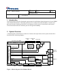
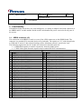
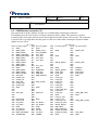
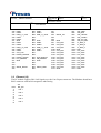
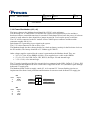
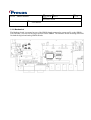
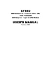
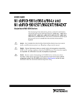
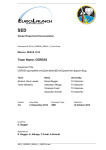
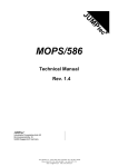
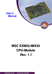
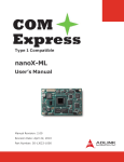
Date
FF019 – SBRIO Methone
Ref
2009-08-18 c002v1
Page
1(11)
Issued by
Jan-Erik Larsson
Title
User Manual
Methone Board
User Manual
Contents
1
Introduction ....................................................................................................................................... 2
2
System Overview .............................................................................................................................. 2
3
Functionality...................................................................................................................................... 3
3.1
3.2
3.3
3.4
3.5
3.6
3.7
3.8
3.8.1
3.8.2
3.9
3.10
3.11
SBRIO connector (J2)............................................................................................................................................ 3
COM Express connector (J1) ................................................................................................................................. 4
Ethernet (J5)........................................................................................................................................................... 5
USB (J6, J7, J8) ..................................................................................................................................................... 6
SATA (J12)........................................................................................................................................................... 7
VGA (J14)............................................................................................................................................................. 7
LVDS (J11)........................................................................................................................................................... 7
Super I/O................................................................................................................................................................ 7
Dual RS232 serial (J22, J23) ...................................................................................................................... 8
Keyboard and Mouse (J10) ......................................................................................................................... 8
Sound (J21) ........................................................................................................................................................... 9
Power Distribution (J19, J4) ................................................................................................................................ 10
Mechanical........................................................................................................................................................... 11
Date
FF019 – SBRIO Methone
Ref
Page
2009-08-18 c002v1
2(11)
Issued by
Jan-Erik Larsson
Title
User Manual
1 Introduction
This document describes the functional requirements for the Methone board designed to fit on a SBRIO
from National Instruments. The board will house a PC module from either Kontron or Toradex and
have the necessary connectors for the PC environment as well as power conversion for the system.
This document describes the function, pin-outs and general handling.
2 System Overview
A block diagram of the hardware is shown in. It shows the major blocks of the system which will be
described in the following chapters.
Power in Power out
Line in/out
12V
20V
3,3V DIO, max 10Mps
DIO SBRIO Conn
Beep
DC/DC
RST,BAT
COM Express Type 1
GPIO/SDIO (4r/4w)
HD
Audio
12V, Reset, PWR
5V
AC_SD
3,3V
Gigabit
Ethernet
Beeper
Ethernet
2
USB x 6
IEEE1284
LPC bus
LVDS
Super I/O
Controller
2
MAX206
SATA
2
VGA
SATA
JILI
Key/Mouse
Figure 1: Block diagram of the Methone Board.
RS232 x2
USB x 6
Date
FF019 – SBRIO Methone
Ref
Page
2009-08-18 c002v1
3(11)
Issued by
Jan-Erik Larsson
Title
User Manual
3 Functionality
The Methone board doesn’t have any own intelligence; it’s mainly an adapter board with connectors to
the SBRIO and PC module and the outside world it also handles the power conversion for all parts of
the system.
3.1 SBRIO connector (J2)
The connection to the SBRIO is made over one of the 4 DIO connectors on the SBRIO board. The
connector is a standard 2.54 mm pitch dual row 50 pin header. The signals are 3.3V with clamp diodes
to GND and 5V and a 33 ohm current-limiting posistor. Maximum current is specified to 3mA.
The following signals from the PC module are connected to the DIO connector:
• 8 GPIO/SDIO signals (4 in and 4 out) directly from the COM Express.
• 17 IEEE1284 signals from the superI/O chip to enable EPP/ECP communication.
J2
1
2
3
4
5
6
7
8
9
10
11
12
13
14
15
16
17
18
19
20
21
22
23
24
25
GND
LPT_ERR# (Port5 DIOCTL)
LTP_PD_0 (Port5 DIO0)
N/C
(Port5 DIO9)
LTP_PD_1 (Port5 DIO1)
N/C
(5V from SBRIO)
LTP_PD_2 (Port5 DIO2)
GND
LTP_PD_3 (Port5 DIO3)
N/C
(5V from SBRIO)
LTP_PD_4 (Port5 DIO4)
GND
LTP_PD_5 (Port5 DIO5)
GND
LTP_PD_6 (Port5 DIO6)
GND
LTP_PD_7 (Port5 DIO7)
GND
N/C
(Port5 DIO8)
GND
LPT_SLCT (Port6 DIO9)
LPT_PE
(Port6 DIOCTL)
GPO0
(Port6 DIO0)
GND
GPO1
(Port6 DIO1)
26
27
28
29
30
31
32
33
34
35
36
37
38
39
40
41
42
43
44
45
46
47
48
49
50
GND
GPO2
GND
GPO3
GND
LPT_AFD#
GND
LPT_SLIN#
GND
LPT_STB#
GND
LPT_INIT#
GND
LPT_BUSY
GND
GPI0
GND
GPI1
GND
GPI2
GND
GPI3
GND
LPT_ACK#
GND
(Port6 DIO2)
(Port6 DIO3)
(Port6 DIO4)
(Port6 DIO5)
(Port6 DIO6)
(Port6 DIO7)
(Port6 DIO8)
(Port2 DIO4)
(Port2 DIO5)
(Port2 DIO6)
(Port2 DIO7)
(Port2 DIO8)
Date
FF019 – SBRIO Methone
Ref
2009-08-18 c002v1
Page
4(11)
Issued by
Jan-Erik Larsson
Title
User Manual
3.2 COM Express connector (J1)
The connection to the PC Module is made over a standardized COM Express interface.
The Methone uses the first of the two 220-pin connectors (Row A&B). The connector is surface
mounted with 0.5mm pitch and selected so the height between the boards will be 8 mm. The connector
is specified for very high data rates and great care has to be taken when creating the layout to handle
signals of up to 3Gb/s.
Pin#
A1
A2
A3
A4
A5
A6
A7
A8
A9
A10
A11
A12
A13
A14
A15
A16
A17
A18
A19
A20
A21
A22
A23
A24
A25
A26
A27
A28
A29
A30
A31
A32
A33
A34
A35
J1 (1-55)
PC mod_signal
Pin#
B1
GND
GBE0_MDI3B2
GBE0_MDI3+
B3
B4
GBE0_LINK100#
GBE0_LINK1000#
B5
B6
GBE0_MDI2GBE0_MDI2+
B7
GBE0_LINK#
B8
B9
GBE0_MDI1GBE0_MDI1+
B10
B11
GND
GBE0_MDI0B12
GBE0_MDI0+
B13
GBE0_CTREF
B14
B15
SUS_S3#
SATA0_TX+
B16
B17
SATA0_TXSUS_S4#
B18
SATA0_RX+
B19
B20
SATA0_RXGND
B21
B22
B23
SUS_S5#
B24
B25
B26
BATLOW#
B27
ATA_ACT#
B28
AC_SYNC
B29
AC_RST#
B30
GND
B31
AC_BITCLK
B32
AC_SDOUT
B33
BIOS_DISABLE#
B34
B35
THRMTRIP#
PC mod_signal
GND
GBE0_ACT#
LPC_FRAME#
LPC_AD0
LPC_AD1
LPC_AD2
LPC_AD3
LPC_CLK
GND
PWRBTN#
SMB_CK
SMB_DAT
SMB_ALERT#
SUS_STAT#
GND
PWR_OK
WDT
AC_SDIN1
AC_SDIN0
GND
SPKR
I2C_CK
I2C_DAT
THRM#
Pin#
A56
A57
A58
A59
A60
A61
A62
A63
A64
A65
A66
A67
A68
A69
A70
A71
A72
A73
A74
A75
A76
A77
A78
A79
A80
A81
A82
A83
A84
A85
A86
A87
A88
A89
A90
J1 (56-110)
PC mod_signal
Pin# PC mod_signal
B56
GND
B57 SDIO0_WP
B58
B59
GND
B60 GND
B61
B62
SDIO0_DATA1
B63 SDIO0_CD#
B64
B65
GND
B66 WAKE0#
SDIO0_DATA2
B67 WAKE1#
PCIE_TX0+
B68 PCIE_RX0+
PCIE_TX0B69 PCIE_RX0GND
B70 GND
LVDS_A0+
B71
LVDS_A0B72
LVDS_A1+
B73
LVDS_A1B74
LVDS_A2+
B75
LVDS_A2B76
LVDS_VDD_EN
B77
LVDS_A3+
B78
LVDS_A3B79 LVDS_BKLT_EN
GND
B80 GND
LVDS_A_CK+
B81
LVDS_A_CKB82
LVDS_I2C_CK
B83 LVDS_BKLT_CTRL
LVDS_I2C_DAT
B84
SDIO0_DATA3
B85
KBD_RST#
B86
KBD_A20GATE
B87
PCIE0_CK_REF+
B88
PCIE0_CK_REFB89 VGA_RED
GND
B90 GND
Date
FF019 – SBRIO Methone
Ref
Page
2009-08-18 c002v1
5(11)
Issued by
Jan-Erik Larsson
Title
User Manual
A36
A37
A38
A39
A40
A41
A42
A43
A44
A45
A46
A47
A48
A49
A50
A51
A52
A53
A54
A55
USB6
USB6+
USB_6_7_OC#
USB4USB4+
GND
USB2USB2+
USB_2_3_OC#
USB0USB0+
VCC_RTC
EXCD0_PERST#
EXCD0_CPPE#
LPC_SERIRQ
GND
SDIO0_DATA0
B36
B37
B38
B39
B40
B41
B42
B43
B44
B45
B46
B47
B48
B49
B50
B51
B52
B53
B54
B55
USB7USB7+
USB_4_5_OC#
GND
USB3USB3+
USB_0_1_OC#
USB1USB1+
SYS_RESET#
CB_RESET#
GND
SDIO0_CMD
A91
A92
A93
A94
A95
A96
A97
A98
A99
A100
A101
A102
A103
A104
A105
A106
A107
A108
A109
A110
SDIO0_CLK
GND
VCC_Main
VCC_Main
VCC_Main
GND
VCC_Main
VCC_Main
VCC_Main
VCC_Main
VCC_Main
VCC_Main
VCC_Main
VCC_Main
VCC_Main
GND
B91
B92
B93
B94
B95
B96
B97
B98
B99
B100
B101
B102
B103
B104
B105
B106
B107
B108
B109
B110
VGA_GRN
VGA_BLU
VGA_HSYNC
VGA_VSYNC
VGA_I2C_CK
VGA_I2C_DAT
TV_DAC_A
TV_DAC_B
TV_DAC_C
GND
VCC_Main
VCC_Main
VCC_Main
VCC_Main
VCC_Main
VCC_Main
VCC_Main
VCC_Main
VCC_Main
GND
3.3 Ethernet (J5)
The PC module supplies Gbit LAN signals over the Com Express connector. The Methone board has a
RJ45 connector with built-in magnetics and filtering.
Pin#
1
2
3
4
5
6
7
8
J5
Diff_pair
Pair 1
Pair 2
Pair 3
Pair 2
Pair 4
Date
FF019 – SBRIO Methone
Ref
2009-08-18 c002v1
Page
6(11)
Issued by
Jan-Erik Larsson
Title
User Manual
3.4 USB (J6, J7, J8)
The PC module supplies USB 2.0 signals over the Com Express connector. The Methone board has
three double USB type A connectors for the USB signals as well as power supply with over-current
protection and signaling. Note that for Toradex modules USB channels 4 and 6 (J8) are Hi-speed (480
Mbit) only.
J6
Signal
Pin#
USB0
+5V
U1
U2 USB0 DU3 USB0 D+
U4 GND
L1 USB1 +5V
L2 USB1 DL3 USB1 D+
L4 GND
J7
Pin#
Signal
U1 USB2 +5V
U2 USB2 DU3 USB2 D+
U4 GND
L1 USB3 +5V
L2 USB3 DL3 USB3 D+
L4 GND
J8
Pin#
Signal
U1 USB4 +5V
U2 USB4 DU3 USB4 D+
U4 GND
L1 USB6 +5V
L2 USB6 DL3 USB6 D+
L4 GND
Note that the signal names above describe the connection to the Com Express connector, the actual
signal in the PC-module may vary depending on manufacturer.
For Toradex Robin module the signals are mapped as follows:
Com Exp.
USB0
USB1
USB2
USB3
USB4
USB6
PC-module
USB0
USB1
USB3
USB4
USB6
USB7
Remark
Hi-speed only (480 Mbit)
Hi-speed only (480 Mbit)
Date
FF019 – SBRIO Methone
Ref
2009-08-18 c002v1
Page
7(11)
Issued by
Jan-Erik Larsson
Title
User Manual
3.5 SATA (J12)
The PC module supplies SATA 1,5/3Gb/s signals over the Com Express connector. The Methone board
has one SATA data connector as well as a power connector J4 for 5V power limited to 1A for an
external 2.5” hard disk.
Pin#
1
2
3
4
5
6
7
J12
Signal
GND
Tx+
TxGND
Rx+
RxGND
J4
GND
+20V (SBRIO)
GND
+5V (SATA)
3.6 VGA (J14)
The PC module supplies VGA signals for an external monitor over the Com Express connector. The
Methone board has one 15-pin 3 row D-Sub for the signals.
Note that VGA is currently only supported by the Toradex module.
3.7 LVDS (J11)
The PC module supplies LVDS signals for an external LCD display over the Com Express connector.
This functionality is not supported on all PC modules. The Metjhone board has a 40 pin flat-foil
connector (FFC) to support the LVDS signals, power for electronics and backlight, control signals and
an I2C link for identification. The interface is referred to as JILI (Jumptec Intelligent LVDS Interface).
Note that this interface is only fully supported by the Kontron module and described in their
documentation.
3.8 Super I/O
The Methone board uses a Winbond W83627HF Super I/O chip to generate two RS232 ports, PS/2
signals for keyboard and mouse and IEE1284 signals for communication with the SBRIO over the DIO
interface. The Super I/O communicates with the PC module via the LPC (Low Pin Count) bus in the
Com Express connector.
Date
FF019 – SBRIO Methone
Ref
2009-08-18 c002v1
Page
8(11)
Issued by
Jan-Erik Larsson
Title
User Manual
Dual RS232 serial (J22, J23)
The Methone board has two RS232 channels with RXD/TXD, CTS/RTS, DSR/DTR and Ground in a
stacked double 9-pin D-Sub (plug). There is also +5V available on one pin in each D-sub. The total
current for the two pins together is limited to 1A
3.8.1
J22 (Com1)
Pin#
Signal
1
5V
2
TxD
3
RxD
4
DTR
5
GND
6
DSR
7
CTS
8
RTS
9
N/C
J23 (Com2)
Pin#
Signal
1
5V
2
TxD
3
RxD
4
DTR
5
GND
6
DSR
7
CTS
8
RTS
9
N/C
Keyboard and Mouse (J10)
The Super I/O has support for keyboard and mouse over PS/2.
3.8.2
The Methone layout supports both a double keyboard/mouse connector as well as combined signals for
both keyboard and mouse. The pin configuration of the lower connector is default for the keyboard and
if a mouse also needs to be attached a splitter cable has to be used. If a double connector is used the top
will be for mouse and have the corresponding mouse-signals and power connected.
J10 Keyboard/Mouse
Female connector from the front
Date
FF019 – SBRIO Methone
Ref
2009-08-18 c002v1
Page
9(11)
Issued by
Jan-Erik Larsson
Title
User Manual
Pin 1
+DATA (K) Data for Keyboard
Pin 2
+DATA (M) Data for Mouse*
Pin 3
GND
Ground
Pin 4
Vcc
+5 V DC at 100 mA
Pin 5
+CLK (K)
Clock for Keyboard
Pin 6
+CLK (M)
Clock for Mouse**
* Splitter cable is needed for Mouse data.
Pin also used in top connector for mouse.
** Splitter cable is needed for Mouse
clock. Pin also used in top connector for
mouse.
Figure 12: Keyboard/Mouse connector.
3.9 Sound (J21)
The Methone board has a Realtek ALC888 HDAudio Codec chip to handle audio. The line in /out are
connected to a pin header (J21) on the Methone board and it’s up to the user to do any adaption needed
for the system (amplifiers etc.) The Codec is connected to seven pins on COM Express connector
allocated to support HD Audio. There is also a beeper on the Methone board and it connects to the Com
Express as well as the Codec. The board also has a digital (SPDIF) output (J24).
J21
Pin#
Signal
1
Line_out_R
2
GND
3
Line_out_L
4
Line_in_R
5
GND
6
Line_in_L
Pin#
1
2
J24
Signal
Digital out
GND
Date
FF019 – SBRIO Methone
Ref
2009-08-18 c002v1
Page
10(11)
Issued by
Jan-Erik Larsson
Title
User Manual
3.10 Power Distribution (J19, J4)
The input voltage to the Methone board should be 12V DC at 6A minimum.
The incoming 12V is connected to J19 and the rail is short-circuit protected by a fuse and has a
hardware/software controlled transistor for on and off. Push button S2 activates the power (if software
control is used) otherwise there should be a jumper inserted in J3 to keep the power on all time.
The 12V will be connected to the PC module via the COM Express connector and the module
consumes roughly 6W (0,5A).
Push button S1 is generating a reset signal to the system.
The 12 V is also connected to J20 to drive a Fan.
The Methone board also has a battery holder for a back-up battery (mainly for the Real time clock on
the PC module). The battery should be a 3V Lithium type CR2032.
Other voltage supplies required for the system is generated on the Methone board. They are:
• 20V ±3% 1,0A for the SBRIO card (J4), to be supplied over a cable to the SBRIO.
• 5V ±5% 5,5A for USB, SATA, JILI, RS232, the Super I/O and internal logic.
• 3.3V ±5% 0,1A for internal logic.
The 5V supply is mainly provided for external devices connected to the USB, SATA (2.5” drive), JILI
Electronics (the Backlight needs more current and is supplied from the 12V) and RS232 ports through
dedicated 5V supply pins.
The Methone board is able to supply a total of 5 A for external 5V. Current limiting circuits are
implemented for short-circuit protection and limitation of current on each dedicated 5V supply pin.
Pin#
1
2
J19
Signal
GND
+12V in
Pin#
1
2
3
J20
Signal
N/C
+12V
GND
J4
GND
+5V (SATA)
GND
+20V (SBRIO)
Date
FF019 – SBRIO Methone
Ref
2009-08-18 c002v1
Page
11(11)
Issued by
Jan-Erik Larsson
Title
User Manual
3.11 Mechanical
The Methone board is mounted on top of the SBRIO board connected to connector P2 on the SBRIO.
The board has a cut-outs for the large capacitor on the SBRIO. The Methone board mounting stand-offs
fits both the digital and analog SBRIO boards.