1
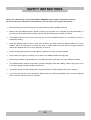
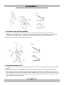
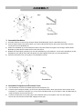
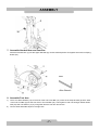
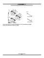
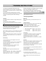
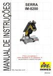
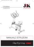
ELLIPTICAL TRAINER IMPORTANT: Read all instructions carefully before using this product. Retain this user’s manual for future reference. USER’S MANUAL TABLE OF CONTENT Safety Instructions ........…………………………………….. P. 2 Hardware Package .......... ………………………………….. P. 3 Assembly ......................... ................................................. P. 4 Computer Instructions ...... ................................................. P. 10 Training Instructions ......... ................................................. P. 12 Training Pulse Rate ......... ................................................. P. 13 Parts List ......................... ................................................. P. 14 Exploded Drawing ........... ................................................. P. 16 -1- SAFETY INSTRUCTIONS Before you start training on your E ELLIPTICAL TRAINER, please read the instructions carefully. Be sure to keep the instructions for information, in case of repair and for spare part delivery. Ø Read all instructions and warnings in this manual before using the elliptical trainer. Ø Before using this elliptical trainer, please consult your physician for a complete physical examination. If you feel any discomfort while exercising, please stop immediately and consult your doctor. Ø This elliptical trainer is for in-home use only; do not use the elliptical trainer in a commercial, rental, or institutional setting. Ø Keep the elliptical trainer indoors, away from moisture and dust. Place the elliptical trainer on a level surface, with a mat beneath it to protect the floor or carpet. Make sure that there is enough clearance around the elliptical trainer to mount, dismount, and use it. Ø Inspect and properly tighten all parts regularly. Replace any worn parts immediately. Ø Ensure that your fingers or clothing do not catch in the elliptical trainer moving parts. Ø Please keep children and pets away from the elliptical trainer at all times. It is only suitable for adults. Ø The elliptical trainer should not be used by persons weighting more than 150 kg. Serious injury may occur if the user’s weight exceeds the limit shown here. Ø To prevent injuring you when lifting and moving the machine, Please getting someone to help you. Ø If you hear unusual noise when exercising, please stop your training immediately. Do not use the elliptical trainer until the problem has been resolved. -2- HARDWARE PACKAGE This chart is provided to help you identify the hardware that may be unfamiliar to you. (#51) Arc Washer 4 PCS (#33) Screw Side Cover 2 PCS (#35) Spring Knob 2 PCS (#53) Washer 2 PCS (#54) Hex Socket Cap Bolt 4 PCS (#55) Cap Nut 4 PCS (#69) Nylon Nut 2 PCS (#70) Wave Washer 2 PCS (#71) Washer 2 PCS (#88) Allen Wrench 1 PC (#91) Hex Socket Cap Bolt 2 PCS (#94) Screwdriver 1 PC (#96) Cone Washer 4 PCS (#97) Arc Washer 4 PCS (#98) Screwdriver 1 PC (#50) Hex Socket Cap Bolt 4 PCS -3- ASSEMBLY Tool: Allen Wrench Screwdriver 1. Assemble Front and Rear Stabilizer 1) Identify the Front Stabilizer (2). While another person lifts the front of Main Frame (1), attach the Front Stabilizer (2) to the Main Frame (1) with two Hex Socket Cap Bolts (50), two Arc Washers (51) and two Cap Nuts (55). Use the Allen Wrench and Screwdriver to tighten the Cap Nuts (55) until firm and secure. 2) Do the same assemble steps to the Rear Stabilizer (3). Tool: Allen Wrench Screwdriver 2. Assemble Handlebar Post 1) Use Allen Wrench to remove two Hexagon Socket Head Bolts (52) and two Spring Washers (92) from Handlebar Post (4). 2) While another person holds the Handlebar Post (4) near the Main Frame (1), connect the Upper Computer cable (12) to the Lower Computer cable (13). Slide the Handlebar Post (4) into the Frame (1). Be careful not to pinch the cables. Tighten it with two Hexagon Socket Head Bolts (52), two Hexagon Socket Head Bolts (91), two Spring Washers (92), four Cone Washers (96), four Arc Washers (97) and two Nylon Nuts (69) by Allen Wrench and Screwdriver until firm and secure. -4- ASSEMBLY Tool: Allen Wrench Screwdriver 3. Assemble Handlebar 1) Use Allen Wrench to remove two Hexagon Socket Head Bolts (85) from the Handlebar Post (4). 2) Connect upper Hand Pulse Sensor Wire (17) to lower Hand Pulse Sensor Wire (18) at both sides. Hide the connection into the Handlebar (5). 3) Attach the Handlebar (5) to the metal parts under Computer bracket and tighten two Hexagon Socket Head Bolts (85) by Allen Wrench. Make sure it’s firm and secure. 4) Release four Self Tapping Screws (57) from the Handlebar (5) by Screwdriver. Cover end of Handlebar (5) with Handlebar Cover (30) at each side and tighten four Self Tapping Screws (57) by using Screwdriver. 5) Place the Decorate Cover (front) (26) on the Handlebar Post (4). Tool: Screwdriver 4. Assemble Computer and Decorate Cover 1) 2) 3) Use Screwdriver to remove four Bolts (58) from the Computer (11). Connect Upper Computer Cable (12) and Lower Hand Pulse Sensor Wires (18) with the wires at back of the Computer (11). Place the Computer (11) on top of the Handlebar Post (4), then tighten it with four Bolts (58) by using Screwdriver until firm and secure. Connect the Decorate Cover (rear) (26) to the Handlebar Post (4) and tighten it with one Self Tapping Screws (57) and two Round Head Self Tapping Screws (72). -5- ASSEMBLY Tool: Allen Wrench 5. Assemble Upper Handrail 1) Take off the End Caps (32) for the right Upper Handrail (6). 2) Insert the Upper Handrails (6) onto both sides of the axis on the Handlebar Post (4). Attach Screw Side Covers (33) behind them. Tighten them with two Hexagon Socket Head Bolts (54) and two Washers (53) by using Allen Wrench until firm and secure. Then replace the end cap (32). Tool: Screwdriver 6. Assemble Front Foot Bar Cover 1) Use Screwdriver to remove four Self-Tapping Screws (57) and two Round Head Self Tapping Screws (90) from the front of Foot Bar (9). 2) Cover the Foot Bar (9) with Front Foot Bar Cover (38) each side and tighten them with four Self-Tapping Screws (57) and two Round Head Self Tapping Screws (90). -6- ASSEMBLY 7. Assemble Handrail Arm and Foot Bar Insert the Handrail Arm (7) into the Upper Handrail (6), choose desired position and tighten them with two Spring Knobs (35). Tool: Allen Wrench 8. Assemble Foot Arm 1) 2) Place one Wave Washer (70) on the axis of the Left Cross Bar (10). Insert the U shape bracket (8) at the back of the Left Foot Bar (9) into the axis of the Left Cross Bar (10). Then tighten it with one Hexagon Socket Head Bolt (54) and one Washer (71) by using Allen Wrench until firm and secure. Do the same assemble steps for the right side. -7- ASSEMBLY Tool: Screwdriver 9. Assemble Rear Foot Bar Cover 1) 2) 3) Use Screwdriver to remove two Self Tapping Screws (57) at the back of the Left Foot Bar (9). Place the Rear Foot Bar Cover (39) around the Left U Shape Brackets (8). Tighten it with two Self Tapping Screws (57) by using Screwdriver. Do the same assemble steps for the right side. 10. Adaptor Installation. Plug one end of the Adaptor (87) into the power jack of the DC Cable (14) on the back of the Chain Cover. Before plugging in, make sure to check carefully the specifications on the Adaptor. Plug the other end of the Adaptor (87) into the electrical wall outlet. -8- ASSEMBLY Tool: Screwdriver Allen Wrench User can adjust Foot Pedal (22) position A or B, according to height. Now, your machine is ready for using. -9- COMPUTER INSTRUCTIONS BUTTON FUNCTION MODE In stop mode, the mode is to confirm all exercise data setting, and enter into program. RESET Return to the main menu in the STOP mode and clean all preset values to zero. START/STOP To start or stop exercise. RECOVERY To test hear rate recovery status. UP To select training mode and adjust function value up. DOWN To select training mode and adjust function value down. BODY FAT For body fat measurement DISPLAY EXERCISE DATA TIME Display range 0:00~99:99 ; Setting range 0:00~99:00 DISTANCE Display range 0.00~99.99 ; Setting range 0~99.90km CALORIES Display range 0~9999 ; Setting range 0.00~9990 PULSE Display range P-30~230 ; Setting range 0-30~230 WATT Display range 0~999 ; Setting range 10~350 SPEED Display current training speed from 0.0 to maximum 99.9 km or ml RPM Display current training rotation per minute. Display range 0~999 OPERATION PROCEDURE 1. Connect power supply and computer will power on with a long beep sound, LCD display all segments (drawing A) for 2 seconds and enter into personal data setting mode (gender, age, height and weight) for U1~U4. (drawing B) 2. After user data set up, computer will display main menu. 3. A B In main menu, first exercise program MANUAL will flash, user may press UP and DOWN button to select MANUAL àPROGRAM (12 profiles) à USER PROGRAMàH.R.CàWATT. 4. Quick Start and Manual : Before exercise in Manual mode, user my set up TIME, DISTANCE, CALORIES and PULSE target. After power on, user may press START/STOP button to start exercise in MANUAL immediately without any setting. Level can be adjusted during exercise by press UP or DOWN. 5. PROGRAM Before exercise in Program mode, user may set up TIME target. Press UP and DOWN to select Program with 12 profiles and press MODE to confirm. Level can be adjusted during exercise by press UP or DOWN. COMPUTER -INSTRUCTIONS 10 6. H.R.C. Select the H.R.C. mode and press the MODE key to enter into the setting mode. There will be 4 selections: H.R.C55, H.R.C.75, H.R.C.90 and H.R.C. TAG; use the UP/ DOWN key to select one program and press the MODE key after selection is determined. User’s selection and a sign of “55%” will be displayed in the PULSE column according to the AGE user inserted. If user selects H.R.C. TAG (press the MODE key to enter), preset PULSE value “100” will be shown in flashing text and user can press the UP/ DOWN key to adjust target range from 30~230. 7. USER PROGRAM User may press UP, DOWN and then press MODE to create his own profile. (From column 1 to column 20) User may hold on pressing MODE button for 2 seconds to quit profile setting. 8. WATT : The preset watt value 120 is flashing on screen in WATT setting mode. User may use UP, DOWN button to set target value from 10 to 350. Press MODE button for confirm. 9. BODY FAT: 9-1 In STOP mode, press the BODY FAT button to start body fat measuremen. 9-2 During measuring, user have to hold both hands on the handgrip. And the LCD will display “--” “--“ for 8 seconds until computer finish measuring. 9-3 LCD will display BODY FAT advice symbol, BODY FAT percentage, BMI for 30 seconds. 10. RECOVERY: After exercising for a period of time, keep holding on handgrips and press “RECOVERY” button. All function display will stop except “TIME” starts counting down from 00:60 to 00:00. Screen will display your heart rate recovery status with the F1, F2….to F6. F1 is the best, F6 is the worst. User may keep exercising to improve the heart rate recovery status. (Press the RECOVERY button again to return the main display.) NOTE: 1. This computer requires 9V, 0.5mA adaptor. 2. When user stop pedaling for 4 minutes, computer will enter into power save mode, all setting and exercise data will stored until user start exercise again. 3. When computer act abnormal, please plug out the adaptor and plug in again. TRAINING INSTRUCTIONS - 11 To achieve a considerable improvement of your physical resistance and your health, some aspects of how to find the most efficient amount of training should be followed: If you have not been physically active for a longer period of time and also to avoid health risks, you should consult your general physician before starting to exercise. During the first week, it is advisable to start with a pulse rate of 101. Afterwards, increase it to 117. With increasing improvement of fitness, the training intensity should be increased to 70% - 85% of your maximum pulse rate. Increasing the resistance, a higher frequency or longer training periods can do this. - 12 - Training Organization Intensity To achieve maximum results, the right intensity has to be chosen. The heart rate is used as guideline. As a rule of thumb the following formula is commonly used: Maximum pulse rate = 220 - Age While exercising, the pulse rate should always be between 60% - 85% of the maximum pulse rate. For your personal training rates, please see the attached pulse rate chart on page 13. When starting to exercise, you should keep your rate at 60% of your maximum pulse rate in the first couple of weeks. With increasing improvement of fitness, the pulse rate should be slowly increased to 85% of your maximum pulse rate. Fat burning The body starts to burn fat at approx. 60% of the maximum pulse rate. To reach an optimum at burning rate, it is advisable to keep the pulse rate between 60% – 70% of the maximum pulse rate. The optimum training amount consists of three workouts per week 30 minutes each. Example: You are 52 years of age and would like to start exercising. Maximum pulse rate = 220 - 52(age) = 168 pulse/min Minimum pulse rate = 168 x 0.6 = 101 pulse/min Highest pulse rate = 168 x 0.7 = 117 pulse/min Warm-up: Before every training, you should warm-up for 5-10 minutes. Training session: During the actual training, a rate of 70% -85% of the maximum pulse rate should be chosen. The time-length of your training session can be calculated with the following rule of thumb: • • • daily training session: approx. 10 min. per unit 2-3 x per week: approx. 30 min. per unit 1-2 x per week: approx. 60 min. per unit Cool down: To introduce an effective cool-down of muscles and metabolism, the intensity should be drastically decreased during the last 5 – 10 minutes. Stretching is also helpful for the prevention of muscle aches. Success Even after a short period of regular exercises, you will notice that you constantly have to increase the resistance to reach your optimum pulse rate. The units will be continuously easier and you will feel a lot fitter during your normal day. For this achievement, you should motivate yourself to exercise regularly. Choose fixed hours for your training session and do not start training too aggressively. An old quote amongst sportsmen says: “The most difficult thing about training is to start it.” Wish you have a lot of fun and success with your trainer, TRAINING PULSE RATE The HEART RATE CHART is only for the customer reference. - 13 - - 18 - - 10 - PART LIST No Description Q’ty No Description Q’ty 1 Main Frame 1 37 Handrail Arm Cover (pair) 2 2 Front Stabilizer Ø76x1.5T 1 38 Front Foot Bar Cover (pair) 2 3 Rear Stabilizer Ø76x1.5T 1 39 Rear Foot Bar Cover (pair) 2 4 Handlebar Post Ø60x2.0T 1 40 Belt Wheel Ø260 1 5 Handlebar Ø25.4x1.5T 1 41 Protector for Flywheel 2 6 Upper Handrail (L&R) Ø28x1.5T 1 42 Decorate Cap Ø60 for Front Post 1 7 Handrail Arm Ø32x1.5T 2 43 Foam Grips Ø 25x3Tx1140mm 1 8 U Shape Bracket 2 44 Foam grips Ø 28x5Tx725mm 2 9 Foot Bar (L&R) Ø50x2.0T 1 45 Flywheel Ø268 1 10 Cross Bar (L&R) 20x40x2T 1 46 Steel Bearing R12 2 11 Computer 1 47 Bushing Ø16x Ø38 4 12 Upper Computer Cable L=850mm 1 48 Bushing Ø10x Ø32 4 13 Lower Computer Cable with Motor 1 49 Belt 443J6 1 14 DC Cable L=700mm 1 50 Hex Socket Cap Bolt M10x85mm 4 15 Tension Control Cable L=150mm 1 51 Arc washer Ø10x Ø26x2.0T 4 16 Hand Pulse Sensor 2 52 Hex Socket Cap Bolt M8x15mm 2 17 Upper Hand Pulse Sensor Wire (pair) L=550mm 1 53 Washer Ø8x Ø21x2.0T 2 18 Lower Hand Pulse Sensor Wire (pair) L=250mm 1 54 Hex Socket Cap Bolt M8x18mm 4 19 Bolt for Tension Control 1 55 Cap Nut M10 4 20 Front Stabilizer Cap Ø76 2 56 Screw for Hand Pulse Sensor 2 21 Rear Stabilizer Cap Ø76 2 57 Self-Tapping Screw M5x12mm 13 22 Foot Pedal (L&R) 1 58 Bolt for Computer 4 23 Chain Cover (L&R) 1 59 Round Head Self Tapping Screw M4x20mm 4 24 Disk 2 60 Round Head Self Tapping Screw M4x15mm 4 25 Cap for Disk 2 61 Socket Head Cap Screw M6x54mm 4 26 Decorate Cover for Handlebar Post (F&R) 1 62 Socket Head Cap Screw M6x12mm 4 27 Ring Ø60 1 63 Washer Ø6xØ14x1.0T 12 28 Decorate Cover for Front Post (L&R) 1 64 Nylon Nut M6 4 29 Handrail End Cap Ø50 2 65 Hex Socket Cap Bolt M10x72mm 2 30 Handlebar Cover (pair) 2 66 Nylon Nut M10 2 31 Handrail Cover (pair) 2 67 Washer Ø10xØ19x1.5T 4 32 End cap for Axis of Handlebar Post 2 68 Hex Socket Cap Bolt M8x64mm 2 33 Screw Side Cover 2 69 Nylon Nut M8 4 34 Bushing Ø19x Ø 35 (Handrail Arm) 4 70 Wave Washer Ø16.2xØ25x0.5T 2 35 Spring Knob M16*22mm 2 71 Washer Ø8.5xØ30x2.0T 2 36 Fastener Ø25xØ32x88mm 2 - 14 - PART LIST No Description Q’ty No Description Q’ty 72 Round Head Self Tapping Screw M4.5x25mm 12 86 Washer Ø8.5xØ20x2.0T 4 73 Thread Cutting Screw M5x15mm 10 87 Adaptor 1 74 Belt Adjuster 2 88 Allen Wrench 5mm 1 75 Decorate Cap 30x60mm 1 89 Sensor Bracket 1 76 Washer Ø10xØ20x3.0T 2 90 Round Head Self Tapping Screw M4.5x15mm 2 77 C-ring Ø19mm 1 91 Hex Socket Cap Bolt M8x72mm 2 78 Hex Head Cap Bolt 3/8" 2 92 Spring Washer Ø8mm 2 79 Mushroom Head Screw M5x15mm 8 93 Washer Ø8xØ16x1.5T 2 80 Washer Ø19xØ25x3.0T 2 94 Screwdriver 10.14.17mm 1 81 Washer Ø19xØ25x0.5T 1 95 Magnet 1 82 Washer Ø19xØ25x2.0T 1 96 Cone Washer Ø8.15xØ11x3.5T 4 83 Mushroom Head Screw M5*12mm 1 97 Arc Washer Ø8xØ21x2.0T 4 84 Hex Nut 3/8"x9.0T 2 98 Screwdriver 10.13mm 1 85 Hex Socket Cap Bolt M8x38mm 2 - 15 - EXPLODED DRAWING - 16 -