1
O2 Graph
User Manual
Release 5.0 - April 1998
Information in this document is subject to change without notice
and should not be construed as a commitment by
O2 Technology.
The software described in this document is delivered under a
license or nondisclosure agreement.
The software can only be used or copied in accordance with the
terms of the agreement. It is against the law to copy this software
to magnetic tape, disk, or any other medium for any purpose
other than the purchaser’s own use.
Copyright 1992-1998 O2 Technology.
All rights reserved. No part of this publication can be
reproduced, stored in a retrieval system or transmitted in any
form or by any means, electronic, mechanical, photocopy without
prior written permission of O2 Technology.
O2, O2Engine API, O2C, O2DBAccess, O2Engine, O2Graph,
O2Kit, O2Look, O 2Store, O2Tools, and O2Web are registered
trademarks of O2 Technology.
SQL and AIX are registered trademarks of International
Business Machines Corporation.
Sun, SunOS, and SOLARIS are registered trademarks of Sun
Microsystems, Inc.
X Window System is a registered trademark of the
Massachusetts Institute of Technology.
Unix is a registered trademark of Unix System Laboratories, Inc.
HPUX is a registered trademark of Hewlett-Packard Company.
BOSX is a registered trademark of Bull S.A.
IRIX is a registered trademark of Siemens Nixdorf, A.G.
NeXTStep is a registered trademark of the NeXT Computer, Inc.
Purify, Quantify are registered trademarks of Pure Software Inc.
Windows is a registered trademark of Microsoft Corporation.
All other company or product names quoted are trademarks or
registered trademarks of their respective trademark holders.
Who should read this manual
Visualization of objects and their relations can enhance presentation.
This manual describes O2Graph, a graphical editor that links two or more
objects. Various O2Graph layouts are available: trees, grids, graphs, etc.
An O2Graph toolbox is provided with predefined classes: Graph, Node,
Link and GraphDialoguer.
Other documents available are outlined, click below.
See O2 Documentation set.
1
TABLE OF CONTENTS
This manual is divided into the following chapters:
1 - Introduction
2 - Data structures
3 - Presentation
4 - Layout managers
5 - Interactive behavior
6 - O2Kit toolbox for the Graph editor
O2Graph User Manual
5
TABLE OF CONTENTS
1
O2 Graph
9
1.1 System Overview......................................................................10
1.2 Introduction ..............................................................................12
1.3 The background .......................................................................12
2
Data Structures
15
3
Presentation and Display
19
3.1 Overview ...................................................................................20
3.2 General graph resources.........................................................21
4
Layout Managers
27
4.1 The grid layout manager..........................................................28
4.2 The tree layout manager .........................................................29
4.3 The isi layout manager ...........................................................32
4.4 The spring layout manager ...................................................34
5
Interactive Behavior
37
6
O2Kit Toolbox Features for the Graph Editor
41
6.1 The class graph ........................................................................42
6.2 The class Node .........................................................................44
6.3 The class Link...........................................................................45
6.4 The class GraphDialoger .........................................................46
6.5 Programming example using GraphDialoger ........................53
INDEX
6
59
O2Graph User Manual
1
O2 Graph
1
This manual explains how to use O2 Graph in order to display your
database objects in a graph.
This chapter is divided into the following sections:
•
System Overview
• Introduction
• The background
O2Graph User Manual
9
1
O2 Graph
1.1 System Overview
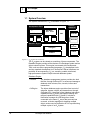
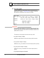
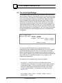
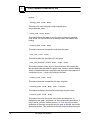
The system architecture of O2 is illustrated in Figure 1.1.
External
Interfaces
Development Tools
O2 Dev. Tools
Standard
Dev. Tools
O2 Graph
C
OQL
O2 C
C++
Java
Database Engine
O2Engine
O2Store
O2ODBC
O2Corba
O2DB
Access
O2Web
Fi gu r e 1 .1 : O2 Sy st em Ar ch i t ect u r e
The O2 system can be viewed as consisting of three components. The
Database Engine provides all the features of a Database system and an
object-oriented system. This engine is accessed with Development
Tools, such as various programming languages, O2 development tools
and any standard development tool. Numerous External Interfaces are
provided. All encompassing, O2 is a versatile, portable, distributed,
high-performance dynamic object-oriented database system.
Database Engine:
10
• O2Store
The database management system provides low level
facilities, through O2Store API, to access and manage a
database: disk volumes, files, records, indices and
transactions.
• O2Engine
The object database engine provides direct control of
schemas, classes, objects and transactions, through
O2Engine API. It provides full text indexing and search
capabilities with O2Search and spatial indexing and
retrieval capabilities with O2Spatial. It includes a
Notification manager for informing other clients
connected to the same O2 server that an event has
occurred, a Version manager for handling multiple
object versions and a Replication API for synchronizing
multiple copies of an O2 system.
O2Graph User Manual
System Overview
:
Programming Languages:
O2 objects may be created and managed using the following
programming languages, utilizing all the features available with O2
(persistence, collection management, transaction management, OQL
queries, etc.)
• C
O2 functions can be invoked by C programs.
• C++
ODMG compliant C++ binding.
• Java
ODMG compliant Java binding.
• O2C
A powerful and elegant object-oriented fourth
generation language specialized for easy development
of object database applications.
• OQL
ODMG standard, easy-to-use SQL-like object query
language with special features for dealing with complex
O2 objects and methods.
O2 Development Tools:
• O2Graph
Create, modify and edit any type of object graph.
• O2Look
Design and develop graphical user interfaces, provides
interactive manipulation of complex and multimedia
objects.
• O2Kit
Library of predefined classes and methods for faster
development of user applications.
• O2Tools
Complete graphical programming environment to
design and develop O2 database applications.
Standard Development Tools:
All standard programming languages can be used with standard
environments (e.g. Visual C++, Sun Sparcworks).
External Interfaces:
• O2Corba
Create an O2/Orbix server to access an O2 database
with CORBA.
• O2DBAccess Connect O2 applications to relational databases on
remote hosts and invoke SQL statements.
• O2ODBC
Connect remote ODBC client applications to O2
databases.
• O2Web
Create an O2 World Wide Web server to access an O2
database through the internet network.
O2Graph User Manual
11
1
O2 Graph
1.2 Introduction
A graph editor is any graphic display that connects two or more objects
with links. It can be used with different layout policies to represent trees,
graphs, networks, etc. Certain interactive manipulations are allowed on a
graph editor.
O2Graph provides a specific editor called graph which may be invoked to
perform these functions. The graph editor is a mask that may be used to
display an O2 value of a particular structure; the value specifies the set of
nodes of the graph, as well as the set of links that connect the nodes.
Additional information (background of the graph, position of each node
against the background, content of each node, shape of each link,
optional label for each link, scale) may also be given in the value. If
permission is granted, the user may move nodes, insert new nodes,
insert new links, remove nodes, and remove or redraw links.
1.3 The background
The background display of a graph editor may be a bitmap image (black
and white) or a pixmap image (color), or nothing at all. The schema
presented in the section below defines the background as a Drawable.
This O2 class is defined in the o2kit schema. Two sub-classes of
Drawable are also defined: the Bitmap class and the Image class. A
method is defined for these two classes to initialize objects with bitmaps
or images.
This method is named loadfile. The loadfile method takes one
parameter and is invoked as:.
• drawable->loadfile (unixfile);
where:
• drawable is an instance of the class Bitmap or the class Image.
• unixfile is a Unix path to an X11 bitmap file if drawable is an instance of
the class Bitmap, or to a GIF file if drawable is an instance of the class
Image.
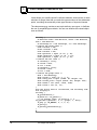
In order to use these classes in an O2 schema, you must import them
from the o2kit schema using the following syntax: o2kit:Schema
import schema o2kit class Drawable, Bitmap, Image; Once a
12
O2Graph User Manual
The background :
background has been defined, the nodes of the graph may be positioned
at particular points of the background. Each point is specified with
horizontal and vertical coordinates (x and y). These coordinates may be
chosen simply (that is, with the top left corner of the background being
coordinate (0, 0) and other values representing distances in screen
pixels from this point); or they may be expressed in more human-friendly
terms, such as centimeters, miles, or degrees of longitude and latitude.
In that case, a distinction is made between “screen size” and “real size”
(as explained in Chapter 2).
Alternatively, you can let the graph editor itself take the responsibility for
positioning the nodes. Four layout managers are available for this
purpose (Chapter 4). If a layout manager is used, the point coordinates
of each node are ignored (or realigned) and may be left unspecified.
O2Graph User Manual
13
1
14
O2 Graph
O2Graph User Manual
2
2
Data Structures
This chapter describes the various data used with the Graph editor.
O2 Graph User Manual
15
2
Data Structures
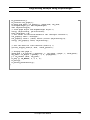
The graph editor may be used to display any O2 value whose type
conforms to the following tuple specification. (O2Kit contains a class with
this structure; refer to Chapter 6 : O2Kit Toolbox Features for the Graph
Editor):
type graph: tuple (origin:
tuple (x:
y:
real_size:
tuple (width:
height:
screen_size: tuple (width:
height:
background: Drawable,
nodes:
set (Node),
links:
set (Link));
integer,
integer),
integer,
integer),
integer,
integer),
This definition of the graph type refers to the following class definitions:
class Node
public type tuple (position:
content:
end;
class Link
public type tuple (drawing:
label:
from:
to:
tuple (x:
y:
<any>)
list(tuple (x:
y:
<any>,
Node,
Node)
integer,
integer),
integer,
integer)),
end;
The details on each of the attributes is as follows:
• origin.x: The horizontal offset of the background within a larger
frame of reference. This is the distance, in any horizontal unit of
measurement, from the x-axis of the larger frame to the left edge of the
background display. If there is no larger frame of reference, this may be
left zero.
• origin.y: The vertical offset of the background within a larger frame
of reference. This is the distance, in any vertical unit of measurement,
16
O2 Graph User Manual
:
from the y-axis of the larger frame to the top edge of the background
display. If there is no larger frame of reference, this may be left zero.
• real_size.width: The width of the background display, expressed in
the same units of horizontal measurement as used for x.
• real_size.height: The height of the background display, expressed
in the same units of vertical measurement as used for y.
• screen_size.width: The width of the background display — the
same as real_size.w, except expressed in pixels. The graph editor
uses this information to determine how to convert from the userdefined horizontal coordinates to pixels.
• screen_size.height: The height of the background display — the
same as real_size.h, except expressed in pixels. The graph editor
uses this information to determine how to convert from the userdefined vertical coordinates to pixels.
• background: The background of the graph display. This may be an
object of the class Bitmap or Image or one of their subclasses. If the
user does not want to have a background, nothing should be assigned
to this field.
The background specified here is used to tile the graph window
(whose size is specified in the fields above). Tiling is the laying out of a
background image to cover an area. The background image is applied
at the origin (top left corner) of the window. Another copy of the same
background image is applied next to the first one, and another below it,
and so on until the window is filled. This process fills the background of
the graph with many copy of the same image or bitmap. To have only
one representation of a bitmap or an image in the background of the
graph, the size of the background specified in this field should be the
same as the screen_size specified above.
• nodes: A set of objects of class Node. Each element represents a node
of the graph.
- position.x: The horizontal position of the node, with respect to
the overall frame of reference and in the same units of horizontal
measurement used in origin.x and real_size.width above.
- position.y: The vertical position of the node, with respect to the
overall frame of reference and in the same units of vertical
measurement used in origin.y and real_size.height above.
O2 Graph User Manual
17
2
Data Structures
- content: The O2 object to be presented in the node. An O2 value
may also be specified here. The object is presented in the node
according to the mask specified in the lk_specific function (see
Chapter 3 : Presentation and Display).
• links: A set of objects of class Link. Each element describes a link
between two nodes in the graph.
- drawing: A list of values of type point. The two nodes given in the
fields below are linked together with a polyline, described with this
list of points. This list may be left empty, in which case a simple line
is used to connect the two nodes. (This field is ignored if a layout
manager is used.)
x: The horizontal position of one end of the polyline, with respect
to the overall frame of reference and in the same units of horizontal measurement used in origin.x and real_size.width
above.
y: The vertical position of one end of the polyline, with respect to
the overall frame of reference and in the same units of vertical
measurement used in origin.y and real_size.height above.
- label: The O2 object or value to be used as a label for the link. An
O2 value may also be specified here. The label appears in the
middle of the link if the resource showLabel is set to true; if the
resource is set to false, this field is ignored.
- from: An object of class Node. This object must also appear in the
nodes field of the same graph value. This node represents the
starting point of the link.
- to: An object of class Node. This object must also appear in the
nodes field of the same graph value. This node represents the
ending point of the link.
Warning !
When designating an arc from a given node A to another node B, only
this link is then allowed. You cannot then designate on the same two
nodes an arc from node B to node A.
18
O2 Graph User Manual
3
3
Presentation and Display
This chapter describes how to define a presentation for your objects,
values, and so forth. It also details the various resources offered by the
Graph Editor for this presentation.
O2 Graph User Manual
19
3
Presentation and Display
3.1 Overview
A value of type graph may, of course, be displayed with the usual tuple
and list masks. In order to make use of the special features of a graph
value, however, a specific editor mask must be created using the
lk_specific mask function, as explained in the O2 Look Manual. For
the graph specific editor, lk_specific must be called as follows:
lk_specific (ed_name, rcount, resources, "graph", mcount, masks)
Such a graph mask may only be invoked upon a value whose structure
conforms to that described in Chapter 2. The arguments of the
lk_specific mask function are as follows:
• ed_name: A string representing the widget name of the mask. This
name may be used in a resource file to specify graphic resources for
this individual mask (refer to the O2 Look Manual).
• rcount: An integer count of the number of special resources given in
the resources argument.
• resources: A pointer to an array of graphic resources to be customized
in the mask (unless rcount is zero). Each resource in the array is of
type Lk_resource. For details on the specification of resources in this
way, refer to the O2 Look Manual. A list of resources for the graph
editor is given below.
• "graph": This is the name of the specific editor to create.
• mcount: the number of sub-masks used by this specific editor. This
should be either 1 (if link labels are not displayed) or 2 (if they are
displayed).
• masks: A pointer to an array of sub-masks (i.e. values of type Mask)
used in this specific editor. The number of masks in this array is
mcount. The first mask in the array will be used to display the content
of the nodes; the second (if any) is for the label of the links.
Note
When you define the presentation for an object of the class Graph, you
use the function lk_present. Please note that the background attribute
20
O2 Graph User Manual
General graph resources
is set to nil after lk_present and you must save the graph background
beforehand and restore it afterwards if you want to use the same
background. For example :
o2 Drawable d;
o2 Graph obj;
Lk_presentation p;
...
d=obj->background;
p=lk_present(obj, lk_object(0, 0,0,
lk_specific(0, 0, 0, ‘‘graph’’, 0, 0)));
obj->background=d;
3.2 General graph resources
The graph editor may use any of four different layout managers, or no
layout manager (in order to specify the coordinates of the nodes using
the position attributes). The layout policy is specified in the layout and
doLayout resources; the other graphic resources available to the
specific editor mask depend, in part, upon the layout policy used.
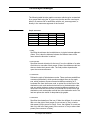
The following table lists the graphic resources which may be customized
for any graph mask, regardless of layout policy; these resources are
specified using the lk_specific function, either in a resource file in
association with the ed_name argument, or directly in the resources
argument of the function
Table 1.1
Graphic resources
Name
Type
Default
Access
arrowStyle
arrowHeight
arrowWidth
attachFrom
attachTo
autoLinkSelect
doLayout
hMargin
hSize
char
int
int
string
string
Boolean
Boolean
int
short
’’
12
6
center
center
True
False
10
0
CS
CS
CS
CS
CS
CS
CS
CS
CS
O2 Graph User Manual
21
3
Table 1.1
Presentation and Display
Graphic resources
Name
Type
Default
Access
hSizeMax
layout
linkColor
linkNewProcess
linkThickness
maxHeightVisible
maxWidthVisible
minHeight
minWidth
moveProcess
multiLinkProcess
nodeCutProcess
nodeNewProcess
replaceProcess
resizeProcess
selBorder
selColor
selectProcess
selThickness
showLabel
vMargin
vSize
vSizeMax
Boolean
string
Color
Boolean
short
short
short
short
short
Boolean
Boolean
Boolean
Boolean
Boolean
Boolean
Boolean
Color
Boolean
short
Boolean
int
short
Boolean
False
null
Dynamic
False
2
300
300
20
20
False
False
False
False
False
False
True
Dynamic
False
4
False
10
0
False
CS
C
CS
CS
CS
CS
CS
CS
CS
CS
CS
CS
CS
CS
CS
CS
CS
CS
CS
CS
CS
CS
CS
• arrowStyle
Specifies the graphical aspect of the arrows. If arrows are not wanted,
this resource should be set to the character ’ ’ (one blank); otherwise,
the character ’>’ should be used.
• arrowHeight
Specifies the length of arrows along the link direction, in pixels.
Typically, arrowHeight is twice arrowWidth.
• arrowWidth
Specifies the thickness of arrows (orthogonal to the link direction), in
pixels.
• attachFrom
22
O2 Graph User Manual
General graph resources :
Specifies where the starting point of links are attached to nodes. The
possibilities are:
- center (or default): Links join “underneath” the center of the node
(i.e. the node hides the ends of the links).
- top: Links join at the center of the top edge of the node.
- bottom: Links join at the center of the bottom edge of the node.
- left: Links join at the center of the left edge of the node.
- right: Links join at the center of the right edge of the node.
- top_left: Links join at the top left corner of the node.
- top_right: Links join at the top right corner of the node.
- bottom_left: Links join at the bottom left corner of the node.
- bottom_right: Links join at the bottom right corner of the node.
In all cases, a node will hide any part of a link that occupies the same
space as the node.
• attachTo
Specifies where the ending point of links are attached to nodes. The
possibilities are the same as for attachFrom, and the default is
center.
• autoLinkSelect
Determines whether links between selected nodes are automatically
selected. If true, selecting two nodes will automatically select any link
between them, independently of the explicit selection state defined by
the end user.
• doLayout
Specifies whether a layout manager should be invoked. If true, the
layout manager specified in the layout resource governs the
construction of the graph presentation. If false (or if the layout
resource is set to null), then no layout manager is used, and the
position of each node is determined by the value of the position
attribute of each object of class Node.
• hMargin
Specifies the horizontal distance, in pixels, from the left edge of the
graph presentation to the left edge of the leftmost node, and from the
right edge of the rightmost node to the right edge of the graph
O2 Graph User Manual
23
3
Presentation and Display
presentation.
• hSize
Specifies the width of all nodes (unless the hSizeMax resource is set
to true), in pixels. If zero (the default), each node will have its own
natural width (and they may all be different).
• hSizeMax
If set to true, all nodes have the same width, namely the current
maximum width of all the nodes of the graph. If set to false (the
default), the value of the hSize resource governs the node widths.
• layout
Specifies the layout manager to use, if the doLayout resource is set to
true. The possibilities are grid, tree, isi, spring, and null; each
is described in a separate subsection below. In addition, each layout
manager allows the specification of its own graphic resources, listed in
separate tables below. If the layout resource is null (the default),
then no layout manager is used, even if doLayout is set to true.
This resource can be set only at creation time.
• linkColor
Specifies the color of the lines used to draw the links.
• linkNewProcess
Determines whether the user can interactively add links between
nodes (using the ControlShift keys plus the right mouse button).
• linkThickness
Specifies the thickness (in pixels) of the lines used to draw the links.
• maxHeightVisible
Specifies the maximum visible vertical size, in pixels, of the graph. If
the vertical size of the graph is greater than this value, a vertical
scrollbar appears on the left side of the graph window.
• maxWidthVisible
Specifies the maximum visible horizontal size, in pixels, of the graph. If
the horizontal size of the graph is greater than this value, an horizontal
scrollbar appears at the bottom of the graph window.
24
O2 Graph User Manual
General graph resources :
• minHeight
Specifies the minimum height, in pixels, of the graph editor. The actual
height of the graph is dynamically changed to enclose all the nodes
plus the vertical margin (the vMargin resource). If this size is less
than the minimum height, then the minimum height is used instead.
• minWidth
Specifies the minimum width, in pixels, of the graph editor. The actual
width of the graph is dynamically changed to enclose all the nodes
plus the horizontal margin (the hMargin resource). If this size is less
than the minimum width, then the minimum width is used instead.
• moveProcess
Determines whether the user can interactively move nodes around
(using the Shift key plus the right mouse button).
• multiLinkProcess
Specifies whether user-added links may or may not be made up of
more than one line segment (i.e. jagged lines). If true, the user may
click several times during the construction of a link, and each click that
does not occur on a node will produce an “elbow” of the multi-segment
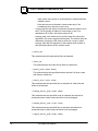
link. Figure 1.2 shows an example of a multi-segment link.
• nodeCutProcess
Specifies whether a cut operation (with the Control key plus the
middle mouse button) can be performed on the nodes of a graph
display. If set to True, the user may remove nodes from the graph.
• nodeNewProcess
Determines whether the user can interactively add nodes (using the
right mouse button).
• replaceProcess
Specifies whether the contents of a node icon can be replaced with an
O2Look paste operation.
• resizeProcess
Determines whether the user can interactively resize nodes (using the
Control key plus the right mouse button).
• selBorder
O2 Graph User Manual
25
3
Presentation and Display
Determines how to display selected nodes. If true, selected nodes are
surrounded by a rectangle, whose color and thickness are specified by
selColor and selThickness. If false, selected nodes have their
background color set to selColor.
• selColor
Specifies the color used to distinguish a selected node and link from
an unselected one.
• selectProcess
Determines whether the user can interactively select nodes and links
(using the middle mouse button).
• selThickness
Specifies the thickness, in pixels, of the selection outlines for the
selected links, and for the selected nodes when selBorder is true.
Selected links are drawn with two lines: one line using the linkColor
and linkThickness resources, and one line using the selColor and
selThickness resources. Depending on the relative values of
linkThickness and selThickness, the thickest line is drawn first.
• showLabel
Determines whether link labels are visible or not. If true, the link label
(as specified in the label attribute of instances of class Link) is
displayed superimposed upon the center of the link line.
• vMargin
Specifies the vertical distance, in pixels, from the top of the graph
presentation to the top edge of the topmost node, and from the bottom
edge of the bottom-most node to the bottom of the graph presentation.
• vSize
Specifies the height of all nodes (unless the vSizeMax resource is set
to true), in pixels. If zero (the default), each node will have its own
natural height (and they may all be different).
• vSizeMax
If set to true, all nodes have the same height, namely the current
maximum height of all the nodes of the graph. If set to false (the default),
the value of the vSize resource governs the node heights.
26
O2 Graph User Manual
4
4
Layout Managers
This chapter offers some guidelines as to the overall layout possible with
the GraphEditor and its various managers.
The chapter is divided into the following sections :
• The grid layout manager
• The tree layout manager
• The isi layout manager
• The spring layout manager
O2 Graph User Manual
27
4
Layout Managers
4.1 The grid layout manager
The grid layout manager is a simple layout manager for the graph
editor. It forces all nodes of the graph to occupy slots on a fixed
rectangular grid, whose characteristics are determined by specific
resources. This layout manager is useful when the exact position of the
nodes is not important, but neatness is. If the position of a node is
specified (in the position attribute), the grid layout manager places the
node at the slot on the grid closest to the specified coordinates (without
bothering to check if a node already occupies that slot). If no position is
specified (that is, if the coordinates are both zero), then the manager
assigns it to the first free slot that it finds. When a node is moved, the
manager snaps the node into the slot closest to where the user dropped
it, regardless of whether that slot is already occupied. The grid layout
manager thus allows nodes to overlap, partially or totally.
The following table lists the graphic resources which may be customized
for a graph mask using the lk_specific function and the grid layout
manager, either in a resource file in association with the ed_name
argument, or directly in the resources argument of the function :
Table 1.2
Corresponding O2 and IDL types for export
Name
Type
Default
Access
hGrid
hOrigin
horizontal
maxInRow
vGrid
vOrigin
int
int
Boolean
int
int
int
80
80
True
5
40
40
CS
CS
CS
CS
CS
CS
• hGrid
Specifies the horizontal separation, in pixels, between the centers of
adjacent nodes.
• hOrigin
Specifies the horizontal coordinate of the center of the first node in
each row. This is the distance, in pixels, from the left edge of the
display.
28
O2 Graph User Manual
The tree layout manager
• horizontal
Specifies the main direction for the grid. If true, rows are filled one
after another; a new row is started when the current row has
maxInRow nodes. If horizontal is false, columns are filled one after
another; a new column is started when the current column has
maxInRow nodes.
• maxInRow
Specifies the maximum number of nodes per row (if the horizontal
resource is true) or per column (if horizontal is false).
• vGrid
Specifies the vertical separation, in pixels, between the centers of
adjacent nodes.
• vOrigin
Specifies the vertical coordinate of the center of the first node in each
column. This is the distance, in pixels, from the top edge of the display.
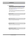
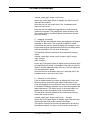
4.2 The tree layout manager
The tree layout manager is specialized in the display of hierarchical
tree structures. A graph presentation using the tree layout manager is
shown in Figure 1.1, The tree layout manager. Note that each node on
the tree may be the destination of at most one link (the to attribute of the
class Link), although it may be the source (the from attribute) of any
number of links.The tree layout manager assumes that the
O2 Graph User Manual
29
4
Layout Managers
Figure 1. 2:The tree layout manager
links represented in the graph value conform to hierarchical rules (that
is, no node may be the destination of more than one link). If this is not the
case, the layout manager extracts a “forest” of trees out of the data
anyway, using the following simple rules:
• If a node is not the destination of any link, it is the root of a tree.
• If a node is the destination of exactly one link, the source node of that
link is the parent of this node.
• If a node is the destination of several links, all links but one are ignored
(randomly), and the source node of the remaining link is the parent of
this node.
The tree, or trees, that result from this selection are displayed according
to some aesthetic principles:
• Nodes at the same level of the tree lie along a straight line. The lines
defining the different levels are parallel.
• A parent node is centered over its children.
• Nodes at the same level are separated by a minimum distance.
• A subtree is drawn the same way regardless of where it occurs in the
tree.
• The overall width of each tree is minimized.
• The trees of the forest are separated by a minimum distance.
•
The tree is dynamically reconfigured when nodes and links are added
and deleted. For instance, if a node A is the destination of two links from
nodes B and C, and if the link between A and C was ignored (according to
the rules above), then that link will be reinstated if the user should delete
the link between A and B. When a node is added to the graph and it is
not the root of a new tree, it is automatically placed as the last child of its
parent node.
30
O2 Graph User Manual
The tree layout manager
The following table lists the graphic resources which may be customized
for a graph mask using the lk_specific function and the tree layout,
either in a resource file in association with the ed_name argument, or
directly in the resources argument of the function.
Table 1.3
Graph resources
Name
Type
Default
Access
hGap
horizontal
linkClass
reversed
vGap
int
Boolean
string
Boolean
int
10
True
standard
False
25
CS
CS
CS
CS
CS
• hGap
Specifies the minimum horizontal distance, in pixels, between adjacent
nodes. This is also the distance between the different trees of the
forest when the direction is vertical.
• horizontal
Specifies the main direction for the tree. If true, the children of a node
are laid out on one side of their parent. If false, the children are laid out
above or below their parent node. The final position depends also
upon the reversed resource.
• linkClass
Defines the style of links between nodes. There are three possibilities:
standard (the default), which produces straight lines at any angle;
hvh, which produces square-cornered multilines consisting of a
horizontal line from the source node, a vertical line to the level of the
destination node, and another horizontal line to the destination node;
and vhv, which produces square-cornered multilines consisting of a
vertical line from the source node, a horizontal line to the level of the
destination node, and another vertical line to the destination node. The
last two options are useful for dropchart-style graphs.
• reversed
Specifies the orientation of the tree. If false, the children of a node are
laid out to the right of their parent (if horizontal is True) or below
their parent (if horizontal is False). If true, the children of a node are
laid out to the left of their parent (if horizontal is True) or above their
parent (if horizontal is False).
O2 Graph User Manual
31
4
Layout Managers
• vGap
Specifies the minimum vertical distance, in pixels, between nodes. This
is also the distance between the different trees of the forest when the
direction is horizontal.
4.3 The isi layout manager
The isi layout manager displays a direct acyclic graph or DAG. In a
DAG, a node can be the destination of any number of links (to attribute of
the class Link), or the source (from attribute) of any number of links.
However, links in a DAG cannot form cycles. The isi layout manager
extracts a DAG from the graph and displays it according to the layout ISI
Grapher algorithm.1 This algorithm lays out the x and y coordinates of
the nodes independently:
• The y coordinate of a node without children (a “leaf”) is set so the
nodes do not overlap vertically.
• The y coordinate of a non-leaf node is set to the average of the y
coordinates of its children.
• The x coordinate of a node without parents (a “root”) is set to 0.
• The x coordinate of a non-root node is set to the right of all of its
parents.
This is a very efficient layout manager. The time required for the layout
algorithm to operate is linearly proportional to the number of nodes plus
the number of links, making the isi manager very practical for large
graphs. If the graph is not a DAG (that is, if it has cycles), it is turned into
a DAG by arbitrarily ignoring one link per cycle for the sake of layout
construction. (Ignored links are still drawn.) The display is dynamically
reconfigured when nodes and links are added and deleted. For instance,
1. G. Robins, “The ISI Grapher: A Portable Tool for Displaying Graphs Pictorially”, ISI Reprint Series, USC/Information Science Institute, 4676 Admiralty
Way, Marina del Rey, CA 90292-6695, USA.
32
O2 Graph User Manual
The isi layout manager
if a link that was part of a cycle is deleted, the link that had been ignored
in order to break the cycle is once again taken into account.
The following table lists the graphic resources which may be customized
for a graph mask using the lk_specific function and the isi layout,
either in a resource file in association with the ed_name argument, or
directly in the resources argument of the function.
Table 1.4
Graphic resources
Name
Type
Default
Access
hGap
int
10
CS
horizontal
Boolean
True
CS
reversed
Boolean
False
CS
vGap
int
25
CS
• hGap
Specifies the minimum horizontal distance between nodes. If the layout
is horizontal, this is the minimum horizontal distance between a node
and its parents. If the layout is vertical, this is the minimum horizontal
distance between leaves.
• horizontal
Specifies the main direction for the DAG. If true, the children of a node
are laid out on one side of their parent. If false, the children are laid out
above or below their parent node. The final position depends also upon
the reversed resource.
• reversed
Specifies the orientation of the DAG. If false, the children of a node are
laid out to the right of their parent (if horizontal is True) or below their
parent (if horizontal is False). If true, the children of a node are laid out
to the left of their parent (if horizontal is True) or above their parent (if
horizontal is False).
• vGap
Specifies the minimum vertical distance between nodes. If the layout is
horizontal, this is the minimum vertical distance between leaves. If the
O2 Graph User Manual
33
4
Layout Managers
layout is vertical, this is the minimum vertical distance between a node
and its parents.
4.4 The spring layout manager
The spring layout manager uses a spring model to display an arbitrary
graph which is reshaped whenever a link or node is added, deleted or
moved. All other links or nodes move to compensate for a change and an
animation feature enables you to watch the process. The reshaping rules
are based on spring dynamics calculations.
A distance d is defined over the graph nodes: the distance between two
nodes is the shortest path length. Directly connected nodes have a
distance of 1, and nodes in different unconnected components have an
infinite distance. Each node pair with a finite distance d is linked by a
spring whose strength is proportional to 1/d2 .
The dynamic system of nodes and springs is stable when the distance
between each node pair is L times the graph-distance between the
nodes; L is the unit length and is specified in the length resource. When
the system is stable, its energy is zero. When the system is unstable, the
strengths of the springs determine a state with locally minimal energy.
The graph is brought to a minimal energy each time the graph is
changed. This is done by an incremental algorithm that takes each node
to a stable position one by one until the energy changes by less than an
epsilon between two algorithm iterations. This value is specified in the
epsilon resource. At each stage, the node with the highest energy is
moved.
The graph is dynamically reconfigured when nodes and links are added
and deleted. When a node is moved or created, that node is pinned to
where you placed it, and the other nodes move around it.1 The animation
feature that displays the successive states of the resolution as feedback.
You can therefore easily follow layout modifications. It is also valuable
when the graph is large and the reshaping takes a long time.
The following table lists the graphic resources for a graph mask using
the lk_specific function and the spring layout, either in a resource file
1. If this were not the case, the node just moved would be the one with the highest energy, and would simply be tugged back to its initial position straight
away.
34
O2 Graph User Manual
The spring layout manager
in association with the ed_name argument, or directly in the resources
argument.
Table 1.5
Graphic resources
Name
Type
Default
Access
animate
epsilon
length
maxIter
maxLoop
int
int
int
int
int
10
10
75
25
10
CS
CS
CS
CS
CS
• animate
Specifies algorithm animation. If 0, none occurs. If positive, a graph
outline is displayed at each algorithm step. The value specifies the
number of steps and level of animation detail: if a node is moved by more
than animate pixels, the move is decomposed into a number of
submoves each of animate pixels.
• epsilon
Specifies minimum variation of graph energy between two iterations
below which the algorithm stops. A small epsilon gives better results but
is longer to obtain.
• length
Specifies unit link length (value L) in pixels. The algorithm tries to make
all links this long. Raising or lowering this value loosens or tightens the
springs controlling the layout.
• maxIter
Specifies maximum number of iterations for a single node. At each step,
the algorithm chooses the node with maximum energy, and brings it to a
(local) minimum energy position. This limits the number of iterations to
reach this position.
O2 Graph User Manual
35
4
Layout Managers
• maxLoop
Specifies maximum loop number. If the graph has n nodes and the
energy is not stable after n * maxLoop, the algorithm stops. This prevents
loops being introduced by rounding errors.
36
O2 Graph User Manual
5
5
Interactive Behavior
This chapter outlines the different possibilities enabling you to interact
with the Graph editor.
O2 Graph User Manual
37
5
Interactive Behavior
The following interactive behavior is defined for the graph editor. These
actions may be restricted or prohibited through the use of graphic
resources and layout managers.
• Selection: The left mouse button governs the selection of links and
nodes. Clicking the left mouse button on a link or node causes it to be
selected; holding the Control key down and clicking the left mouse
button extends or toggles the selection.
Clicking the left mouse button on the background of the graph editor
and dragging it describes a rectangle; all nodes and links located
entirely within this rectangle will be selected. Holding the Shift key
down and clicking the left mouse button on the background permits the
extension of the most recent rectangle used.
A selection process can be cancelled by pressing the Escape key
while the mouse button is down; any selected node or link can be
“unselected” by holding the Control key down and clicking the left
mouse button on that node or link.
• Moving a node: Holding the Shift key and clicking the right mouse
button on a node permits dragging the node to a new position. It stays
where it is when the mouse button is released, unless the layout
manager forces it to go elsewhere.
• Adding a new node: A new node may be copied or cut from another
O2Look presentation and pasted onto a graph, provided of course
that it is of the same type as the other nodes. In addition, the
GraphDialoger feature permits another way of adding nodes; refer to
Section 6.4.”
• Removing a node: Moving a node to the O2Look Clipboard removes it
from the graph, and also removes all of its links.
38
O2 Graph User Manual
• Adding a link: Holding both the Control and Shift keys down and
clicking the right mouse button on a node, then dragging the mouse to
a second node, establishes a new link between the two nodes. If the
button is released against the graph background, an “elbow” in the link
appears; in this way, a multiline link can be drawn between two nodes
(see Figure 1.2). The link creation process can be cancelled by typing
the Escape key while the mouse button is down.
• Removing a link: Links may only be removed under the control of the
GraphDialoger; refer to Section 6.4.
Figure 3.3: A graph display with a multiline link
O2 Graph User Manual
39
5
40
Interactive Behavior
O2 Graph User Manual
6
6
O2Kit Toolbox Features
for the Graph Editor
The O2Kit toolbox (documented in the O2 Look Manual) supplies a set of
predefined classes that conform to the data structures required by the
graph editor (see Chapter 2 : Data Structures). However, the toolbox is
flexible enough so that you can define subclasses to suit your particular
needs.
O2Kit classes contain methods that facilitate the construction of
interactive graphic applications. You can import these classes into any
schema from the system-supplied schema named o2kit.
The type structure and methods of the graph-related classes in O2Kit are
described in the following sections:
• The class graph
• The class Node
• The class Link
• The class GraphDialoger
O2 Graph User Manual
41
6
O2Kit Toolbox Features for the
6.1 The class graph
The type structure of the class Graph conforms to that specified for
graph values in Chapter 2 : Data Structures; in addition, its methods
allow dynamic modifications to the content of the graph :
class Graph
public type tuple (origin: tuple (x: integer, y: integer),
real_size: tuple (width: integer, height:
integer),
screen_size: tuple (width: integer, height:
integer),
background: Drawable,
nodes: set (Node),
links: set (Link))
method ...
Important
If an application uses subclasses of the O2Kit classes Node and Link ,
then a corresponding subclass of Graph should also be defined, whose
attributes nodes and links take sets of the subclasses instead of set
(Node) and set (Link).
The methods of class Graph are numerous and very useful:
• set_origin (x: integer, y: integer)
Modifies the origin attribute of the receiver object (which is private).
• set_real_size (w: integer, h: integer)
Modifies the real_size attribute of the receiver object (which is private).
• set_screen_size (w: integer, h: integer)
Modifies the screen_size attribute of the receiver object (which is
private).
• set_background (background: Drawable)
42
O2 Graph User Manual
The class graph
Modifies the background attribute of the receiver object (which is
private).
• add_node (n: Node): integer
Adds a node to the nodes attribute of the receiver object; always returns
1.
• remove_node (n: Node): integer
Removes the node n from the nodes attribute of the receiver object;
returns 0 if the node n was not in nodes to begin with, and 1 otherwise.
• add_link (l: Link): integer
If l is a link between two of the receiver object’s nodes, this method adds
l to the links attribute of the receiver object and returns 1; otherwise it
returns 0.
• add_link_between (n1: Node, n2: Node): integer
If n1 and n2 are among the graph’s nodes, this method creates a new
link between them and adds it to the links attribute of the receiver
object and returns 1; otherwise it returns 0.
• remove_link (n1: Node, n2: Node): integer
Finds all links between n1 and n2 and removes them from the links
attribute of the receiver object. The method returns 1 if any links were
found, and 0 if none were found.
• delete_link (l: Link): integer
If l is an element of the links attribute of the receiver object, this
method removes l from links and returns 1; otherwise it returns 0.
• remove_links (n: Node): integer
O2 Graph User Manual
43
6
O2Kit Toolbox Features for the
Finds all links involving node n and removes them from the links attribute
of the receiver object. The method returns 1 if any links were found, and
0 if none were found.
• get_links (n: Node): set(Link)
Returns the set of all links involving node n.
• get_nodes (n: Node): set(Node)
Returns the set of all nodes linked to node n.
6.2 The class Node
The class Node type structure conforms to that given in Chapter 2, with
the important difference that there is no content attribute.
This enables you to define multiple subclasses of Node with content
attributes of various types, according to the needs of particular graphic
applications. An example appears in Section 6.5.
The public methods of class Node allow programs to read and write to
the position attribute (which is private by virtue of the import schema
command) :
.
set_position (x: integer, y: integer)
Modifies the position attribute of the receiver object :
get_position: tuple (x: integer, y: integer)
Returns the position attribute of the receiver object.
44
O2 Graph User Manual
The class Link :
6.3 The class Link
The class Link type structure conforms to that given in Chapter 2, with
the important difference that there is no label attribute. This enables
you to define multiple subclasses of Link with label attributes of various
types, according to the needs of particular graphic applications. An
example appears in the Section 6.5.
The public methods of class Link allow programs to read and write to the
origin and destination attributes (which are private by virtue of the
import schema command)
get_origin: Node
Returns the from attribute of the receiver object
get_destination: Node
Returns the to attribute of the receiver object
set_origin (n: Node)
Modifies the from attribute of the receiver object
set_destination (n: Node)
Modifies the to attribute of the receiver object.
O2 Graph User Manual
45
6
O2Kit Toolbox Features for the
6.4 The class GraphDialoger
The GraphDialoger class, like the O2Kit Dialoger class, has several
useful methods. Objects of this class are useful to you but are never seen
by your end-user. The methods of the GraphDialoger class manipulate
an O2Look presentation displaying a Graph object. Some operations
(such as adding and removing links and nodes) are similar to those
methods of the class Graph, except that the methods of class Graph
operate directly upon an object of that class, whereas the methods of
class GraphDialoger operate only upon an O2Look presentation. Only
when the “Pencil” button is clicked are these operations reflected in the
object being displayed. As a programmer, you do not have to know what
the type structure of the class GraphDialoger as it is handled totally
transparently
class GraphDialoger
private type tuple (editor: integer,
active: boolean,
triggers: list (tuple (event: integer,
target: integer,
method: string)
The editor attribute identifies the O2Look presentation to be
manipulated by the GraphDialoger methods; the initialize method
(see below) establishes this link. The active attribute, as its name
implies, distinguishes between mapped and unmapped presentations.
The triggers attribute is a list of user interactions and the methods that
they invoke; this list is specified through the set_trigger_event
method (described below).
The methods of the GraphDialoger class are as follows:
• initialize: string The initialize method performs all
initialization for a presentation of an object of class Graph using the
graph specific editor. It returns an object identifier in the form of a
string; the calling program should place this string in an O2Look
resource named “dialoger”. (An example of this may be seen in
Section 6.5).
set_trigger_event (event: integer, target: Object,
method_name: string)
46
O2 Graph User Manual
The class GraphDialoger :
• The set_trigger_event method : establishes a call-back link
between a user action and a method that administers that action.
Once this link is established, the method is invoked automatically
whenever the user takes the specified action. Call-back methods are
useful whenever the default response of the graph editor to a user
action is not sufficient. (However, a call-back method cannot override
the default action of the graph editor.)
For example, if the user clicks the middle mouse button on a node to
select it, the graph editor takes care of highlighting the node to show
its selected state, but it does nothing else. If any other action is
desired, that action would need to be coded in a method, and a callback link established between the method and the action of selecting a
node. Thereafter, whenever the user clicks the middle mouse button
on a node, it will be highlighted and the specified method will be
invoked automatically.
A call-back link is established by specifying the three arguments of the
set_trigger_event method.
-
event describes the user event to be linked to a method. It may be
any of the following integers:
0 — selecting or unselecting a node
A node is selected or unselected by clicking the left mouse button on it. The default action of the graph editor is to highlight a
selected node (according to the style specified in the resources
selBorder and selThickness), and to remove the highlight
from an unselected node. Also, if the autoLinkSelect resource
is set to true, the graph editor will automatically select a link if
both of its nodes are selected. The specified call-back method
will be invoked with three arguments:
method_name (arg1: Graph, arg2: Node, arg3: integer)
where arg1 is the graph object on display, arg2 is the node being
selected or unselected, and arg3 is 1 if the node was selected or
0 if it was unselected.
Note that the user is allowed to select nodes only if the selectProcess resource is set to true.
1 — selecting or unselecting a link
A link is selected or unselected by clicking the left mouse button
on it. The default action of the graph editor is to highlight a
selected link (according to the style specified in the resources
selColor and selThickness), and to remove the highlight from
an unselected link.
O2 Graph User Manual
47
6
O2Kit Toolbox Features for the
The specified call-back method will be invoked with three arguments:
method_name (arg1: Graph, arg2: Link, arg3: integer)
where arg1 is the graph object on display, arg2 is the link being
selected or unselected, and arg3 is 1 if the link was selected or 0
if it was unselected.
Note that the user is allowed to select links only if the selectProcess resource is set to true.
2 — pasting a new node
A node copied or cut from another presentation may be pasted
onto the graph using the usual O2Look copy-and-paste or cutand-paste operations. The default action of the graph editor is to
accept the paste operation as normal.
The specified call-back method will be invoked with two arguments:
method_name (arg1: Graph, arg2: Node)
where arg1 is the graph object on display, and arg2 is the newlypasted node.
3 — deletion of a node
A node is removed from a graph through the normal O2Look cut
operation (that is, holding the Control key plus clicking the middle
button on the node, and dragging it off the graph, usually to the
Clipboard). The default action of the graph editor is to erase
from the graph display the node and all links attached to it.
The specified call-back method will be invoked with two arguments:
method_name (arg1: Graph, arg2: Node)
where arg1 is the graph object on display, and arg2 is the node
being deleted.
Note that the user is allowed to remove nodes only if the nodeCutProcess resource is set to true.
4 — insertion of a link (after)
A link is added between two nodes by holding the Control and
Shift keys down, then clicking the right mouse button on one
node and dragging a line to the other node. A multi-line link may
be created by releasing the button one or more times against the
graph background. The default action of the graph editor is to
display the new link according to how it was constructed.
The specified call-back method will be invoked with two arguments:
48
O2 Graph User Manual
The class GraphDialoger :
method_name (arg1: Graph, arg2: Link)
where arg1 is the graph object on display, and arg2 is the link
that has been inserted.
Note that you can only create links if the linkNewProcess
resource is set to true.
Note also that this callback is triggered after a link has been
inserted in the graph. The programmer cannot interfere in the
link creation process. Another callback is intended for this purpose (see below).
5 — dragging a rectangle
Clicking the right mouse button down and dragging it will draw a
rectangle on the screen. The graph editor takes no default
action when this is done, except to display the rectangle. A callback method may be specified which performs something useful,
such as the addition of a new node at that point.
The specified call-back method will be invoked with five arguments:
method_name (arg1: Graph, arg2: integer, arg3: integer,
arg4: integer,
arg5: integer)
where arg1 is the graph object on display, and arg2 through arg5
are respectively the x and y coordinates of the top left corner of
the box, and the width and height of the box. The four integer values are expressed in pixels.
Note that the user is allowed to drag out a rectangle only if the
nodeNewProcess resource is set to true.
6 — insertion of a link (before)
A link is added between two nodes by holding the Control and
Shift keys down, then clicking the right mouse button on one
node and dragging a line to the other node. A multi-line link may
be created by releasing the button one or more times against the
graph background. The default action of the graph editor is to
display the new link according to how it was constructed.
The specified call-back method will be invoked with two arguments and returns a result:
method_name (arg1: Graph, arg2: Link) : integer
where arg1 is the graph object on display, arg2 is the link being
inserted and the result of the method is an integer.
The effective insertion of the new link depends on the result of
the callback method. If it returns 0, the insertion is aborted; in
O2 Graph User Manual
49
6
O2Kit Toolbox Features for the
other cases, the insertion is confirmed and is realized after the
callback returns.
Note that the user is allowed to create nodes only if the
linkNewProcess resource is set to true.
- target specifies the object to which the call-back method is to be
sent. This is typically an object of class Graph or one of its
subclasses; but in fact it can be any object at all.
- method_name is the method to be invoked when the user action
specified in the event argument takes place. The method must be
defined as a property of the class to which the target object
belongs. Note that the signature of this method must conform to
that described (above) for the relevant event.
• select_all
This method marks all nodes and all links as selected.
• clear_all
This method marks all nodes and all links as unselected.
• select_node (node: Node)
This method marks the specified node as selected, all other nodes
and links as unselected.
• select_link (link: Link)
This method marks the specified link as selected, all other links and
nodes as unselected.
• extend_select_node (node: Node)
This method marks the specified node as selected; the selected or
unselected state of other nodes and links is left unchanged.
• extend_select_link (link: Link)
This method marks the specified link as selected; the selected or
unselected state of other nodes and links is left unchanged.
• toggle_select_node (node: Node)
50
O2 Graph User Manual
The class GraphDialoger :
If the specified node is selected, this method marks it as unselected; if it
is unselected, it is marked as selected. All other nodes and links are
marked as unselected.
• toggle_select_link (link: Link)
If the specified link is selected, this method marks it as unselected; if it is
unselected, it is marked as selected. All other nodes and links are
marked as unselected.
• extend_toggle_select_node (node: Node)
If the specified node is selected, this method marks it as unselected; if it
is unselected, it is marked as selected. The selected or unselected state
of other nodes and links is left unchanged.
• extend_toggle_select_link (link: Link)
If the specified link is selected, this method marks it as unselected; if it is
unselected, it is marked as selected. The selected or unselected state of
other nodes and links is left unchanged.
• node_is_selected (node: Node): boolean
If the specified node is selected, this method returns true; otherwise, it
returns false.
• link_is_selected (link: Link): boolean
If the specified link is selected, this method returns true; otherwise, it
returns false.
• add_node (node: Node)
This method adds the specified node to the graph at the location
specified by its position attribute or according to the active layout.
• add_unmanaged_node (node: Node)
This method is identical to the previous one except the node is not
displayed on the graph. The new node will be displayed only when the
manage_node primitive will be called. Using this function can be useful for
applications that add nodes on a graph displayed with a constraint layout.
The application can add a node, links it to already mapped nodes, and
manages the new node. The new node will thus appear directly at a good
O2 Graph User Manual
51
6
O2Kit Toolbox Features for the
position.
• manage_node (node: Node)
This method is used to display a node inserted using
add_unmanaged_node.
• show_node (node: Node)
This method forces the graph to scroll in order to make the specified
node visible. If the specified node is already visible, this method does
nothing.
• remove_node (node: Node)
This method removes the specified node from the graph.
• add_link (link: Link)
This method adds the specified link to the graph.
• add_link_between (nodef: Node, nodet: Node)
This method creates a new object of class Link as a link between the
two specified nodes and adds it to graph. Note, however, that this method
will be of limited usefulness if the graph uses links which are instances of
a subclass of Link — which will usually be the case.
• remove_link (link: Link)
This method removes the specified link from the graph.
• refresh_node (node: Node, mask: integer)
This method redisplays the specified node using the given mask.
• consult_node (node: Node)
This method retrieves the current value of the specified node, as
displayed on the graph, and places it in the corresponding Node object. It
is as if the lk_consult function (see the O2 Look Manual) had been
performed on the node, except that only the node is affected, and not the
whole presentation. This method is particularly useful for determining the
52
O2 Graph User Manual
Programming example using GraphDialoger :
current position of a node that might have been moved, since the node’s
position attribute is updated.
6.5 Programming example using
GraphDialoger
The following program shows how to use the lk_specific mask function, the graph editor and the GraphDialoger. Firstly create a class Person and create three named objects of this class Sam, Lana and Sue.
To display a simple genealogical graph showing that Sue is the daughter
of Sam and Lana. To do this, you must firstly import the O2Kit schema
classes and define subclasses that you can manipulate locally. This
enables you to supply the missing generic fields, label for class Link
and content for class Node as well as define the attributes node and
links for the subclass of Graph:
import schema o2kit
class Drawable, Bitmap, Image, Graph, Link, Node, GraphDialoger;
class Genealogy inherit Graph
public type tuple (dialoguer: GraphDialoger,
nodes: set(Relative),
links: set(Parentage))
end;
class Relative inherit Node
public type tuple (content: Person)
end;
class Parentage inherit Link
public type tuple (from: Relative,
to: Relative,
label: string)
end;
name Tree: Genealogy;
The advantage of this approach is that you can define many different
subclasses for Link and Node, with the label and content fields
supplying literally any kind of information.
O2 Graph User Manual
53
6
O2Kit Toolbox Features for the
It also allows you to define specific call-back methods, shown below, for each
subclass of Graph. Note that you make the type structures of the subclasses
public, overriding the automatic private type structure of imported classes.
The class Genealogy contains a new tuple attribute, dialoguer, to facilitate
the use of GraphDialoger methods. You can now initialize the named object
Tree as follows :
:
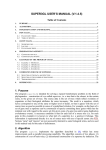
run body {
o2 Relative nsam = new Relative, nlana = new Relative,
nsue = new Relative;
o2 Parentage sl = new Parentage, ss = new Parentage;
/* Define the three nodes */
nsam->content = Sam;
nlana->content = Lana;
nsue->content = Sue;
nsue->position = tuple (x: 20, y: 30);
nlana->position = tuple (x: 50, y: 10);
nsam->position = tuple (x: 10, y: 10);
/* Define the two links */
sl->drawing = list();
sl->from = nsue;
sl->to = nlana;
ss->drawing = list();
ss->from = nsue;
ss->to = nsam;
/* Define the graph value */
Tree = new Genealogy;
Tree->origin = tuple (x: 0, y: 0);
Tree->real_size = tuple (width: 60, height: 40);
Tree->screen_size = tuple (width: 200, height: 200);
Tree->nodes = set (nsue, nlana, nsam);
Tree->links = set (sl, ss);
}
Once the object Tree is initialized, the following code
will display it.
run body {
Lk_presentation p;
Lk_mask ma = lk_generic();
p = lk_present (Tree, lk_object(0, 0, 0,
lk_specific("genetree", 0, 0, "graph", 1, &ma)));
lk_map (p, LK_MANUAL, 0, 0, 0, 0);
lk_wait(p);
lk_delete_presentation(p);
}
54
O2 Graph User Manual
Programming example using GraphDialoger :
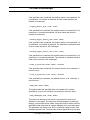
Executing this program results in the presentation shown in Figure [Ref:
plgnone] . Note that the nodes are deliberately out of balance; there is no
layout manager in action here. Executing the same program with the
resource doLayout set to true and the resource layout specified as
"tree" results in the presentation that we saw in Figure [Ref: plgtree].
Figure 3.4: A graph display without a layout manager.
Imagine, however, that we wish to use the GraphDialoger, and so allow
the user to add links and nodes to fill out Sue’s ancestor chart. We must
require that the links of the graph must make genealogical sense.
For example, since no person can have more than two parents, we shall
forbid the addition of a link from one object of class Relative to another
if that object is already the destination of two links. Furthermore, since
an ancestor chart does not deal with siblings, we shall also forbid the
representation of more than one child for a parent (that is, more than one
link of which the parent is the origin). This requires that we create a callback method for the class Genealogy. Let us call it check_parents.
O2 Graph User Manual
55
6
O2Kit Toolbox Features for the
method public check_parents (g: Graph, l: Link) in class Genealogy;
method body check_parents (g: Graph, l: Link) in class Genealogy
{
o2 Node parent = l->get_origin, child = l->get_destination;
o2 set(Link) links;
o2 Link lnk;
int ok = 1, ct;
/* Check how many children the parent already has (max allowed = 1) */
links = self->get_links (parent);
ct = 0;
for (lnk in links where (lnk->get_origin == parent))
ct++;
if (ct > 0)
ok = 0;
/* Check how many parents the child already has (max allowed = 2) */
links = self->get_links (child);
ct = 0;
for (lnk in links where (lnk->get_destination == child))
ct++;
if (ct > 1)
ok = 0;
/* If violation, remove the new link */
if (!ok) {
(self->dialoguer)->remove_link (l);
}
The GraphDialoger display is initialized and constructed with the
following code :
56
O2 Graph User Manual
Programming example using GraphDialoger :
Lk_presentation p;
Lk_resource res_graph[1];
Lk_mask node_mask = lk_generic(), graph_mask, obj_mask;
o2 GraphDialoger gd = new GraphDialoger;
char objectstring[16];
/* Link graph object and GraphDialoger object */
strcpy (objectstring, gd->initialize);
Tree->dialoguer = gd;
/* Put result of initialize method in the "dialoger" resource */
res_graph[0].name = "dialoger";
res_graph[0].value = (char*) malloc (strlen (objectstring)+1);
strcpy (res_graph[0].value, objectstring);
/* Set call-back for link insertion (event 4) */
gd->set_trigger_event(4, Tree, "check_parents");
/* Display the graph */
graph_mask = lk_specific ("genetree", 1, res_graph, "graph", 1, &node_mask);
obj_mask = lk_object ("geneobj", 0, 0, graph_mask);
p = lk_present (Tree, obj_mask);
lk_map (p, LK_MANUAL, 0, 0, 0, 0);
lk_wait(p);
lk_delete_presentation(p);
}
O2 Graph User Manual
57
6
58
O2Kit Toolbox Features for the
O2 Graph User Manual
IN DEX
O2Graph User Manual
INDEX
A
add_link 41, 50
add_link_between 41 , 50
add_node 41 , 49
add_unmanaged_node 49
Addin g a lin k 37
animate 33
Ar ch itect u r e
O2 8
arrowHeight 20
arrowStyle 20
arrowWidth 20
attachFrom 20
attachTo 21
autoLinkSelect 21
B
Back gr ou n d display 10
background of gr aph 15
Bitmap class 10
C
C 9
C++
In t er face 9
60
Class
Bitmap 10
Drawable 10
Gr aph 40
Image 10
Link 14
Node 14
clear_all 48
consult_node 50
content of n ode 16
D
Data str u ct u r es 14
delete_link 41
Display 18
Back gr ou n d 10
doLayout 21
Drawable class 10
drawing of lin k 16
E
Edit or
Gr aph 10
graph 14 , 18
Specific 18
epsilon 33
extend_select_link 48
extend_select_node 48
extend_toggle_select_link 49
extend_toggle_select_node 49
O2Graph User Manual
INDEX
F
I
from of lin k 16
Image class 10
import schema 10
initialize 44
isi layou t m an ager 30
G
get_destination 43
get_links 42
get_nodes 42
get_origin 43
get_position 42
gr aph
Edit or 14, 18
Resou r ces 18, 19
Graph class 40
Gr aph editor 10
H
hGap 29 , 31
hGrid 26
hMargin 21
hOrigin 26
horizontal 27 , 29
hSize 22
hSizeMax 22
J
J ava 9
L
label of lin k 16
layout 22
Layou t Man ager s 11
isi 30
spr in g 32
tree 27
length 33
Link class 14
link_is_selected 49
linkClass 29
linkColor 22
linkNewProcess 22 , 47 , 48
links of gr aph 16
linkThickness 22
lk_specific fu n ct ion 18
loadfile m et h od 10
O2Graph User Manual
61
INDEX
M
manage_node 50
M ask s 18
maxHeightVisible 22
maxInRow 27
maxIter 33
maxWidthVisible 22
M et h od
Graph Class 40
GraphDialoguer class 44
loadfile 10
Node class 42
o2kit 39
minHeight 23
minWidth 23
moveProcess 23
M ovin g a n ode 36
multiLinkProcess 23
O 2 Look 9
O 2 OD BC 9
O 2 Stor e 8
O 2 Tools 9
O 2 Web 9
OQL 9
origin.x of gr aph 14
origin.y of gr aph 15
P
position.x 15
position.y of n ode 15
Pr esen t at ion 18
N
Node class 14
node of gr aph 15
node_is_selected 49
nodeCutProcess 23 , 46
nodeNewProcess 23 , 47
O
O2
Ar ch it ectu r e 8
62
O 2C 9
O 2 Cor ba 9
O 2 DBAccess 9
O 2 En gin e 8
O 2 Gr aph 9
O 2 Kit 9
o2k it
Sch em a 10
R
real_size.height of gr aph 15
real_size.width of gr aph 15
refresh_node 50
remove_link 41 , 50
remove_node 41 , 50
Rem ovin g a lin k 37
Rem ovin g a n ode 36, 46
replaceProcess 23
resizeProcess 23
O2Graph User Manual
INDEX
Resou r ces 19
Gen er al 18
grid 26
isi 31
spring 33
tree 29
reversed 29 , 31
T
to of lin k 16
toggle_select_link 49
toggle_select_node 48
tree layou t m an ager 27
S
screen_size.height of gr aph 15
screen_size.width of gr aph 15
selBorder 23 , 45
selColor 24 , 45
select_all 48
select_link 48
select_node 48
Select ion of n odes an d lin k s 36, 45
selectProcess 24 , 45 , 46
selThickness 24 , 45
set_background 40
set_destination 43
set_origin 40 , 43
set_position 42
set_real_size 40
set_screen_size 40
set_trigger_event 44
show_node 50
showLabel 24
Specific edit or 18
spring layou t m an ager 32
Syst em
Ar ch it ectu r e 8
63
V
vGap 31
vGrid 27
vMargin 24
vOrigin 27
vSize 24
vSizeMax 24
O2Graph User Manual