1
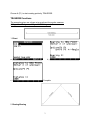
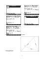
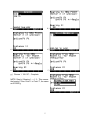
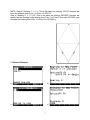
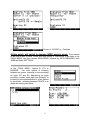
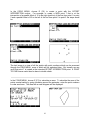
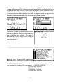
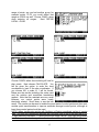
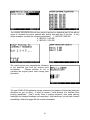
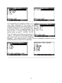
COGO-50 v1.81 User Manual
By Jacob Wall
COGO-50 is a (mostly) UserRPL program written for the HP 49g+/50g using ROM
Version 2.09 (also tested with ROM Version 2.15). It is a land surveying program
capable of performing common survey calculations. The software is provided free of
charge, as is, without any kind of warranty. This manual will provide some step by step
examples and briefly explain all the functions included in the library.
The first step is to attach Library 925 to Port 2 on your calculator. (For instructions on
how to do this please see the last page of this manual.)
Run the COGO-50 library by:
1. Entering the command COGO (in RPN mode) and then press ENTER
2. From the library menu (Right Shift, then 2)
3. From the APPS menu, at or near the bottom of the list
When running the program for the first time you will be prompted to choose a few
settings that will apply to all jobs you will create.
Choose your preference for angle measure, the
number of decimals displayed with output, pick
slope or horizontal distance for 3D-Traverse,
and choose between azimuth or quadrant
bearings. (Quadrant Bearings are entered as
QDD.mmss, N32°12’02”W would be entered as
432.1202)
A default job called “Default” is automatically
created if no jobs exist. All jobs created become subdirectories in the JOBSCOGO
directory in HOME with a *.c50 extension to ensure unique names. Job names can be
alpha, alphanumeric or numeric.
1
MAIN MENU
The MAIN MENU is where you access all other sub-menus. Note: The current job
name will always appear on the first line of the MAIN MENU.
A COGO MENU
The COGO MENU features all the basic COGO functions. Choose C (F3) to ENTER a
point number & ASSIGN coordinates to it. Enter values in each field and hit OK. All
fields will clear and the form will be ready for another point to be entered. You can keep
entering points until you choose CANCL, which will return you to the COGO MENU.
2
Choose A (F1) to start creating points by TRAVERSE.
TRAVERSE functions
The examples given are shown using grads as the angular measure.
(100 grads = 90 degrees, 400 grads = 360 degrees)
1. Direct
a.)
c.)
b.)
Complete
2. Bearing-Bearing
3
a.)
b.)
c.)
d.)
e.)
Complete
3. Bearing-Distance
4
a.)
b.)
c.)
d.)
e.)
f.)
g.) Choose 1. 108.127 – Complete
NOTE: Step b.) Bearing 1: = 1 3 - This means:
the bearing “From Point 1 to Point 3”, the same
as 50.0000 g
5
4. Distance-Bearing
a.)
b.)
c.)
d.)
e.)
f.)
Choose 2. 75.1596 g – Complete
6
NOTE: Step d.) Distance 1: = 1 4 - This is the same as entering 108.127 because we
know the distance from Point 1 to Point 4 is 108.127
Step e.) Bearing 2: = 1 2 100, This is the same as entering 200.0000, because we
specify that the bearing is the bearing from Point 1 to Point 2, then add 100.0000, and
we know the bearing from Point 1 to Point 2 is 100.0000 g
5. Distance-Distance
a.)
b.)
c.)
d.)
7
e.)
g.)
f.)
Choose 2. 166.6667 g – Complete
At this point I will switch to degrees (HMS) angular mode. Press cancel
at the next prompt to enter FROM and NEW points in TRAVERSE to get back to the
COGO MENU, and then choose MAIN MENU, followed by DATA MANAGER, then
JOBS and finally SETTINGS.
In the COGO MENU, choose B (F2) to
INVERSE.
You have options of inversing
between two points, inversing a curve providing
an origin, BC and EC, determining an angle
providing a vertex, back sight and foresight, or
inversing a point perpendicular to a line defined
by two points. Inversing between POINTS is as
simple as entering two points.
8
Inversing a CURVE requires an origin and two points equally distant from the origin.
From point 6 created earlier by distance-distance we can use point 1 as a BC and point
2 as the EC.
Inversing an ANGLE requires a vertex point, a back sight point and a foresight point.
Using the same points as in the CURVE example:
Inversing a POINT TO LINE requires a point of interest whose perpendicular distance,
or tie distance, to a line formed by two other points is of interest. For example the tie
distance of point 4 to the line formed by points 1 and 2. The tie distance, distance from
start of line and to end of line that this occurrence takes place, and line distance and
bearing is provided as output.
9
In the COGO MENU, choose D (F4) to create a point with the OFFSET
INTERSECTION routine. For example, to create a NEW point 7 that is at the
intersection of a parallel offset of 15 to the right (positive) of the line from point 1 to point
2 and a parallel offset of 20 to the left of the line from point 2 to point 5 the steps would
be:
The last image is a view of all the points with point numbers which can be accessed
through the VIEW MENU, more of which will be explained later. But visually we can
verify that point 7 is indeed at the intended OFFSET INTERSECTION point. A POINT
TO LINE inverse could also be done to double check.
In the COGO MENU, choose E (F5) to calculate an area. To calculate the area of the
points created earlier by going clockwise around the perimeter, enter the point numbers
in order as shown. The area with a small diagram will be displayed.
10
To calculate an area with circular features the order is BC, the Origin as a negative
number followed by the EC. Compound curves require the point of compound curve to
be entered twice, once for the EC of one curve, then again as the BC of the next curve.
NOTE: The portion of the curve less than 180° will be calculated, so if the area contains
a circular portion with a delta angle of over 180°, you’ll need to break up the curve into
two parts, creating a compound curve with equal radius. As an example:
You will be prompted to choose to either add or
subtract the segment described; in this case we
want to subtract the segment. The area is
calculated as if the BC and EC join in a straight
line and since the segment is inside the line or
area, we subtract it.
B ADJUSTMENTS MENU
The ADJUSTMENTS MENU features all the point adjusting and manipulating programs.
Let’s consider the following P,N,E coordinates: 10,10000.000,10000.000
11,11643.528,10000.047
12,11645.621,11640.584
13,9999.380,11640.907
14,10000.024,10000.080
11
Say those are the coordinates derived given distances and bearings. Point 14
represents where the data closes, and the difference between point 14 and point 10 is
the mis-close. After entering those coordinates using ENTER & ASSIGN, choose A
(F1) in the ADJUSTMENTS MENU to perform a COMPASS RULE ADJUSTMENT.
Enter the points in order as shown:
The first screen to follow point entry will show
the precision of the adjustment with an option to
apply the compass rule by overwriting the
existing
coordinates
with
the
adjusted
coordinates. Point 5 and point 1 will then have
the same coordinates. If you choose “Yes” you
will see further explanations of the adjustment, if
you choose “No” then your original coordinates
will remain unchanged.
In the ADJUSTMENTS MENU chose B (F2) to rotate points around a base point by a
specified rotation angle. For example rotating points 11, 12, 13, and 14 around point 10
clockwise by 90° would be done like this: Positive angles indicate clockwise rotation. A
message box verifying successful rotation follows unless invalid data was entered.
Points are entered as a range FROM TO.
12
In the ADJUSTMENTS MENU choose C (F3) to move points. You have the option to
move a range of points by a specified delta Northing and delta Easting or by 2 reference
points. Choosing option: 1. BY ∆N, ∆E simply allows you to do just that.
After entering the delta Northing and Easting you
can enter the range of points that you wish to
move. A message box verifying successful
points moved will be displayed upon completion.
To move points by reference points chose 2. BY
REFERENCE POINTS, and simply enter the two
reference points you wish to use. Moving points
10 to 14 so that 10 moves to where 11 now is,
do the following:
The result will be all points being moved the difference in Northings and Eastings
between the original point 10 and 11.
13
In the ADJUSTMENTS MENU choose D (F4) to
scale points. You can either scale the points
from a base point (0,0) or from any existing
point.
After choosing either you will be
prompted to enter a scale factor and the range
of points you wish to scale. Same look and feel
as the move and rotate commands.
In the ADJUSTMENTS MENU choose E (F5) to transform points. The TRANSFORM
POINTS routine lets you have two separate groups of points in the same job on different
coordinate systems and orientation and pick control points from both groups, then move
one group for a least squares fit into the other coordinate system. The two groups are
called LOCAL and PLAN. LOCAL points are points that will be moved, PLAN points will
not move. I will use a very simple example to illustrate how this routine works. For
PLAN points I will use only three:
20,2000,2000
21,2100,2100
22,2000,2200
or a triangle
For LOCAL points I will use five points, three of which will relate to the PLAN points, the
other two just randomly placed. 30,3022.636,2971.543
31,3071.005,3104.436
32,2938.112,3152.804
33,2918.611,3180.656
34,3075.499,3036.823
Point 20 will relate to 30, 21 to 31 and 22 to 32. To check that they in fact have the
same relation and only are rotated and moved, you can calculate areas or inverse
between points and inverse angles. Below are areas for 20 21 22 on the left and 30 31
32 on the right.
Having defined our points, we can now transform the 30-34 points group into the 20-22
coordinate system. In the ADJUSTMENTS MENU choose E (F5) to perform a point
transformation. You will see four options, defining a local range, defining local to plan,
calculate and cancel. You will need to define the local range and the local to plan points
before calculating. First DEFINE LOCAL RANGE. You can have more than one local
14
range of points, say you had another group, for
example points 15-19, you could define that
range as LOCAL as well. Choose CANCL when
done entering all ranges.
Next DEFINE
LOCAL→PLAN.
Choose CANCL when done entering all local to
plan points. Next choose CALCULATE. You
will be given the option to scale the local
coordinates to best fit the plan coordinates. If
you choose NO, a scale of 1 will be forced.
Below are the results including the scale used
and the rotation and coordinate translations
applied. Note that the residuals are very small
because our control points were nearly
identically related. Scroll down to see the last
result. The results can be used to isolate the worst pairs of control points and then redo
another point transformation to improve residuals amongst control points, although at
least three control pairs should be used.
NOTE: When transforming points with Northing or Easting coordinate values of greater
than ~100,000 you’ll notice the residuals are not good, this is due to the fact that it is a
12 digit precision calculator. To work around this simply “MOVE” your Plan points down
to a lower coordinate value, perform the transformation and then “MOVE” the Plan and
15
the transformed Local points back by the same values. You may need to move the
Local points prior to Transformation if their coordinate values are also high.
If you go to the VIEW MENU you can verify that
the coordinates of the control pairs are now
matching. The VIEW MENU will be covered
next.
C VIEW MENU
At this point I will delete some of the points created earlier to better illustrate the view
abilities. From the MAIN MENU choose JOB MENU, then DELETE POINTS and delete
a RANGE OF POINTS from 1 to 19.
The VIEW MENU is where you can view all points and coordinates. Choose POINTS
WITH NUMBERS to view all the points plotted to scale fitting the calculator screen. For
example to view all points from the transformation example, the results would be, WITH
POINT NUMBERS on the left, and WITHOUT POINT NUMBERS on the right:
16
Not the greatest representation once you have a job with many points as point numbers
will become increasingly difficult to read but still gives a decent visual.
ALL COORDINATES, as shown earlier this produces a screen showing all point
coordinates, press GRAPH for larger text.
Choose POINT COORDINATES to view coordinates for individual points.
17
D TOOLS MENU
The UTILITIES MENU features a variety of tools related to land surveying. Version 1.5
has a new triangle solver which allows you to enter the three knowns and the solver will
solve for the remaining parts. The fields in the input form are listed in order of angle,
side, angle, side, etc. going around a triangle. For example known Angle A as 45,
Angle B as 45 and Side a as 45, (AAS) the solver will solve the remaining unknown
parts and the area.
The CIRCULAR CURVE SOLVER requires either the radius or deflection angle (or
both) and any other of the horizontal circular curve parameters. For a curve of radius
500 and a delta of 45 you get the unknown parts as well as sector, segment and fillet
areas.
The VERTICAL CURVE SOLVER asks for the entry and exit gradients, the length of
curve and the station and elevation at the BVC, EVC, VPI, or the HIGH/LOW point of
the vertical curve. For example: A 500 m long curve with an entry gradient of +6.00%
18
and an exit gradient of -2.00% with a VPI station of 44+00 and VPI elevation of 275.750
m.
You will initially see the solutions of the curve
defining stations, but after pressing OK, you will
see two further options: Solve for an elevation at
a specified station, or solve for elevations at a
specified station interval. First to solve for the
elevation at station 45+67.890, then secondly to
solve for each 20 m station, as shown in the
following screens.
19
The LINEAR REGRESSION tool fits a series of points to a statistical best fit line with an
option to overwrite the points entered after seeing how well they fit the line. A very
simple example, consider the following coordinates: 1, 1000.000, 1000.000
2, 1000.010, 1149.987
3, 1000.032, 1235.000
The results shown are perpendicular distances
to the statistical line from the original point
coordinates.
Choose whether or not to
overwrite the original points once having seen
the results.
The new LEVEL-RUN application simply calculates your heights of instrument and point
elevations as you go along. If there is interest I could develop it to facilitate other
leveling capabilities. How it works: Enter a starting elevation, then keep entering
backsight and foresight readings until completed. After each input you will see a screen
resembling a field book page with the current information.
20
And so forth. Press ENTER on an empty
backsight field to enter intermediate foresights,
the last one input will be used to continue, press
CANCL at a backsight prompt to finish the Level
Run. You can view the last Level-Run report
from the VIEW MENU, choosing View Level-Run
Report.
The 3D-Traverse application allows traversing
inputting horizontal and vertical angles, as from
a Total Station. To start enter a setup, or
Occupy, point, the height of instrument and a
correction angle if desired.
Next you are
prompted to enter horizontal and vertical angles,
a distance, and depending on your settings,
either slope distance or horizontal distance and
a height of target. Finally you are asked to
provide a point number for the coordinates that
are created. You can keep doing “sideshots” until you CANCL out.
21
The Inaccessible point application allows you to
enter setup information of two points and
corresponding horizontal and vertical angles to
calculate coordinates for the inaccessible point,
ie, the peak of a roof. A simple example: First
setup on point 1, N=1000, E=1000, Z=10, and
second setup on point 2, N=1000, E=1100,
Z=10, the height of instrument at both setups is
1.600 m. The solution is automatically given a
point number and you will see the coordinates
displayed. The average elevation is used, if there is discrepancy between the two
possible elevations, a input error is quite likely.
22
E DATA MANAGER
The DATA MANAGER offers data related
routines. JOBS is a sub menu where you can
create, load or delete a job and change job
settings. CREATE was seen at the start of the
program. LOAD and DELETE both present a list
of all the jobs created and you are able to
choose which job to either load or delete.
SETTINGS allows you to change angular
measure and linear precision. ABOUT COGO50 displays my name and email address.
23
In the DATA MANAGER choose B (F2) to
IMPORT POINTS in the form of a delimited text
file. NOTE: At this time be aware that only P,N,E
and P,N,E,Z text files can be imported, space or
comma delimited, and also when importing points
all the points in the current job will be deleted, so
create a new job before importing.
Example: If you have a *.txt file on your computer
the easiest way to import those coordinates into
COGO-50 is to copy the *.txt file onto an SD card
and then into the HOME directory. Of course the
connectivity kit can also be used. Once the text
file is on the calculator put it in stack level one
and launch COGO-50.
Once chosen to
CONTINUE with IMPORTING you will need to
choose either the P N E, P N E Z, P E N or P E N
Z format and hit OK, after which the points will be
imported into the current job. The larger the text
file, the longer it will take to import.
In the DATA MANGER choose C (F3) to
EXPORT POINTS. This program creates a
string (text) of all the points in the current job.
You can choose to either save the file directly
onto the SD card or into the current job subdirectory in the JOBSCOGO directory. The files
will be created with a *.txt extension. After
transfering the text file to the computer you will
need to edit out the header that the HP
calculator puts in automatically. The easiest
way to do this is to open the *.txt file using WordPad and simply deleting the first line
and saving it, after which you can open it using Notepad or import it into a CAD
program. If you use Notepad first to edit out the header you will see that some of the
characters don’t translate and create a mess.
24
In the DATA MANAGER choose D (F4) to
DELETE POINTS. You have the option to
delete all points in the current job or to enter
individual points, separated by spaces, or
specify a range of points to delete. For example,
if you have a job with points 1 to 5 being the only
points in the job, the following will delete all five
points. First ALL POINTS is the easiest and
quickest.
In the DATA MANAGER choose E (F5) to RESET JOBSCOGO. This routine deletes all
data from the JOBSCOGO directory and leaves an empty directory. Can be useful to
clean out a bunch of old jobs created which are no longer needed.
As of April 2009, further development of this free software is unlikely since I have
completed a much more capable program called COGO·50·Plus. I will continue to
support this program, answer any questions, and fix any bugs if they should be found.
Contact me by email: [email protected]
New in Version 1.8
‐
‐
‐
‐
‐
‐
Removed dependency on the Development Library (Library 256)
Fixed a bug with bearing-distance intersections
Removed Intro Splash Screen (Version 1.81)
Fixed Overflow Bug that could result in a crash (Version 1.81)
Fixed potential crash in Inverse Point to Line (Version 1.81)
Updated manual to provide better installation instructions (Version 1.81)
25
New in Version 1.7
‐
‐
‐
Added Coordinate display setting to choose Northing Easting or Easting Northing
Removed menus from Area and View Points screens
Eliminated more potential crashes when pressing ON (Cancel) from various
routines
New in Version 1.6
‐ Added option to choose Quadrant Bearings or Azimuths as "Bearing" input/output
‐
‐
for direction
Fixed an issue that arises when importing points that are not listed in numerical
order in the ASCII file
Version 1.61 fixes compatability bug when upgrading COGO-50 from Versions
1.0, 1.1 or 1.2
New in Version 1.5
‐
‐
‐
Program accepts job names to be alphanumeric, numeric or alphabetic
Fixed bug in “Inaccessible Point” program
New triangle solver
New in Version 1.4 – (not necessarily a complete list)
‐
‐
‐
‐
Cleaned up a lot of the code to improve speed and reduce program size.
Fixed a few bugs.
More changes regarding menu appearances.
TRAVERSE and ENTER & ASSIGN now “remember” the next point number after
the highest point number in the job so you don’t have to.
New in Version 1.3 – (not necessarily a complete list)
‐
‐
‐
‐
‐
Settings now apply to all jobs, no longer necessary to select settings for each job
you create.
Some changes with menu appearances.
In TRAVERSE if the FROM point does not exist you are prompted to enter
coordinates for the point, now you will not be asked to input the FROM and NEW
point again after entering the coordinates.
VIEW all points, with or without point numbers, now simply acts as “View
Extents” rather than fit width of screen which then could require scrolling up or
down to view all points.
Coordinates are created as 3D, with some supported uses for elevations.
26
‐
A new and improved set of TOOLS including a vertical curve solver, a linear
regression utility, a level-run application, a 3D-Traverse application and a
inaccessible point utility.
Installing COGO-50 Version 1.81
First of all, if you happen to have an old Flat-Earth Surveys library or a previous version
of COGO-50 on your calculator, please PURGE it.
Purging existing copy of COGO-50
Step 1: Open the File Manager on the calculator (Left Shift, then APPS key)
Step 2: Press the 2 key to browse Port 2 (Assuming COGO-50 is installed there)
Step 3: Locate COGO-50 and highlight it
Step 4: Press the NXT key (L)
Step 5: Press the F1 (A) key (softkey labeled PURGE)
Installation using SD card.
Step 1: Copy file COGO181.LIB to SD card using your computer
Step 2: Insert card into calculator.
Step 3: Open the File Manager on the calculator (Left Shift, then APPS key)
Step 4: Press the 3 key to browse the SD card.
Step 5: Locate COGO181.LIB and highlight it
Step 6: Press the COPY softkey (B)
Step 7: Up arrow to 2: FLASH, then press the OK softkey (F)
Step 8: Hold down the ON key, then press the F3 (C) key, then release both
Installation using Conn4x:
Step 1: Open directory containing file COGO181.LIB
Step 2: Right click on the file and select “Copy”
Step 3: Open Conn4x on the computer
Step 4: Attach USB cable, type command XSERV on the calculator, press ENER
Step 5: In Conn4x, from the File menu select “Connect”
Step 6: Click on OK in the dialog box that pops up
Step 7: From the Edit menu, select “Paste”
Step 8: From the File menu, select “Disconnect from the calculator”
Step 9: On the calculator make sure you’re in HOME directory, press VAR key
Step 10: Press the F1 (A) key to return “Library 925: COGO-50 v1.81” to the stack
Step 11: Type 2, then press the STO key
Step 12: Hold down the ON key, then press the F3 (C) key, then release both
Step 13: Purge the variable ‘COGO181.LIB’ from the HOME directory
27