1
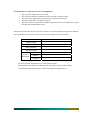
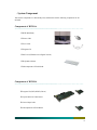
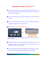
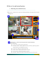
User’s manual Digital Video Recorder VideoWave Networks Inc. 7493 Trans-Canada highway #103, St-Laurent (Quebec) H4T 1T3 Tel.: 514-668-1845 Fax: 514-789-0878 www.videowave.ca [email protected] Before you begin… ========================================== = = = = = = = = = = = = = = = = = = This documentation explains the configuration of the DVR system (‘system’) and its program, and how to use them. Please read this user guide before you use the system. Check each component when you unpack the package, and contact the supplier if you have any question. Safety Notice (Please Note) ========================================== = = = = = = = = = = = = = 1. Notes before installing the product Take out the components and place them on a dry and flat floor. The rear part of the system must be 15cm from the wall. Install in a well ventilated place. It is inappropriate to install the system in a place where electromagnetic waves and strong magnetism are generated (e.g. near speaker, etc.) It is inappropriate to install the system under a direct ray of light or near the thermal equipment such as a heater in order to protect the system. It is inappropriate to install the system in a cold place exposed to outside. Be careful not to damage the system by other tools or equipments in the work area.. It is inappropriate to install the system in a severely shaking or humid place. Please check the voltage you use before connecting the power cord. (This system is produced to be used with 220V. To use the system in an area where 110V is supplied, adjust the conversion switch of the power section in rear of the system.) Connect the power cord. After you have taken out the components, dispose the plastic wrapper (Keep it out of reach of children. It is very dangerous for a child to wear it on his/her head.) 2 2. Notes on using the product Please contact the supplier if the product does not function. If you personally dismantle the product to fix it, you may not receive the maintenance service. Please make sure to read the user guide before using the product. When dismantling or repairing the product inevitably, please carefully handle it since the components are very sensitive. For your safety, do not touch the power cord or outlet with wet hands. Please be careful to correctly plug in the power cord to an outlet. Do not Do not touch the exposed terminal, if possible. Before you shutting off the system power, end all programs and its related auxiliary programs. clean the product with a substance containing alcohol like thinner and benzene. (If the system does not shut off, use the Power button in front of the system. Operate the system near the magnetic body or in a well ventilated area. Do not dismantle or repair the system at discretion. Do not place any heavy item on the system. Do not move the system while operating the system. If smoke coils from the main body or it smells strangely, immediately turn off the power and contact the supplier for the technical assistance and maintenance. Guarantee ========================================== = = = = = = = = = = = = = = = = = If the system does not function properly, we replace the components or system. The guarantee period can be extended by a separate agreement. Please ask your supplier for more information. Conditions of maintenance ========================================== = = = = = = = = = = = = = = = = = If the system malfunctions within 1 year from the purchase date, we replace the components or system free of charge (Please understand that free replacement service is not available if the system fails due to user’s careless operation or a natural disaster.) 3 Free maintenance or replacement service is not applicable if: 1. 2. 3. 4. 5. The system was stopped due to a user’ fault. The user did not follow the instructions in the user guide in using the system. The rated voltage and frequency specified in the user guide were not used. Replacing consumables or cleaning the system. The system failure occurred after an unauthorized person who did not complete the required training course dismantled the system. After the free maintenance period is expired, you can have your system upgraded or repaired at minimum expense. Should you require these services, please ask your supplier for more information. Product Name Product Number Supplier / Telephone Date of Purchase Guarantee Period Customer Information Name Address Telephone We do not issue the information above on the product purchase. Please understand the details and conditions from the supplier when you make purchase. You should show the information above when requesting a maintenance service. 4 INDEX . System Component . Introduction 1. System Features 2. Major Functions III. How to Use and System Functions 1. Monitoring Screen (Default Screen) 2. Environment Setup (System Setup) 2-1. System Setup 2-2. Resolution & Audio Setup 2-3. Camera Setup 2-4. Recording Schedule Setup 2-5. Network I 2-6. Network II 2-7. Sensor & Relay 2-8. User Setup 2-9. System Information 3. Search Function 4. Backup 4-1. Manual Backup 4-2. Schedule Backup 4-3. Manual Backup Viewer 4-4. Automatic Backup Viewer 5. Image Analysis 6. Log Viewer 7. Hardware and Connection Configuration 5 . System Component Take out the components in a flat and dry area, and then check if the following components are all included. Components of DVR Set ========================================== = = = = = = = = = = = = = = = = = = ⊠ DVR Main Body ⊠ Power Cable ⊠ User Guide ⊠ Program CD ⊠ OS Laved (Windows 98 or Higher Version) ⊠ Keyboard & Mouse ⊠ Subcomponents of Each Model Components of DVR Kit ========================================== = = = = = = = = = = = = = = = = = = ⊠ Program CD (DVR, RDVR, Driver) ⊠ Capture Board or Video Board ⊠ Camera Input Cable ⊠ Subcomponents of Each Model 6 7 . Introduction What is the DVR? ========================================== = = = = = = = = = = = = = = = = = = This system digitalizes and stores the analog video and voices on a storage device, and allows users to search by any criteria they specify and to transmit the image through a network. This is commonly known as the DVR(Digital Video Recorder). 1. System Features ========================================== = = = = = = = = = = = = = = = = = = 1) Stabilized System This system has been stabilized and verified by six years of research and development. 2) Efficient File System The system stores data on baskets which are the disk space partitioned into certain areas. This file system efficiently aligns data and maximizes the speed of data processing. In addition, the stored data is effectively protected. 3) Outstanding Image Quality and Search Methods The system provides various search conditions and an excellent image quality for searching an event or constantly saved data. 4) Convenient User Interface The system allows users to operate it with simple mouse operation in a GUI environment for convenience. 5) Various Network Functions The system provides the remote monitoring, recording, searching, sending, and controlling functions as well as the two-way voice communication through a network in real time. The transmission can also be enabled using a telephone modem and diverse networks. 2. Major Functions ========================================== = = = = = = = = = = = = = = = = = = Maximum 16 real time images can be monitored. 30 ~ 480 frames can be recorded, and the system is equipped with an efficient MPEG4 coder/decoder. Each camera can be operated with different compressing methods and recording speeds. The system uses the same method used to save file systems and provides a stable recovery function for file systems. The system provides the remote monitoring (LAN, PSTN, ISDN), Single & Multi RDVR, twoway voice communication functions. The saved data can be backed up using searching and various backup devices (DAT, DVD, ADR, DLT, CD-RW, On-Stream). Various searching methods: Event search, motion search, panorama search, search by minute, jog shuttle search, and search by camera combination System monitoring function (Watch Dog) Remote notification function ( PDA, email, text transmission ) Audio recording function The system distinguishes the function for each user and provides him/her appropriate account and password ( Multi-Level Password ) Various type of alarms (beep sound, moving line, enlarged screen, and email) 8 Remember Before You Start !!! ⊠ G.U.I (Graphic User Interface) : An operating environment designed to allow users to use a function by clicking or double-clicking it with a mouse on a screen. This system operates in a GUI environment. ⊠ If you move the mouse pointer to an icon, the description on its function automatically activates. ⊠ In order to use all functions upon starting the system, first release the key lock (user authorization) and enter the account and password. ⊠ Default setup value < account : admin / password : 1111 > Virtual Keyboard (For the system security, it is recommended to change the account and password after the user authorization.) ⊠ The watch-dog function which operates automatically at system failure has not been configured to operate at system startup. Check the watch-dog column in the environment setup when you start the system. ⊠ If you operate the system without camera input images at initial startup, the beep may sound. It is an alarm due to disconnection of images, and not a system failure. ⊠ For the system security, lock the key after using the system. 9 ⊠ If you connect the power after an abnormal termination, an “analyzing the file system” message window appears for system stabilization. ⊠ User guide common to all the models including the capture, live, 4ch, 9ch, and 16ch (unsupported menus are not activated). 10 III. How to Use and System Functions 1. Monitoring Screen (Default Screen) ========================================== = = = = = = = = = = = = = ⊠ When power is connected to the system, the following monitoring screen appears after the system booting process. 1 1 [M] OFFICE 1 [P][A] 2 [M] PARKING LOT [P] 4 5 4 [C] ATM [A] 3 [C] OFFICE 2 2 3 END 1 Monitoring Screen : Shows the camera image and camera connection information. [Camera Information] Camera Number : Displays the camera input number Recording Condition : Displays [N]Do not record, [C]Constantly, [M]Moving, [S]Sensor, [C&E]Constantly & Event [S&M]Sensor & Moving Camera Name : Displays the configured camera name PanTilt Connection : Displays [P] if the PanTilt is connected Audio Connection : Displays [A] if the audio is connected Red Outline : Displays the red outline around the image if there is an event in a camera 11 2 Screen Split : Use to configure the screen. [ Screen Split ] : Does not split the screen (manually or automatically converses the screen to a full screen) : Splits the screen into 4 sections (manually or automatically splits the screen into 4 sections or restores it.) : Splits the screen into 6 sections (manually or automatically splits the screen into 6 sections or restores it.) : Splits the screen into 9 sections (manually or automatically splits the screen into 9 sections or restores it.) : Splits the screen into 10 sections (manually or automatically splits the screen into 10 sections or restores it.) : Splits the screen into 16 sections. [ Screen Conversion ] : Manually reverses the screen : Manually forwards the screen : Automatically converses the screens (specify the time for conversion in the setup – maximum 10 seconds) : Fully enlarges the screen (double click the left mouse button in the monitoring screen to “enlarge”, or click the right mouse button to “reset” ) 3 Status Display Window : Connection of cameras and audios, channel selection, sensor input verification, relay control, image quality adjustment [ Camera Status ] Blue : Normal, Red : Disconnection of cameras, # Grey : Camera not used [ Audio Connection Status ] < Click a corresponding channel => listen to the current audio > Light Green : Selected channel (currently played audio) 12 Light Grey : Currently used audio channels, # Grey : Audio not used [ Sensor Input Verification ] Purple : Sensor input is enabled Grey : Signal is ready or not used [ Relay Control ] < Click a corresponding channel => display the relay > Yellow : Relay is operating Grey : Relay is ready or not used [ Image Quality Adjustment ] < Click a camera before adjusting the image quality > < lower left corner > Adjusted value automatically activates Brightness 2 Apply the adjustment value to all or apply the default value 4 Hue adjustment Saturation adjustment Contrast adjustment Brightness adjustment Index Information Window : Shows the current date, time, hard disk saving status, and network access information. Network Access Information : Shows the ID and IP of a user access from a remote site. “Double Click the Icon” ( Note : The system allows maximum 5 direct accesses to DVR through network at a time) Oldest Record Date 13 5 Function Buttons : Key Lock, Environment Setup, Search, Rotational Camera, Fast Search, Backup (Refer to each section for more information) Key Lock : Used for security purpose. (Requires an user authorization to release) < Default Account > admin < Default Password > Virtual Keyboard 1111 (It is recommended to change the account and password after user authorization for the security purpose) Environment Setup : Configures the system Search : Searches recorded image or audio PanTilt control : Click the PanTilt button to activate the control window as shown below (the control window can be moved with the mouse) Turns on/off the camera power Turns on/off the light power Turns on/off the AUX power Rotates to the direction specified Turns on/off the auto pan Specifies a camera (moves to the left or right) Zoom in (left), zoom out (right) Focus near (left), focus far (right) Configures the preset and moves Configures the touring and moves 9 Position the pointer to a button to activate a description window. 9 Some functions may not be supported depending on the type of receiver or speed dome camera used. [ How to Setup the Preset ] Click the button to activate the left window Move to the location of camera to specify Enter the preset number and description, and press the add button Add preset numbers using the same method (maximum 64) To execute the preset : Press the move button after specifying the number To edit the preset : Specify the relevant number, move to the camera and click the edit button. 14 To delete the preset : Specify the relevant number and click the delete button Click the save button before closing. Click the button to activate the window shown in the left. Enter the touring list using the preset number Enter the touring number and its description, and configure DW [ How to Setup the Touring ] (delay time) Complete by clicking the add button Enter the touring list using the same method (maximum 12) To execute the touring : Specify a number and click the move button To edit the touring : Specify the number, reenter the touring list, and click the edit button To delete the touring : Specify the number and click the delete button END Save the operation before closing. Fast Search : Searches an image and checks the content of an event with event signals Back Up : Executes a manual backup The button to end the program Click the “Exit” button. A window appears to confirm. Click “Yes” or “No.” 15 2. Environment Setup ( System Setup ) ========================================== = = = = = = = = = = = = = ⊠ The environment setup is used to configure the system operation including functions to use and the time to operate the system to meet the requirements of users. ⊠ Please note the following information. √ The setup menu consists of 9 tabs. When you finish operation for each tab, click the “Apply” button before moving to the next tab. √ If the system detects a failure, the watch-dog function reboots the system in specified period of time with the beep. The system is not configured with this function in the warehouse. Check the watch-dog setup column to use this function. √ If the beep is configured by interworking with event signals which is different from the watchdog function, the beep may be generated. For your reference, the system generates the beep when the camera signal is disconnected. √ Some functions automatically reboots the system when selected. These are available only after the system rebooted. √ Only four cameras are configured to constantly record the images in the warehouse. Setup the schedule, and the condition to record and use cameras as required by the field. √ Click the “Apply” button after configuring each tab and click “OK” to complete the setup process. Then, following window appears in the monitoring screen and the screen starts to blink within approximately 5 seconds while initializing the hardware and software. 16 2-1. System Setup ========================================== = = = = = = = = = = = = = ⊠ Click the “System” tab to open the setup window as below. 1 2 3 1 System Setup : Configures general system specifications. Camera Type : Select the NTSC or PAL Watchdog Setup : Select to enable this function and select the delay time (more than 100 seconds is recommended) Default Screen Setup : Select the default split screen after booting or environment setup Backup Setup : Click the “Setup” tab to activate the window for schedule backup setup. (Explained in more detail in the relevant section) 2 Full screen : Select to apply the full screen by default after booting or environment setup Disable Ctrl+Alt+Del : Select to prevent forced termination and booting. Enable Event Search : Select to enable the event search in the monitoring screen TV Out Conversion Mode : Configures external monitor (TV) display Manual Conversion : Displays only the camera images specified in the monitoring window to a TV (applies in the same way when specifying the PanTilt numbers) Automatic Conversion : Only selected camera images are automatically conversed after specified time. (The cameras must be specified after selecting the automatic conversion to display the images to a TV) 17 3 Manual and automatic conversion TV out are supported for the capture model only. Automatic System Restart / Automatic System Termination : Specifies the schedule. Click the “Setup” tab to activate the following menu window. Specify ‘daily’ or a day of the week and the time. Automatic System Restart : Automatically reboot the system at the selected (specified) time. (Automatic restart does not run when the system is terminated, but runs while the system is operating) Automatic System Termination : Terminates the system at the selected (specified) time. 2-2. Resolution & Audio Setup ========================================== = = = = = = = = = = = = = ⊠ Click the “Resolution” tab to display the following setup window. 1 2 3 4 18 1 Camera Selection: Select a camera to configure. Camera Selection : Select a camera to apply the configuration (to select the setup values for a specified camera) 2 Environment Setup : Configure the resolution environment Resolution : Select one of saved resolution ( NTSC : Select one from 640 x 480, 640 x 240, or 320 x 240) ( PAL : Select one from 720 x 588, 720 x 288, or 360 x 288) Record Speed Setup : Select the record speed of the selected camera (Select from 1~30 fps; Those exceeding the maximum capacity is recorded within the saving capacity of the system.) 3 MPEG4 coder/decoder image quality : Select one out of three image qualities “Apply All” tab : Use to apply the same condition to all cameras Voice Selection : Configures the audio Audio to Use : Select the input number of audio to use (The audio number needs not to be same to the camera number.) 4 Audio Live : Select the audio to hear now Audio Record : Select the audio to record now Audio Control : Adjust the input audio level (check with the “practice” tab) Refer to this window to check the application of configuration of all cameras selected in the “Resolution” tab. Menu can be extended horizontally when checking the details. 19 2-3. Camera Setup ========================================== = = = = = = = = = = = = = ⊠ Click the “Camera” tab to display the following setup window. 1 2 3 4 5 1 Camera Selection : Select a camera to configure. Camera Selection : Select a camera to apply the configuration (to select the setup values for a specified camera) 2 Camera Description : Enter the camera description (name). 3 “Apply All” tab : Use to apply the same condition to all cameras Camera Description : Enter the name of the camera (image) (example, exit door). Image Quality Adjustment : Adjust the camera image quality (color) for optimization. Brightness : Adjust the brightness of the camera image Contrast : Adjust the contrast of the camera image Saturation : Adjust the saturation of the camera image Color : Adjust the color of camera image Default : Click to restore the default configuration set in the warehouse. 20 4 Detection Area Setup : Select the sensitivity and the area to detect motion. [ How to Setup the Motion Area ] Entire Area : Checks the motion of entire camera image. Partial Area : Click the “Add” button after selecting the “Partial Area”, and then drag the mouse in the left screen to configure the area (maximum 10 partial areas can be added). How to Delete the Partial Area : Click the “Select” tab, click the partial area to delete, and then click the “Delete” button. Delete All : Click the “Delete All” button to delete all partial area added. [ How to Setup the Motion Detection ] => [ Sensitive 0 ---- 100 Insensible ] 5 Rate of Detection : the level of detecting unnecessary motion by noise, defaulted at 10. Sensitivity : the level of detecting little motion in small point, defaulted at 10. The motions are checked by both the rate of detection and the sensitivity for accuracy. Click the “Test” tab to display the status of testing motions on the screen. PanTilt Setup : Configure the PanTilt (rotational camera) to use. Click the “Setup” tab to activate the following setup window. Camera Selection : Select the camera the PanTilt is connected. Receiver Setup : Check the “Enable” to activate the setup menu. Select the port, type, communication speed, parity, data bit, and stop bit. The configurations supported for the receiver or speed dome camera are listed in the table 21 The configurations supported for the receiver or speed dome camera. index Receiver Baud rate parity Data Bit Stop Bit Preset 0 Dvna 9600 N 8 1 X 1 DY 9600 N 8 1 X 2 Fine 2400 N 8 1 X 3 Kalatel(N/A) 9600 N 8 1 X 4 Linlin 9600 N 8 1 X 5 Panasonic(wv-cs850) 19200 N 8 1 X 6 Pelco D 2400 N 8 1 O 7 Philips(tc8560,tc700) 9600 N 8 1 X 8 Serim 9600 N 8 1 X 9 Sungjin 4800 M 8 1 X 10 Vicon 4800 N 8 1 X 11 Dyuni 9600 E 8 1 X 12 MP200 9600 N 8 1 X 13 KD6 9600 N 8 1 X 14 Samsung(scc-641) 9600 N 8 1 X 15 Oriental 2400 O 8 1 X 16 Techwin 9600 N 8 1 X 17 OMNIVIEW 9600 N 8 1 X 18 CNB 9600 N 8 1 X 19 CTNCOM 9600 N 8 1 X 20 NIKO(NK-97CHE) 9600 N 8 1 X 21 SENSORMETIC 9600 N 8 1 O 22 NEOSSRX-1 4800 E 8 1 X 23 PT101 9600 N 8 1 X 24 PANASONIC V12 19200 N 8 1 O 25 VICONEXT N 8 1 X 26 SECURTEX_B 4800 N 8 1 X 27 SMAILCAM 19200 N 8 1 X 28 DRX502A,DSC-230S 9600 N 8 1 X 29 HSDN-251 9600 N 8 1 O 30 SAMSUNG SRX100A 9600 E 8 1 X 31 CNB-SMART 9600 N 8 1 X 32 HL(HRX-1000) 9600 N 8 1 X 22 index Receiver Baud rate parity Data Bit Stop Bit Preset 33 DVRX_1000 9600 N 8 1 X 34 FastraxII_HID2404 9600 N 8 1 O 35 SAE 9600 N 8 1 O 36 KTD_313 9600 N 8 1 O 37 VSD_640 9600 N 8 1 O 38 AD1650/2050 9600 N 8 1 X 39 KTS-2000 UltraDome 9600 N 8 1 O 40 DYSPD-255 9600 N 8 1 O 41 KRE-301/302 9600 N 8 1 X 42 Pelco-D ( Cynix ) 9600 N 8 1 O 2-4. Recording Schedule Setup ========================================== = = = = = = = = = = = = = ⊠ Click the “Recording Schedule” to display the following setup window. 1 2 3 4 5 6 1 Camera Selection : Select a camera to configure. Camera Selection : Select a camera to apply the configuration (to select the setup values for a specified camera) 23 2 “Apply All” tab : Use to apply the same condition to all cameras Camera Setup : Select to use a camera, secret mode, and date display. Use : Check to select the camera Use Secret Mode : Images do not appear on the monitoring screen, only recording function is used. (Apply this function to the areas that should not be exposed, for example, inside the safe. 3 Date Display : Check to save the time and date on the recorded image. Event Notification : Select the screen configuration and the beep to be generated when there is an event in the system.. (Specify the ‘Enable Event’ when you select this function, otherwise it is not saved.) Full Screen : The split screen fully enlarges when there is a system event. Beep : Generates the beep when there is a system event. Display : Displays the red outline around the image when there is a system event. 9 Note : The above function restores when double clicking the relevant camera in the corresponding monitoring screen. 4 Before and After Recording Setup : Configure the time to record images before and after recording ( Pre Alarm ) Before Recording (Frame) : Stores images for maximum 5 seconds (cuts) before starting to record (records one image cut per second before starting to record.) After Recording (Seconds) : Stores images for maximum 240 seconds by the configured recording condition and speed. The “‘Enable Event” tab automatically activates when the “Normal & Event” recording condition is configured. (The “Normal & Event” recording condition stores specified number of frames (1~5) per second, automatically changes to record to the maximum (continuously) when there is an event, and then constantly saves the specified number of frames again (1~5) if there is no event after specified period of time.) 24 5 Public Holiday Setup : Configure the public and special holidays except the Sundays. Click the “Public Holiday Setup” to display the following window. [ How to Setup ] Select the date in the “Select Date” Enter the description for the date. Click the “Add” button to register. [ How to Delete ] Click the date to delete.. Click the “Delete” button to delete. The “Public Holiday Setup” operates the system in the weekdays by the method used for the Sundays. 6 Schedule : Configure the recording condition to be used by day and hour. (Select a recording condition, and then drag it to the time table.) Do Not Record : Does not record images during the day and time zone specified Normal Record : Records images normally (constantly) during the day and time zone specified. Record Motion : Records any motion detected during the day and time zone specified; Images are not recorded if no motions are detected. Record Sensor : Records the sensor signals generated during the day and time zone specified; Images are not recorded if there is no signals detected. Normal & Event : Continuously records specified number of frames per second (1~5), and then records to the maximum for specified period of time if a specified event (motion, sensor) is detected. (If Normal & Event recording condition is selected => “Before and After Recording Setup” must be selected) Sensor & Motion : Records images when a sensor signal or motion is detected during the day and time zone specified. To apply the schedule for the entire week and 24 hours, click the “All” button in the upper left corner of the schedule table instead of dragging all. 25 2-5. Network I ========================================== = = = = = = = = = = = = = ⊠ Click the “Network” tab to display the following setup window. 1 2 3 1 Network Setup : Configures the system network and ports. Enable Network : Select to share the image and audio and enable two-way audio. ( Supports TCP/IP, PSTN, ISDN, and xDSL) Click the “IP Setup” tab to activate the first menu. Configure the IP using the method specific to the OS in use (for example, Windows XP, Windows 2000 ) How to setup the IP (example: Windows XP ) 1. Select the ‘Local Area Network’ 2. Select the ‘Properties’. 26 3. Double click ‘TCP/IP’ 4. Setup the IP and click ‘OK’ Click the ‘Audio Port Setup’ to activate the following window. Two-way audio communication function A specific port can be used. Default port: 6809 High Quality Transmission : Select to transmit the high quality image in the network. Data Port : Specify a port to use for transmission in the network (default port: 6808) (The data transmission, two-way audio, and network notification functions can be enabled by configuring specific ports.) 2 Network Notification : Configures the remote address for automatic notification in the network. “TEL” : Enter the telephone numbers and ports (PSTN, ISDN) to notify using a dial up modem 3 “IP” : Enter the IP addresses and ports to notify from LAN ( TCP/IP, xDSL ) Prepare the IP list using the “Add IP” and “Delete IP” buttons. Maximum 5 can be configured for notification along with the schedule setup (Network II tab.) Default port : 8800 Floating IP Setup : Configures the ID and IP to use the floating IP and Web DVR. [ Floating IP Registration Procedure ] 9 The registration procedure should have been registered in the authentication server. 9 User registration is done in the web browser. ( www.servntec.com ) 9 We notify the server IP and port to registered users by email or telephone. Server IP (Authentication Server) : Enter the assigned IP and port. DVR ID : ID used to distinguish the DVR (duplicate registration is not allowed; can be 27 checked when registering.) DVR Description : Enter the place the DVR is installed Web User ID : Enter the ID of users who registered in web. Web Password : Enter the password of users who registered in web. Click the “Register” button to complete (the registration is not allowed if incorrect ID or password is entered.) 2-6. Network II ========================================== = = = = = = = = = = = = = ⊠ Click the “Network II” tab to display the following setup window. 1 2 3 1 Camera Selection : Select a camera to configure. Camera Selection : Select a camera to apply the configuration (to select the setup values for a specified camera) 2 “Apply All” tab : Use to apply the same condition to all cameras Enable E-mail Notification : Specify to notify the motion, sensor, and camera disconnection by email. Enable : Select to enable the email notification function Condition : Select the motion detection (motion), sensor signal, or camera disconnection. From : Enter the email address of sender To, cc : Enter the email addresses of receivers 28 Subject : Enter the subject of email Content : Briefly enter the message. SMTP : Configure the sending mail server. [ Sample ] 3 Notification Schedule : Configures the event schedule (configures the automatic connection to a remote site) (The remote notification function by schedule automatically connects the relevant camera and notifies the remote site at the same time.) Motion, Sensor : Select a type of event Configure the schedule by the same method used in configuring record (drag the mouse or select the “All” button) “Do Not Notify” tab : Click the button and configure the day and time in the schedule window “Schedule” tab : Click the button and configure the day and time in the schedule window. [ Notification Message ] Click the “Notification Message” button to activate the menu. Site name, camera number, camera name Notify the message including the person in charge, telephone number, and address via email Notify actions Enter the notification message when configuring It is possible to check the message when automatically accessing a remote site Click the “Save” button to save the message, and exit. 2-7. Sensor & Relay ========================================== = = = = = = = = = = = = = ⊠ Click the “Sensor Relay” tab to display the following setup window. 29 ⊠ The composition of setup menu and activated window differs depending on the “mode” selected among three types. 2-7-1. Sensor Mode 1 2 3 1 Mode : Select the configuration among the sensor, motion, and relay. The relevant menu and name automatically activates when one of the “sensor”, “motion”, or “relay” tab is selected. 2 Sensor : Select a sensor number to configure. 3 Number Selection : Select the sensor number to configure. Sensor Number Selection : Select a relay and camera interworking with the sensor type. “Enable” : Select to enable the sensor. Sensor Type : Select the method of running the sensor from either the normal close or the normal open. Description : Enter the sensor name Camera Selection : Select cameras to be interworking when the sensor is inputted (select one or more numbers.) Relay Selection : Select relays to be interworking when the sensor is inputted (select one or more numbers.) 30 9 Inactivated menus activate when configuring the motion or relay mode. 2-7-2. Motion Mode 1 2 1 Motion : Select to configure the display of relay when a motion is detected. 2 The motion number indicates the relevant number of camera which detects a motion. Relay Display Specification : Select the relay to be interworking with the detection of motion. Select “Enable” and select the interworking relay (select one or more numbers.) 31 2-7-3. Relay Mode 1 2 1 Relay : Select a relay number to configure. 2 Number Selection : Select a relay number to configure. Relay Setup : “Enable” : Enter the relay description after selecting the “Enable”. Operating Time : Configure to stop operating in a specified time after last event is inputted (delay time.) 32 2-8. User Setup ========================================== = = = = = = = = = = = = = ⊠ Click the “User” tab to display the following window. 1 2 1 Single System User : Configures the network access authority and registers users required to operate the system. [ Single System User ] Click the “Add” button to activate the menu. Enter the information of a user including ID and password. Select the applicable authorities. Select the number of “Connectable Camera.” Click “OK” and exit. 9 This menu is used to configure the users of single network access (1:1 access). 9 Any user who is assigned with all authorities is automatically registered as an administrator with an authority to access all cameras. 9 The connectable cameras must be selected for a user. 33 2 Group System User : Configures the authority of accessing many systems in network. [ Group System User ] Click the “Add” button to activate the menu. Enter the user information including an ID and a password. The “Authority” and “Connectable Camera” are disabled. Click “OK” and exit. 9 This menu is used to configure the users of group network access (one to many, many to many.) 9 The user who accesses the network with a group access ID is allowed to only monitor the images. 9 The group access users are prohibited to configure the system for the security purpose. 2-9. System Information ========================================== = = = = = = = = = = = = = ⊠Click the “System” tab to display the following window. 1 2 1 System Version, File Version : Indicates the version of programs and subfiles currently applied. Version of programs and subfiles Network IP address configured for the system 34 2 Site Information : Indicates the site the system is installed. 9 The site information is available when automatically accessing from a remote site. Click the “Apply” button when moving the environment setup tab, and click the “OK” button to exit the environment setup.. 3. Search Function ========================================== = = = = = = = = = = = = = ⊠ Click the “Search” button in the monitoring window to display the following window. ⊠ The name and function of each menu is described below. 1 4 5 6 2 3 7 END Search Sequence (Select a date from the calendar (yellow) => Select a camera to search => Select the time => Search) 1 Search Window : Shows the recorded image according to the search condition. The size of recorded image played is different by the saved resolution. 35 High resolution shows a large image in the beginning. The screen configuration can be split if selected (simultaneous search.) [ How to use the menu using a mouse ] – 9 All functions can be executed by either “double clicking” or “clicking” the image using a mouse. 9 Double clicking a specific recorded image while searching the split screen enlarges the image, double clicking again restores it. 9 “Clicking” the left mouse button while searching a single image invokes the bookmark function. (Refer to the description on bookmark. This function is available for the still images only.) 2 Search Screen Management : Used to search in a split screen (simultaneously), search panorama, enlarge screen, and bookmark. [ Split Screen Search ] : Searches images in the full screen (to search a specified camera) : Searches images in the screen split into 4 (to search 4 cameras simultaneously.) : Searches images in the screen split into 9 (to search 9 cameras simultaneously.) : Searches images in the screen split into 16 (to search 16 cameras simultaneously.) [Combined Screen Search – Applicable only to screens split into 4 and 9.] (The following example of split screen indicates the section of each camera channel in the image search screen.) [Example of a four section screen] 5 2 3 12 The positions of channel 2 and 3 remain originally (the position may not change.) The channel 5 and 12 are positioned on the sections of channel 1 and 4 respectively. The channels 1~4, 5~8, 9~12, and 13~16 can be configured for this function. 1 2 3 4 12 6 11 16 9 [Example of a nine section screen] The positions of 1, 2, 3, 4, 6, and 9 remain originally. The channel 12, 11, and 16 are positioned on the sections of channel 5, 7, and 8. The channels 1~9 and 9~16 can be configured for this function. 36 (How to specify camera channels – The camera is highlighted in the order of its number.) 1 2 4 Highlight a camera with up or down arrow. 3 Select a camera to move (specify) Drag the camera name to the channel section to position it. The camera number in the upper left corner of the split screen changes. [Enlargement] : : Enlarges the image by 1.5 times (the image saved in high resolution cannot be Original size (size in saved resolution) enlarged) : Enlarges the image twofold (the image saved in high resolution cannot be enlarged) : Fully enlarges the image. [Panorama Search] : Searches an image by panorama (default: 16 section screen) (Use to search a channel image by frame in the split screen specified.) 37 [Bookmark] : Memorizes the location of image found while searching a recorded image. Click the “Bookmark” button to activate the menu. Enter the information of image in the “Description” column. Click “OK” to exit. Clicking the right mouse button on the screen also activates the same menu. : Manages, shows, and changes the list of bookmarks. Select a number (list). Click the “Show” button to see the image. Click the “Change” button after editing the description. Click the “Remove” button to delete a list item. 9 Click the “Exit” button to exit. The bookmark only memorizes the location value of a recorded image to manage it. If the storage device is saved in circulation (overwritten), only the list remains and users can no longer see the image. 3 9 Time Selection Table (by hour and minute) : Moves to the hour and minute for search. Select a date to search from upper right corner to display the time table of recorded data of which storage condition is distinguished by its color. 9 The date which has recorded data is displayed in yellow in the calendar. 9 The date which does not have recorded data is displayed in white in the calendar. 38 [Time Selection Table] 1 2 3 “Double Click” 9 “Double Click” The hour or the hour and minute appears when the pointer indicates a column in the table. Use “Up” or “Down” button (icon) to select a camera channel to search. Select a box intersecting the column of camera and the row of time for search. (The camera 1 and 9 o’clock are selected in the above example.) 9 Double click the box in table to display the table in minute. Slide Bar : Searches quickly with the jog shuttle function by moving the bar to the left or right. The color of box indicates the recording condition as follows. 9 White – Recorded data does not exist. 9 Green – Normally (constantly) recorded data. 9 Yellow – Motion data recorded. 9 Orange – Sensor data recorded. 9 Light Blue – Normal & Event data recorded. 9 Pink – Sensor & Motion data recorded. 9 The darker color indicates the inclusion of the audio data. The red line is drawn at every three hours and five minutes to easily distinguish the hour and minute. The red line indicates the starting point of the time displayed above. 4 Search Index Information Window : Shows the date, time, camera name, and recording condition of the image being searched. Shows the year-month-day and hour-minute-second of the image being searched. Shows the camera name. Shows the recording condition. 9 Normal, Motion, Sensor 39 9 5 Normal & Event, Sensor & Motion The recording condition is followed by the size of current image data. 9 The image data is configured not to be displayed in the warehouse [using the hide key]. 9 Enter the “Show Size” using the keyboard to see the data. 9 Enter the “Hide Size” using the keyboard to hide the data. Search Date Specification Calendar : Specifies a date to search. 6 Date in white : Recorded data does not exist. Date in yellow : Recorded data exists. Use the left ( << ) or right ( >> ) direction button to select previous or next month. Search Function Button : Use to print or save the image, search a motion, and adjust the color. Printer : Click to print the screen while searching the recorded image (the screen enlarges according to its resolution.) [ How to Print ] Select the image to print while searching the recorded image. Click the “Printer” button to activate the “Comment” window. Enter the description of the image in the comment window. Click the “OK” button to activate the “Preview” button. Check the image to print and click the “Print” button. [Information of Printed Image] Signature : Guaranteed DVR Image Name and ID of the camera Site installed, owner, site information Recorded time : Time recorded by the system 9 Printed time : Time the image is printed. Operating System ID : OS Serial Number The printer must be connected to the system to print out the image. 9 This system has included the water mark function to prevent the forgery and alteration. Check the 40 forgery or alteration of an image with the ImageAnalyst.exe program. Save : Saves a picture (JPEG) or video (AVI) while searching the recorded image. [To record a picture in JPEG while searching the image] Select a frame to save while searching. Click the “Save” button to activate the menu. Select the “JPEG” Select a disk to save the picture. Select a folder to save the picture. Specify a file name (automatically created, but modifiable) Click the “OK” button to exit. 41 [To save a video in AVI while searching the image] – Saves the video and audio Select an image from which to save the video while searching. Click the “Save” button to activate the menu. Select the “AVI.” The audio synchronization menu also activates. Click the “Audio Sync” button to check the frame. ( The frame automatically samples the video for 5 seconds.) Select a disk to save the video. Select a folder to save the video. Specify a file name (automatically created, but modifiable) Click the “OK” button to activate the AVI creation menu. # Notes on Writing on a CD (Applicable to all system backup functions) 9 For Windows XP users Empty CDs are automatically formatted. 9 Click the forward “Play” button and click the “Stop” button on the last image to save. For Windows 98, 2000 users Format an empty CD with a utility before using. Click “OK” to save the AVI file. (Prepare a direct CD before using) Click “OK” to exit. 42 Motion Search : Searches an image by detecting a motion in a particular (specified) section of recorded image. Section Specification : Specify a section to search (only one section can be searched.) Coordination Ratio : Specify the sensitivity of detecting motions. Coordination : Specify the time to search an image. Automatic Search : Automatically creates the list of motions detected by analyzing the data within the specified time. Manual Search : The image stops at a specified motion value, and then creates a list. Click the “Add” button to save any important item in the list of motions detected in the bookmark list. (Click “Apply” to save the bookmark list.) 9 Example of an effective search using this function : Assume a situation where an item placed on a certain area is lost in a store. It is very inconvenient to search the whole image because the time the item is lost is unknown. Then, check the area the item was placed, and then automatically create the list of motions generated there to quickly search the time the item was lost. 43 Color Adjustment : Corrects the searched pictures and videos. [After correcting the image => the image can be played continuously] Brightness correction Contrast correction Color value correction Sharpness, flexibility, and black and white noise removal buttons Undo, partial enlargement, and original function buttons. Color adjustment exit button Menu window can be moved by dragging the mouse. Partial Enlargement : Click the “Enlarge Partially” button to activate the menu. Adjust the size of partially enlarged image (slide adjustment) Drag the red outline to move the image. The image search window shows only the enlarged section of the image. Click the “Enlarge Partially” button to hide the menu. (Close the color adjustment menu to quit searching.) 7 Playback Button : Controls the direction and speed the image is played while searching. (The image is not played well in reverse direction due to the characteristics of MPEG4 coder/decoder.) [The buttons are described in clockwise direction starting from the forward play button.] Forward play Forward still play Fast playback in forward and reverse direction (or, enter the “+”.) Reverse play Slow playback in forward and reverse direction (or, enter the “-“ button.) Quit Searching Reverse still play Pause (the button in the center) Audio play (playback speed is fixed.) Exit button : Click the button to quit searching. 44 4. Backup ========================================== = = = = = = = = = = = = = 4-1. Manual Backup This function is used to backup the video or audio data recorded by a specific camera at certain time and minute on other storage device. It is recommended to backup the selected data only. The supported backup devices include HDD, DVD, DAT, CD-RW, On-Stream, DLT, MO, ZIP, and network driver (Note: Some backup devices use only specific software supported by them. It is required to install the relevant software in the system.) Use the “Backup” button in the monitoring window to activate the menu. Backup Information – Select the date, camera, hour and minute for backup. Drive Information – Select a backup drive Select a folder in the backup drive. Start/Stop Backup – Click the button to start the backup after specifying the backup condition. 45 Message for the viewer package copy: Asks if the user wants to copy the viewer package with the backup data to allow other computers to search the data. 9 Click “Yes” to copy the program. 9 Click “No” if you do not want to copy the program. Message for creation of backup data in a path: Asks if the user wants to create a folder in the backup drive. 9 (Example : C:\20040722 ) Quit – Click to end the backup program. Log Information – Refer to it for information on backup data. Refresh – Click to rewrite the saved data information. 4-2. Manual Backup Viewer The manual backup viewer is used to search the data backed up manually. After copying the viewer package with the backup data, double click the execution file in the folder higher to the backup data to start searching. If the backup data is stored in other storage device in the system, click Start => Program => DVR => Mbackup Viewer to start searching. Specify a backup path and click “OK.” Click the Year-Month-Day button to check the data. Check the information of backup data. Click the search button to play. Print, Save in JPEG, Mute. Normal speed is supported.. Click “Exit” to end. 46 9 The manual backup view can be seen in other computers. 9 The images are backed up with the water mark to prevent the forgery and alteration. 4-3 Schedule Backup (Automatic Backup) ========================================== = = = = = = = = = = = = = This function backs up the data to other storage device by specified schedule. Select a backup drive (where the backup data is to be stored) and click the “Add” button. Enable Schedule Backup : Backs up the specified data at specified time (example, the system backs up the data saved from 00 ~ 24 o’clock in previous day every at 8 a.m..) Enable Concurrent Backup : Backs up the data simultaneously as it is saved. The data is backed up to a backup drive when the basket of minimum storage unit (64 Mbytes) is filled up. 47 Instant Backup: Backs up the basket in the specified time zone. Click “OK” to exit. A message appears if the capacity of backup drive is insufficient. The schedule backup may not have two types. The supported backup devices include HDD, DVD, DAT, CD-RW, On-Stream, DLT, MO, ZIP, and network driver (Note: Some backup devices use only specific software supported by them. It is required to install the relevant software in the system.) Click the environment setup button in the monitoring screen to activate the setup window, and then click the “System” and “Backup” button to activate the setup menu. This backup method has two advantages. First, the speed of backup is same to the copy speed of PCs since it does not process the saved data by minute, and second, the search methods supported in the system can be shared by other PCs. 48 4-4. Automatic Backup Viewer ========================================== = = = = = = = = = = = = = This program is used to search automatically backed up data, and is referred to as SBackupView. Double click the folder containing automatically backed up data. If the following messages appear, ignore them and click “OK.” 9 The following messages do not have the index data since the data is not processed. 9 The index files are automatically restored later by the data recovery process. The following picture is same to a search window, but it includes a function to search a backup data folder. Unlike the manual backup viewer, the automatic backup viewer has an advantage in that it can use all the search functions of the system. 49 Select a backup drive folder.. Click “OK” to activate the “Recovery” menu. Select the “Recovery” to recover the backup index file. The recovery of index file is completed when a message, “The data is successfully recovered” appears. Search by the same method explained earlier. 50 5. Image Analysis ======================================= = = = = = = = = = = = = = = = This program is used to authenticate the forgery or alteration of images in external storages. Find – Click “Find” and select an image in JPEG in an external storage. 51 Analysis – Open the saved file and click “Analyze” to see if the image is authenticated. The authenticated image means that the data in an external device has not altered. Authentication Information – If the image has not been forged or altered, the following image should appear when you check the authentication information. If the image has been altered, the following information is not displayed. 52 Original Image – Click the “Original Image” button to display the following image. If the image has been altered, all information is deleted and the following message appears. 53 6. Log Viewer ======================================= = = = = = = = = = = = = = = = This function is used to search data or check the log by retrieving the event signal. Click the “Event Search” button in the main window to start. [Event Search Function] Event Search – Select the “Motion” and “Sensor” events. Select the event, select a date to search, and then click the “Inquire” button to see the events. Select an event to see the relevant search image. Search with the direction buttons. To save or print an image, use the same method explained earlier in the search section. (Note: AVI files cannot be saved.) [Event Log Viewer] This function is used to inquiry the log data generated while operating the system. Retrieves the system log (powered status of the system, and watch dog) Retrieves the camera log (powered status of camera) Retries the network access (network log and IP) Retrieves the notification made. Retrieves the network alarms. 9 This log data can be used to check the operability of functions generated while operating the system. 9 The history is created in C:\Program files\DVR\Log\, and maximum 4Mbytes can be saved. 9 If there are no saved images, the event cannot be searched irrespective of the existence of the log data. 54 7. Hardware and Connection Configuration ======================================= = = = = = = = = = = = = = = = [ Model : NDS-480480/16ch ] <Front View> 3.5” FDD Power Switch CD-ROM <Rear View> Sensor Input (1~16) Camera Input (1~16) Relay Output (1~16) TV Monitor Output Terminal Audio Input Terminal RS-485/422 Terminal Input Power Selection AC 110V / 220V PC Power Input Terminal Monitor LAN Port Output Terminal 55 <External Device Configuration (Connection) Diagram> Audio Cable Video Cable PC Monitor TV Monitor or Microphone Camera PanTilt Receiver Speaker or Headset 56 Digital Video Recorder 57 INDEX . System Configuration and Software Installation 1. System Configuration 2. How to Install RDVR (Remote DVR) Software 3. Configuring the Remote DVR Network 4. Configuring the RDVR(Remote DVR) Network . Using the RDVR (Remote DVR) 1. Default Screen and Functions 2. RDVR Setup 3. RDVR Search 4. Two-Way Audio 5. Remote DVR Setup 6. Remote DVR Search . Automatic Remote Access. 1. Default Screen and Functions 2. Automatic Remote Access ( Agent Server ) 58 I. System Configuration and Software Installation 1. System Configuration ========================================== = = = = = = = = = = = = = RDVR(Remote DVR) is a software that connects a remote DVR through network. After connected to a remote DVR through network, use the RDVR(Remote DVR) software to remotely monitor, search, backup, configure, control, and conveniently use the DVR functions. RDVR and a remote DVR must be configured (connected) by network. RDVR(Remote DVR) can remotely monitor maximum 16 images in other area and maximum 160 images if groups are configured. To remotely access with RDVR(Remote DVR) program, users must provide authenticated user name and password allowed in DVR. 2. How to Install RDVR(Remote DVR) ========================================== = = = = = = = = = = = = = Insert the CD containing RDVR(Remote DVR) program into a computer (double click the Setup.exe file in the CD folder.) The program is installed by the following three steps (Click “Next” – “Install” – “Finish”.) 59 3. Configuring the Remote DVR Network ========================================== = = = = = = = = = = = = = 1. TCP/IP Configuration Example of configuring in Windows 2000 1. Select the ‘Local Area Network’ 2. Select the ‘Properties’. 3. Double click ‘TCP/IP’ 4. Setup the IP and click ‘OK’ Select the “Internet Protocol (TCP/IP)” and click “Properties.” Select “Use the following IP address (S)”, and then enter the IP address, subnet mask, and default gateway to conform to the environment of the network to use. If a fixed IP is not used (i.e. if operating the DHCP server through a fixed IP), select “Automatically receive the IP address.) Note) In order to remotely access the DVR, you can use both the floating and fixed IP to be assigned to the DVR. It is simple to configure a fixed IP, but you should receive an authenticated IP and port by the server authentication procedure to configure it. 60 . Using the RDVR (Remote DVR) 1. Default Screen and Functions ========================================== = = = = = = = = = = = = = The RDVR(Remote DVR) program enables to access remote DVRs through network. 1 2[021] [M] 주차장입구 [P] [01] 4 5 [P] [03] [04] 2 3 Exit < Default RDVR(Remote DVR) Screen > 9 9 9 The function buttons may not work smoothly if the network speed is slow. Please wait for a moment a function is finished. Continuously pressing the function buttons may stop the image or delay progress. To access through network, use the access and disconnect buttons by configuration. Access Button Disconnect Button 61 1 Monitoring Screen : Shows the camera image and PanTilt information. [Camera Information] 2 Camera Number : Displays only the camera input number. PanTilt Connection : Displays [P] in the lower part of the PanTilt connection setup window. Screen Split : Use to configure the screen. [ Screen Split ] : Does not split the screen (manually or automatically converses the screen to a full screen) : Splits the screen into 4 sections (manually or automatically splits the screen into 4 sections or restores it.) : Splits the screen into 9 sections (manually or automatically splits the screen into 9 sections or restores it.) : Splits the screen into 16 sections. [Screen Conversion ] : Manually reverses the screen : Manually forwards the screen : Automatically converses the screens (specify the time for conversion in the setup – maximum 10 seconds) 3 Status Display Window : Connection of cameras and audios, channel selection, sensor input verification, relay control, image quality adjustment [ Camera Status ] Camera status when accessed to the system. Click “All” or a camera number to display the access image in the monitoring screen. Camera status when accessed to a camera. Some cameras may not be seen according to the [ Audio Connection Status ] => < Click a corresponding channel => listen to the current audio > Audio status when accessed to the system. Click the audio channel being saved to the system to hear the audio. Camera status when selecting a channel. Click “Mute” to turn off the audio (its functions are different from that of Two-Way Audio.) 62 4 Index Information Window : Displays current date, time, site name, and camera access information. Displays current date and time. This is the name of DVR to connect specified in the network access setup. Displays the information of camera selected. (Note: Maximum five direct accesses (users) are allowed in the network.) 5 Function Buttons : Used for the environment setup, search, quick search, and backup (explained in detail in relevant sections.), PanTilt Function, Two-Way Audio RDVR Environment Setup : Configures the PC reading through network. RDVR Search : Saves the monitoring image, and searches the data in remote site as well as saved data.. (Click the “Save” button while monitoring or searching to search the data currently saved in PC.) Event View : Retrieves the event signals of a remote DVR. (The viewable information includes the login information, motion detection, sensor, alarm, video loss.) Remote Environment Setup : Configures the environment of a remote DVR (Some functions may not configured remotely, for example, the network IP and port.) Remote Search : Searches the data in a remote DVR. Save Current Monitoring Screen : Saves current monitoring images in PC. Two-Way Audio : Plays the audio of a remote site and also plays the audio of current PC in the DVR in a remote site using the sound card of a remote site (distinguished from the saving audio.) (Purpose: remote warning broadcasting, voice communication, etc. ) PanTilt Camera Control : Click the PanTilt camera button to display the following control window. (Drag the window to move it.) Turns on/off the camera power Turns on/off the light power Turns on/off the AUX power Rotates to the direction specified Turns on/off the auto pan Specifies a camera (moves to the left or right) Zoom in (left), zoom out (right) Focus near (left), focus far (right) RDVR does not support the preset and touring functions. 9 Position the pointer on the button to activate its description window. 63 Note). When watching one image, position the pointer on the image and click the right mouse button to enlarge the image by 1.5x or 2x. 2. RDVR Setup ========================================== = = = = = = = = = = = = = How to connect a remote DVR and RDVR. 1. Click the RDVR setup icon in the RDVR default screen to setup the environment. 2. Configure the site. 3. Configure the group site. 4. Connect or disconnect a remote DVR by clicking “Connect” and “Disconnect. 5. Configure one or more connection to remote DVRs and cameras. 6. Just click “Disconnect” to end connection. 64 (1) RDVR Environment Setup Click “Environment Setup” to display the menu shown on the right, and select “Start when booting” and “Terminate the system when exiting” as desired. 9 Fast Speed : Select for the LAN environment. 9 Medium Speed : Select for the xDSL modem environment. 9 Slow Speed : Select for the PSTN(telephone line) modem environment. When networking a remote DVR installed with a floating IP, specify the floating IP server and port configured in the remote DVR. With the following event signals, a remote DVR can be automatically accessed. Type of Event Wave File Name Location of voice stored C:\program files\RDVR\sound\eviewer 9 Quit remote DVR shutdown.wav Detect motions mstart.wav Input sensors sstart.wav Video loss videooff.wav Restore video videoon.wav You cannot receive the event signals by configuring RDVR only. It is required to first configure the event 65 notification items and schedule of a remote DVR in order to receive event signals. 9 (Refer to the network alarms in the DVR network configuration section for more information) 9 When an event signal is generated using the remote automatic connection function, the information on the remote automatic access, event, and relevant camera can be automatically displayed as shown in the figure below. 9 When connected automatically, a sound source in the wav file in above list is played. They are currently configured in wav files, but it is more effective if voices such as “The intruders are detected” are saved with the file name listed above. Check the events and information of a remote DVR as shown in the figure below. For more information, refer to the automatic connection section. 66 Directory : Specifies the location in RDVR PC to save currently monitored or searched images in RDVR. Default Split, Screen Conversion : Configures the default screen split and the interval of screen conversion when connecting the RDVR. (2) Site Connection Setup Configuring a site connection is to configuring the IP of a remote DVR. Please note that the fixed and floating IPs are configured by different method. [ Site Setup Window ] [ Fixed IP Setup Window ] [ Floating IP Setup Window ] Click “New Site” and configure the site name, IP or telephone number, and protocol type. The site connection setup is individually configured for each site, and it may be edited or deleted. 67 (3) Group Site Connection Setup Use this function to configure a group by combining configured individual sites. [ Group Connection Setup Window ] [ New Group Connection Setup Window ] Enter the new group name and click “OK” to activate the following menu. [ Group Connection Setup ] Check the “Channel 1,” and then specify an individually registered “DVR Name” and the relevant camera. Using the same method, specify the remaining channels and click “OK” to complete the group setup. If the RDVR can setup maximum 16 groups as the above group, the maximum number of accessible cameras is 256. 68 (4) Remote DVR Access Login Select site from the list of individual sites or group sites. Enter the ID and password allowed by a remote DVR and click “OK” to access. Connection Status : Select either single or group. Select Connection : Select the configured site ( DVR ) Enter the ID. Enter the password. Click “Login.” 9 In order to access a group site, an ID and password with the permission of group login should have been configured in the user specification of the remote DVR as well as other DVRs in the same way. Refer to the section, “User Setup in the DVR User Guide.” 3. RDVR Search (Searching images currently saved in PC) ========================================== = = = = = = = = = = = = = Select and click a site to search and click “OK” to search. For the type of saving, select one of the “Real Video”, the remote monitoring image recording and the “Remote Search Video”, the remote search image recording. Refer to the “DVR User Guide” for the search method. 69 4. Two-Way Audio ========================================== = = = = = = = = = = = = = This function enables two-way audio between the RDVR and a remote DVR. Select a site and click “Connect” to use the two-way audio function. Click the “Disconnect” button to exit. The RDVR and a remote DVR can communicate in two ways using the microphone and speaker installed on the sound card of each equipment. 5. Remote DVR Setup ========================================== = = = = = = = = = = = = = Use this function to configure the environment of a remote DVR using the RDVR program. Refer to the “DVR User Guide.” The remote environment setup through network is not applicable to some functions. 70 6. Remote DVR Search ========================================== = = = = = = = = = = = = = This function is used to search the data saved in a remote DVR using the RDVR program. Use the [Search Recording] in the RDVR PC to search the data saved in a remote DVR. You can also save the searched data in the RDVR PC and the saved data can be searched by the RDVR search method. The search method is identical to that of a remote DVR. For more information, see the “DVR User Guide.” 71 . Automatic Remote Access 1. Screen Configuration and Functions ========================================== = = = = = = = = = = = = = This function automatically establishes connection by the remote notification schedule when an event (sensor, motion, system down, video loss, etc.) is generated. Click the “Disconnect” button to exit. Date & Time Camera the event is recorded Camera Number & Information PanTilt camera controller Event description Person in charge History of the Camera and Required action Information on the Event 72 Event Description / Person in Charge / Required Action When configuring a remote DVR, the information in the remote notification is transmitted. Refer to the “DVR User Guide.” Event Description z Site Name : Name of the remote DVR z Camera Description : Name of the camera of the connected DVR z Person in Charge z Name : Name of person in charge z Telephone : Telephone number of the person in charge z Address : Position or address of the person in charge z Email : Email address of the person in charge z Required action z Describes the actions required by the monitor or the person who received the event. History of Camera and Information on the Event z Displays the date and time of the event, the event type, and camera history. PanTilt Camera Controller Use the displayed buttons to control the PanTilt cameras. The PanTilt camera must be connected to a remote DVR. Note). In order to use the automatic remote access function, the network alarm schedule as well as the configuration and information of the network should have been correctly configured in the remote DVR. To enable the voice notification function for an event in the RDVR, store a prepared voice file on the following folder (C:\program files\RDVR\sound\eviewer.) 2. Remote Monitoring (Agent Server) ========================================== = = = = = = = = = = = = = The Agent Server which is automatically installed when the RDVR and remote DVR programs are installed is executed to automatically access events. When an event is generated in a remote DVR, an automatic access window appears in the monitoring screen of RDVR and the image and event information are displayed. Agent Server 73