1
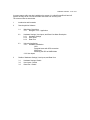
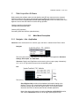
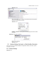
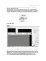
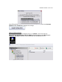
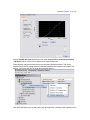
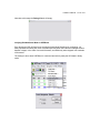
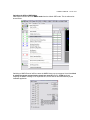
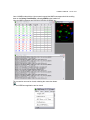
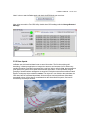
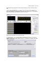
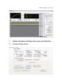
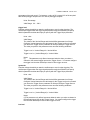
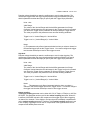
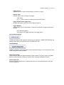
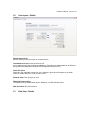
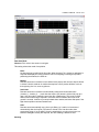
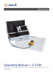
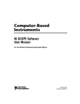
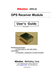
IceRadar2.0 Manual - 1 out of 31
IceRadar 2.0 – User Manual
ver 1.0
1
Introduction and foreword:
IceRadar was developed to assist glaciologists in performing radar surveys on icefields and
glaciers using portable and cost-effective equipment. IceRadar was developed by Blue System
Integration Ltd. (BSI) of Vancouver, B.C. Canada. www.bluesystem.ca - [email protected] 604.726.1817
IceRadar is a product developed with off-the-shelf hardware and customization in mind to
maximize the value it brings to its end-users. It is distributed as a product, including radar
transmitter, digitizer, computer, and software. As such, the system uses a pre-installed software
key that binds digitizer hardware and computer used for acquiring data. Should one of these
items be replaced, please contact BSI for obtaining a new key.
Feedback and additional specific requirements are welcome as this product remains
customizable.
The hardware, and in particular the computer that is used to run the application has been
selected to optimize portability, low pricing, and tolerance to shocks. The Asus eeePC was found
to fulfill these requirements. It is one of the smallest laptop available today, and while it is not a
ruggedized computer like the Toughbooks class of laptops, it is equipped with a solid state hard
drive (SSD) with no moving part. Once protected in a rugged box such as Pelican's the computer
will be protected from dust, rain, and shocks at a fraction of the price of a Toughbook.
It is important to note that on the eeePCs, the capacity of the solid-state-drive is significantly
smaller than the capacity found on today's desktop and laptop computers. This should be
addressed by:
– not installing additional software on the C: drive
– keeping Microsoft Windows updates disabled.
The eeePC laptop must be considered as a field instrument, and as such no other application
should run when IceRadar is operating.
Additionally, the laptop power settings were adapted to fieldwork. The computer will remain ON
even with a closed lid, and it will neither hibernate, nor go on standby. All these settings can be
changed, and as such, the user should be aware of the reasons behind them. Microsoft Windows'
look and feel was set for Best Performance, which is why the operating system does not
presents the standard Windows XP interface. To save battery life the wireless adapter was
disabled and turned off.
If a carrying case is used such as a Pelican box, make sure that the computer can cool off
reasonably well. On previous fieldwork, even though never an issue, the computer fan kicked in
at several occasions on a sunny day due to warming around the computer and the protective
case' s foam.
Securing the USB connectors in place is also something to keep in mind.
If you change time zone, do not forget to adjust the PC time as this may result in a different time
between the PC and the GPS. The main issue with time zone change is the GPS resetting itself.
In this case, the GPS has to be set back to NMEA mode and 57600 baud.
IceRadar2.0 Manual - 2 out of 31
A screen capture utility was also installed on the system. It is called ScreenPrint32 and will
capture an image of all or a user selectable area if the Prnt Scrn key is hit.
The content outline is show below.
1
Introduction and forewords
2
Data Acquisition Software
3
2.1
Main Menu Description
2.1.1 Navigate – Info – Application
2.2
Hardware Settings, User Inputs, and Data View Menu Description
2.2.1 Hardware Settings
2.2.2 User Inputs
2.2.3 Data View
2.3
Using the Application
2.3.1 Hardware Initialization
GPS
Potential issues with GPS connection
SiRFDemo
Switching the GPS to NMEA Mode
2.3.2 User Inputs
Details of Hardware Settings, User Inputs, and Data View
3.1
3.2
3.3
Hardware Settings -Details
User Inputs - Details
Data View - Details
IceRadar2.0 Manual - 3 out of 31
2
Data Acquisition Software
Before starting the software make sure both digitizer and GPS are connected to the computer.
Digitizer's power-up state can be checked with a green LED found at the back of the unit. It is
also recommended to use the semi circular strain relief groove found on the base plane of the
digitizer to secure the USB cable in its socket during operation.
Checking operation of the digitizer:
Use Max utility (described later)
Checking GPS operation
See setting GPS with SirfDemo (described later)
2.1
Main Menu Description
2.1.1 Navigate – Info - Application
Shortcuts: alt to activate,arrows to scroll left, right, and down a submenu then Enter to select
Navigate:
This menu gives accces to the three main views available in the application. Hardware
Settings, User Inputs, and Data View.
Shortcuts: PageUp and PageDown can be used to go from page to page. Alternatively
ctrl 1, ctrl 2, ctrl 3 give direct access to the corresponding page.
Info:
This menu gives access to the various helps available in the application.
Show Digitizer Help provides all the hardware information relating to the
digitizer. This is a very comprehensive Help that describes all the digitizer
hardware settings and the way the digitizer works. It is a general purpose
discussion and does not directly describe the IceRadar application.
Most of the relevant information is found in the Device--> NI 5132/5133 section,
and in the Fundamentals section of the NI High Speed Digitizers Help.
IceRadar2.0 Manual - 4 out of 31
Shortcuts: ctrl D
Show Context Help opens / closes a Context Help window with descriptions
relating to the object under the mouse.
Shortcuts: ctrl H
IceRadar... and BSI... are extra general information pop-ups as well as contact
information.
Application: This menu is as follows:
Exit: Exit the application.
Shortcuts: ctrl X
2.2
Hardware Settings, User Inputs, and Data View Menu Description
These are the three main windows available in the application. Within each of them, specific
functionality is accessed.
2.2.1 Hardware Settings
Shortcuts: ctrl 1
IceRadar2.0 Manual - 5 out of 31
The Hardware Settings window gives access to all the important digitizer hardware parameters.
Once these settings are done, they should normally not changed very often. Anytime a hardware
setting is changed, committing the settings is required via the Commit Setting (F10) button. If not
commit is done, the application will pop a message box.
2.2.2 User Inputs
Shortcuts: ctrl 2
The User Inputs window allows the user to input the Wave Parameters, notably the wave
IceRadar2.0 Manual - 6 out of 31
velocity in air, the wave velocity in ice, and the antenna spacing. Note that the wave
parameters are not saved to file .
This windows also is used to set which data file is going to be used, and which data Line is
being acquired. Next, the user can select two volumes or hard drives present on the system to
check their size comparatively to the data file. This is important for solid state HD-equipped
laptops like the eeePC because drive capacity is significantly smaller than today's rotating drives.
Finally, this window also provides the user with the full GPS reading parsed from the GAA NMEA
message.
2.2.3 Data View
Shortcuts: ctrl 3
The Data View window allows the user to follow the acquisition data as radargrams are being
acquired. The top left graph shows the relative position of the data Locations as read by the GPS.
Position is expressed in Lat Long and is given here solely as a rough guide of the Line trajectory
on the terrain. The radar signal graph shows a given radargram as it is been acquired by the
digitizer. If Stacking is enabled, the plot will flicker indicating several radargrams are being
acquired. However, during stacking, just a subset of the stacked data will be shown being
refreshed and once stacking si completedthe averaged data resulting from it will be shown.The
2D Profile graph shows a waterfall view of all the radargram acquired in the current Line.Times
are converted to depth based on the wave parameters previously entered. From this
windows,Stacking, Auto cycle Delay, Data Save Mode, GPS Data Capture can be set.
IceRadar2.0 Manual - 7 out of 31
Conceptually, a Location identify where a radargram is acquired. Logically, it is defined by a
position data set (from the GPS) and a radargram data set ( from the digitizer). A Location is
always part of one Line, and many Locations belong to a Line.
Additionally, the Browse function can be used to quickly view data acquired in other Lines and
Files. Because IceRadar is mainly an applications used to collect data, only basic line browsing
features are built-in.
2.3
Using the Application
2.3.1 Hardware Initialization
This is a two-step process. First, the GPS port is selected, followed by the digitizer initialization.
GPS:
In case no GPS serial port is shown in the drop down menu when the pop up opens, or if the
Prolific serial port does not show, just open the drop down and select Refresh.
The selected baud rate must match the GPS rate setting obtained with SiRFDemo. Do not
change this settings without first checking the port speed with SiRFDemo. SiRFDemo is
explained in the next section.
Note on GPS port selection:
Selecting the GPS only requires to pick the right
serial port used by the USB-serial driver. If the port
is not known, click Check Ports (Alternatively the
devmgmt.msc command can be run from the DOS
prompt). This will open the Device Manager and
will show the Prolific USB-to-Serial Comm Port,
in the Ports (COM & LPT) section, that is used by
the GPS. In the example below, the GPS is
operating via virtual serial port 4. Note that if no
GPS is connected to the computer, the Prolific
device will not appear.
Digitizer:
If the Digitizer device is properly connected to the
computer, it will show with its serial number.
IceRadar2.0 Manual - 8 out of 31
Once GPS and Digitizer are selected, set the hardware settings as required via the Hardware
Settings window. Commit any changes to the settings.
Notes on Digitizer selection:
Checking proper operation of the digitizer prior to run IceRadar, can be done with the
Measurements and Automation eXplorer (MAX),selecting the device under Devices and
Interfaces → NI-DAQmx Devices using the Self Test and Test Panels functions.
IceRadar2.0 Manual - 9 out of 31
Also the SCOPE Soft Panel application found under Program Files-->National Instruments
-->NI-Scope can be used to run the digitizer as a simple oscilloscope.
Virtual digitizers may also be listed if they were previously defined with MAX. This can be
beneficial to test the file saving features of IceRadar without actual hardware connected to the
digitizer. Your laptop will have a virtual device already defined.
Once GPS and Digitizer are up and running with the application, checking proper operation of the
IceRadar2.0 Manual - 10 out of 31
GPS is required.
Checking GPS Mode:
Click on Check GPS Mode will open the Test GPS window. If the GPS is set up properly,
updated GPS readings will scroll automatically as a result of slight GPS position changes (within
a few meters).
Proper GPS setting means that the Rikaline GPS must have been set with Disabled Static Mode
prior to run an acquisition at low speed, such as walking/skiing or low-speed skidoo.
If the Static Mode is enabled, the GPS will "freeze" the position at very low speed to cancel
out the drifting resulting from its intrinsic reading fluctuations. Position updates are then only
available when either the location changes by about 50m, or when an acceleration is detected.
The appropriate GPS settings should have been already checked with the SiRFDemo utility.
However, to make sure the settings are still maintained in the GPS, observing the GPS reading in
the GPS String Tab of the Test GPS Reading pop-up will confirm GPS proper operation. After a
few seconds, the GPS String should update every few seconds following a slight change in
position (a few meters) and the Changed Detected message should appear with the new GPS
data string. If the GPS failed to be set on the Disabled Static Mode, no position update with the
Change Detected footer will appear. Only a Manual Poll (F1) will produce a reading.
If this is the case, the GPS “Disabled Static Mode” must be activated (that is Static Mode
disabled). It is explained at the end of the section detailing PotentialIssues with the GPS
connection.
IceRadar2.0 Manual - 11 out of 31
Potential issues with GPS connection
It is possible that the Test GPS Reading returns and error like on the example above. This can
happen when the GPS is left turned OFF for a long period of time, or when its current
geographical location is significantly different from the last location the GPS was operating at. If
this is the case, Stop the Test GPS Reading utility, exit IceRadar, and launch SiRFDemo.
SiRFDemo
SiRFDemo is an utility provided by the GPS chip manufacturing company. This product is
independent of IceRadar, and its operation is summarized below.
At launch, SiRFDEMO will open and immediately show a Data Source Setup pop up with Serial
Port and Baud rate settings. Select the port where the GPS is located, and set the speed to
IceRadar2.0 Manual - 12 out of 31
57600 baud.
Next, open the connection to the GPS device by clicking on the following icon:
The next step requires to Synchronize the Protocol and Baud Rate. It is done as shown below.
While the synchronization is taking place the top of SiRFDemo windows shows the sequencing of
baud rates, until the system settles down on the correct one. This operation sometimes does not
recognize the firmware on the GPS chip and it needs to be repeated a few times.
Following the synchronization, the Signal View should show that the GPS is reading properly.
On the example below, 7 satellites were found, 4 of them giving strong (green) signal.
IceRadar2.0 Manual - 13 out of 31
Note that at this stage the Debug View is still empty.
Verifying Disabled Static Mode in SiRFDemo
Even though the GPS will have been set with the Static Mode Disabled prior to shipping, it is
always possible the setting will revert to Enable especially when the instrument changes location
between usages, in the order of several kilometers, and definitively when shipped over hundreds
of kilometers.
The settings is done when SiRFDemo is connected and actively ready the GPS data in binary
mode.
IceRadar2.0 Manual - 14 out of 31
Switching the GPS to NMEA Mode
Next step is to set the GPS into NMEA mode from the default SiRF mode. This is achieved as
shown below:
Switching to NMEA Protocol will first cause the NMEA Setup pop up to appear. Here it is critical
to select the correct communication speed one more time, that is, 57600 baud rate.
Selecting the NMEA message is not important here, as this will be done automatically by the
IceRadar application.
IceRadar2.0 Manual - 15 out of 31
Once in NMEA mode with the right connection speed the NMEA messages should be scrolling
down on the Debug View Window, indicating NMEA on the header bar.
Here the NMEA messages are $GPGGA, $GPGSA, $GPRMC etc...
The connection can now be closed, releasing the connection button.
And the SiFRDemo application can be closed
IceRadar2.0 Manual - 16 out of 31
Now it is time to start IceRadar again and check the GPS Mode one more time.
After a few seconds the Test GPS Utility should show GPS readings with the Change Detected
Message.
2.3.2 User Inputs
IceRadar uses a hierarchical data format to store information. The file format being selfdescribing, it allows an application to interpret the structure and contents of a file without any
outside information. Data are first grouped into a top level object, called a Line, that represents a
given path on the glacier where point measurements were taken. A Line represents a logical
grouping of locations where radargrams are acquired. Each point measurement within a Line is
linked to a subgroup object called a Location. This object is in turn linked to the radar data, the
GPS data, later the calculated depth data. All these objects can have attributes (Meta data)
associated to them. All the data is consolidated into the hierarchical file system, and can be
accessed by the analysis routines.
IceRadar2.0 Manual - 17 out of 31
Typically, a given glacier survey would be associated with a data file. Each survey line would be a
Line in the file system domain, and each points where data is gathered along the Line would be a
Location containing Radargram and GPS data at first, and later picked data defining the depth.
Additional survey lines would be associated to additional file system Lines.
This data organization can be adapted to users' need. Each line could be a single file. However
with this model, one would loose the benefit of not having to manage numerous files.
Now it is time to select/create a data file. Use the Open/Create New File button to do so.
Second, a Line must be created or chosen amongst already existing Lines :
IceRadar2.0 Manual - 18 out of 31
The above pop up will allow to create a first Line in a new file (line_0). Lines have a system
name that cannot be changed, a given name that is user-defined, and a comments attribute.
Hit Create Line to create a new line. The new active line can be seen at the top of the Data View
window above the radargram graph object.
Checking disk space is recommended. First use the drop down to choose up to two volumes or
hard drives on the computer.
Second, click on Check (Ctrl F4) to check the data file size.
IceRadar2.0 Manual - 19 out of 31
Each data file can be composed of as many Lines as necessary. We are now ready to acquire
data.
Select the Data Save Mode (F9), first to None to check the readings, and hit Acquire a few
times to start building a 2D representation of the data. In the example below, a virtual digitizer is
being used and therefore the radargram produced is a sine wave.
All the modes of acquisition are now ready to be used.
If the Manual Mode is used, a Create / Select Location pop-up will appear to describe the
Location. Similarly to the Create / Select Line pop-up, a Location has a system name, given
name, and description.
IceRadar2.0 Manual - 20 out of 31
It is recommended to give a Location a user name for any specific locations of interest such as a
survey pole, the beginning of a survey line, last point of a survey line etc... For more standards
Location, running in Auto Mode is recommended.
Stacking
Shortcut:F7 to select
Stacking allows to average the indicated number of traces before saving. Discrete values are
allowed: 1, 25, 50, 100, 256
Auto cycle Delay (s)
Shortcut: F8 to select
Specifies how many seconds to wait between acquisitions.
It is important to keep in mind that with the NI-5132/5133, the stacking is software-timed between
trigger events. Acquiring a triggered radargram is first done in the digitizer's on-board memory.
The data is then fetched into computer RAM via USB. Then the digitizer waits for the next
available trigger to acquire a new data set. GPS communication is run in a separate thread to
limit overhead.
When Stacking is set at 100 or more, the Auto-Cycle Delay can be set to 0, which will lead to an
effective sampling rate of as low as about 2 seconds. When Stacking is set to 50 or less, the
Auto-Cycle Minimum setting is 1 second which will lead to an effective sampling rate as low as 1
to 2 seconds. This limitation has been implemented to insure low overhead on the processors to
increase reliability and insure the application can acquire data on Auto for hours at a time (we are
still running Windows after all !).
Future releases of National Instruments USB Digitizers will likely include more advanced
hardware capabilities which can be implemented in future versions of IceRadar.
Quick Data Browsing
To quickly check data that were previously acquired, it is possible to select a Line that was
already acquired and to display its data with the Show Line 2D Profile button.
Then, as shown on the image below, selecting the Browse option will allow the selection of a
specific location and browse amongst its associated radargram as referenced by its location
number. This number corresponds to the x-axis of the 2D graph.
Note that the 2D graph scale can be changed by clicking on the first and last number of the scale
and typing the new scale limit value.
IceRadar2.0 Manual - 21 out of 31
3
Details of Hardware Settings, User Inputs, and Data View
3.1
Hardware Settings -Details
IceRadar2.0 Manual - 22 out of 31
Vertical
vertical range
Pass the value of the input range the oscilloscope uses for the channel. For example, to
acquire a sine wave that spans between -5.0 and 5.0 volts, pass 10.0 as the value of this
parameter.
Units: Volts
Valid Range:
Check the Hardware User's Manual for a device's list of supported vertical
ranges. If the specified range is not supported by a device, the value will be
coerced up to the next valid range.
vertical offset
Pass the location of the center of the range that you specify with vertical range. Express
the value with respect to ground. For example, to acquire a sine wave that spans
between -5.0 and 5.0 volts pass 0 as the value, or for a sine wave that spans between
0.0 and 10.0 volts, pass 5.0 as the value and set Vertical Range to 10.0 volts.
Units: Volts
Valid Values:
vertical coupling:
The NI 5132/5133 has software selectable AC, DC, and GND coupling. Select AC
coupling if the input signal has a DC component that you want to reject, provided you are
not concerned about low-frequency flatness. A DC input adjustment is available if you do
IceRadar2.0 Manual - 23 out of 31
not want to enable AC coupling. Ground coupling internally connects the input to the local
ground.
Channel
maximum input frequency
Specify the bandwidth of the channel expressed as the
frequency at which the input circuitry attenuates the input signal by 3 dB.
The NI 5132/5133 has a software selectable 20 MHz noise filter that limits the bandwidth
of the signal path. The filter is intended to reduce noise when the input signal content is
20 MHz or less.
Units: Hertz
Valid Values:
20Mhz; 50Mhz (no filtering). If the signal is not noisy (EM noise), the no filtering option is
recommended as the 20Mhz filter somewhat attenuates the air waves in the upper part of
its spectrum.
Horizontal
sample rate
Specify the sampling rate for the acquisition.
Units: Hertz (Samples / Second)
Valid Range:
The combination of sampling rate and min record length must allow the scope to
sample at a valid sampling rate for the acquisition type specified in NI-Scope
Configure Acquisition and not require more memory than the onboard memory
module allows.
record length
Pass the minimum number of points you require in the record for each channel. Call
niScope Actual Record Length after the acquisition has been initiated to obtain the actual
record length used.
Valid Values: 1 - available onboard memory
Trigger
IceRadar2.0 Manual - 24 out of 31
Trigger type
Pass the type of trigger you want the oscilloscope to use and then call the appropriate VI
to completely configure the trigger.
Valid Values:
Edge
Configures the oscilloscope for edge triggering. An edge trigger occurs when the
trigger signal crosses the trigger level specified with the set trigger slope. You
configure the trigger level and slope with niScope Configure Edge Trigger.
Hysteresis
Configures the oscilloscope for hysteresis triggering. A hysteresis trigger occurs
when the trigger signal crosses the trigger level with the specified slope and
passes through the hysteresis window you specify. You configure the trigger
level, slope, and hysteresis with niScope Configure Hysteresis Trigger.
Digital
Configures the oscilloscope for digital triggering. A digital trigger occurs when the
trigger signal has the the specified slope. You configure the trigger slope with
niScope Configure Digital Trigger.
Window
Configures the oscilloscope for window triggering. A window trigger occurs when
the trigger signal enters or leaves the window defined by the values you specify
with the Low Window Level, High Window Level, and Window Mode parameters.
You configure the window with niScope Configure Window Trigger.
trigger delay
Pass the length of time you want the digitizer to wait after it detects the trigger before it
marks the Reference Position.
Units: Seconds
reference position
When the oscilloscope detects a trigger, it waits the length of time you specify with the
Trigger Delay parameter of niScope Configure Trigger Source and marks this spot as the
Reference. This parameter sets where this Reference is positioned in a record as a
IceRadar2.0 Manual - 25 out of 31
percentage of the total record. For instance, a value of 25.0 means 25% of the acquired
data will be pretrigger samples and 75% will be posttrigger samples.
Units: Percentage
Valid Range: 0.0 – 100.0
trigger level
Pass the voltage threshold you want the oscilloscope to use for edge triggering. The
oscilloscope triggers when the trigger signal passes through the threshold you specify
with this parameter and has the slope you specify with the Trigger Slope parameter.
Units: volts
Valid Range:
The values of the Vertical Range and Vertical Offset parameters in niScope
Configure Vertical determine the valid range for the Trigger Level on the channel
you use as the Trigger Source parameter in niScope Configure Trigger Source.
The value you pass for this parameter must meet the following conditions.
Trigger Level <= Vertical Range/2 + Vertical Offset
Trigger Level >= (-Vertical Range/2) + Vertical Offset
Notes:
(1)
This parameter only affects instrument behavior when you select a
channel or the external trigger input as the Trigger Source. You cannot configure
the trigger level that the oscilloscope uses for other trigger sources.
hysteresis
Pass the voltage threshold you want the oscilloscope to use for edge triggering. The
oscilloscope triggers when the trigger signal passes through the threshold you specify
with this parameter and has the slope you specify with the Trigger Slope parameter.
Units: volts
Valid Range:
The values of the Vertical Range and Vertical Offset parameters in niScope
Configure Vertical determine the valid range for the Trigger Level on the channel
you use as the Trigger Source parameter in niScope Configure Trigger Source.
The value you pass for this parameter must meet the following conditions.
Trigger Level <= Vertical Range/2 + Vertical Offset
Trigger Level >= (-Vertical Range/2) + Vertical Offset
Notes:
(1)This parameter only affects instrument behavior when you select a channel or
the external trigger input as the Trigger Source. You cannot configure the trigger
level that the oscilloscope uses for other trigger sources.
low level
IceRadar2.0 Manual - 26 out of 31
Pass the voltage threshold you want the oscilloscope to use for edge triggering. The
oscilloscope triggers when the trigger signal passes through the threshold you specify
with this parameter and has the slope you specify with the Trigger Slope parameter.
Units: volts
Valid Range:
The values of the Vertical Range and Vertical Offset parameters in niScope
Configure Vertical determine the valid range for the Trigger Level on the channel
you use as the Trigger Source parameter in niScope Configure Trigger Source.
The value you pass for this parameter must meet the following conditions.
Trigger Level <= Vertical Range/2 + Vertical Offset
Trigger Level >= (-Vertical Range/2) + Vertical Offset
Notes:
(1) This parameter only affects instrument behavior when you select a channel or
the external trigger input as the Trigger Source. You cannot configure the trigger
level that the oscilloscope uses for other trigger sources.
high level
Pass the voltage threshold you want the oscilloscope to use for edge triggering. The
oscilloscope triggers when the trigger signal passes through the threshold you specify
with this parameter and has the slope you specify with the Trigger Slope parameter.
Units: volts
Valid Range:
The values of the Vertical Range and Vertical Offset parameters in niScope
Configure Vertical determine the valid range for the Trigger Level on the channel
you use as the Trigger Source parameter in niScope Configure Trigger Source.
The value you pass for this parameter must meet the following conditions.
Trigger Level <= Vertical Range/2 + Vertical Offset
Trigger Level >= (-Vertical Range/2) + Vertical Offset
Notes:
(1)
This parameter only affects instrument behavior when you select a
channel or the external trigger input as the Trigger Source. You cannot configure
the trigger level that the oscilloscope uses for other trigger sources.
trigger coupling
The trigger coupling parameter can be either AC, DC, HF Reject, LF Reject, or AC Plus
HF Reject. This parameter works much like the vertical coupling parameter. When AC
is selected, NI-SCOPE rejects the DC component of the trigger signal. When triggering
on channel 0 or channel 1 of the digitizer, the input signal is immediately coupled based
on the vertical coupling parameter. Therefore, if the vertical coupling parameter is set
to AC coupling, triggering occurs on the AC components of the signal because the DC
component has already been removed.
IceRadar2.0 Manual - 27 out of 31
Trigger source
Pass the source you want the oscilloscope to monitor for a trigger.
Channel name
Pass the channel name you want to configure.
Valid Values:
0..n-1, n is the number of channels on the NI SCOPE device
Trigger window mode, trigger slope
All these descriptions can be found in the Digitizer Help File.
Trigger Modifier:
Configures the device to automatically complete an acquisition if a trigger has not been
received.
None: Normal triggering.
Auto Trigger: Auto trigger acquisition if no trigger arrives.
Clear Hardware Settings
CLEAR HW releases all the acquisition settings from the hardware. COMMIT SETTINGS have to
be done before starting a new acquire once a CLEAR HW is sent.
Commit Settings
COMMIT CHANGES, commit to hardware all the acquisition settings, so once the hardware runs,
all the settings are already uploaded.
actual record length:
Actual number of points the digitizer acquires for each channel. The value is equal to or greater
than the minimum number of points you specify with a horizontal configuration function.
actual sample rate:
Returns the effective sample rate, in samples per second, of the acquired waveform using the
current configuration
IceRadar2.0 Manual - 28 out of 31
3.2
User Inputs - Details
Open/Create new file
Browse directory structure to open or create a new file.
Create/Select new line Create or Select a Line.
A Line represents a logical grouping of radargrams. Typically a pre-defined path will be followed,
along which radar data will be acquired. All this data will belong to a Line.
Check File space
Check two user selectable volumes for size. Warning is given when the space left on either
volume is smaller than 25% of the current file size.
Show tip strips Turn tip strips on or off.
Enable GPS data capture
GPS data saving is enabled when active. Otherwise, no GPS data are saved.
GPS Serial Port GPS Port selection
3.3
Data View - Details
IceRadar2.0 Manual - 29 out of 31
l
Data Save Mode
Shortcut: F9 to select, then arrows to navigate
This setting selects the mode of acquisition.
None:
No data savings is performed in this mode. When Acquire (F4) is clicked, a radargram is
acquired and displayed. Use this mode to check if everything is working as expected,
positioning the antenna, the GPS etc...
Manual:
Data are saved and a Location is user-defined via a pop-up each time the Acquire button
is clicked. Use this mode at a Location that requires a more precise definition, such as
the beginning of a Line, a survey pole etc..
Semi-Auto:
Data are saved and a Location is automatically created with incremental name
(Location_1, Location_2, …) each time the Acquire (F4) button is clicked. No pop up is
open. Use this mode to manually control the rate of data saving. This mode is useful
when some maneuvering is required in crevasse area for instance where not much
ground is covered. It allows to just acquire data when needed, and save disk space if the
high data acquisition rate was instead used.
Auto:
Data are saved automatically every Auto cycle Delay (s), Location is incremented
automatically after the Acquire (F4) button is clicked once. Use this mode when
progression along a Line is steady. Once the acquisition is on-going check once in a
while the radargram as they are acquired, the GPS readings, and the file size.
Stacking
IceRadar2.0 Manual - 30 out of 31
Shortcut:F7 to select
Stacking allows to average the indicated number of traces before saving. Discrete values are
allowed: 1, 25, 50, 100, 256
Auto cycle Delay (s)
Shortcut: F8 to select
Specifies how many seconds to wait between acquisitions.
It is important to keep in mind that with the NI-5132/5133, the stacking is software-timed between
trigger events. Acquiring a triggered radargram is first done in the digitizer's on-board memory.
The data is then fetched into computer RAM via USB. Then the digitizer waits for the next
available trigger to acquire a new data set. GPS communication is run in a separate thread to
limit overhead.
When Stacking is set at 100 or more, the Auto-Cycle Delay can be set to 0, which will lead to an
effective sampling rate of as low as about 2 seconds. When Stacking is set to 50 or less, the
Auto-Cycle Minimum setting is 1 second which will lead to an effective sampling rate as low as 1
to 2 seconds. This limitation has been implemented to insure low overhead on the processors to
increase reliability and insure the application can acquire data on Auto for hours at a time (we are
still running Windows after all !).
Future releases of National Instruments USB Digitizers will likely include more advanced
hardware capabilities which can be implemented in future versions of IceRadar.
Enable GPS data capture
Shortcut: F1
If selected, the GPS data will be saved with the radar data.
GPS Single Read
Check GPS by reading position once.
Shortcut: F12
Performs one GPS read. No data saving are associated with this action.
Radar Signal Auto Scale
Auto Scale Radargram
ShowLine2DProfile
Retrieve all data in a Line and plot radargrams data with color scaling versus time generating a
2D color plot
Browse
Shorcut: ctrl F10
Enables the Location drop down and acquired data browsing.
When Browse is enables, no acquisition can be performed.
Similarly, acquisition must no be running for this control to be accessible.
Location
Shorcut: ctrl F12
IceRadar2.0 Manual - 31 out of 31
When Browse box is selected, this drop-down allows the user to select a Location and display its
radargram. All datagrams in a Line must have been retrieved first on the waterfall plot for being
accessible.
Color Scale
Color scale for the waterfall plot. Make sure Interpolate Color remains selected in the color scale.
Approx. Horiz. Scale (m/div)
Single radargram plot scale. This gives an approximation on the depth equivalent time read on
the plot
Digitizer Horizontal Span Equivalent Ice Depth (m)
Single radargram plot approximate span. This gives an approximation on the depth equivalent
time read on the plot.
Missed some triggers?
If triggers are missed, the stacking data remains valid as the actual number of triggered
radargrams is used in the stacking computation.