1
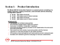
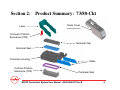
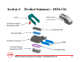
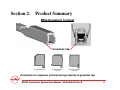
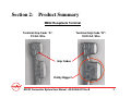
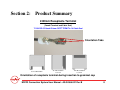
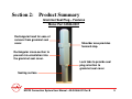
MX123 Connection System
User Manual
Revision B – October 22, 2009
Table of Contents
Section 1:
Section 2:
Section 3:
Section 4:
Section 5:
Section 6:
Section 7:
Section 8:
Section 9:
Section 10:
Section 11:
Product Introduction
Product Summary
Harness Assembly Instructions
Connector Mating Instructions
Service Instructions
Electrical Continuity Checking
Tool Ordering Information
Revision History
Files
Appendix A - Document Change History
Appendix B - Cleaning Instructions
MX123 Connection System User Manual - AS-34566-001 Rev B
2
Section 1: Product Introduction
The Molex MX123 Connection System is a sealed system consisting of a
header/controller, mating connectors, and terminals with the following
configuration options:
A.
B.
C.
D.
80-Ckt ~ (80) 0.64mm terminals
73-Ckt ~ (72) 0.64mm and (1) 2.8mm terminals
56-Ckt ~ (56) 0.64mm terminals
49-Ckt ~ (48) 0.64mm and (1) 2.8mm terminals
HIGHLIGHTS:
This system has multiple keying options.
Ground blade engages before signal pins contact.
Connector is friendly to “blind-mate” conditions.
Connector provides temporary retention to the header before the cam assist
lever arm is activated.
Cam assist lever arm remains in pre-lock position until the harness
connector is in pre-lock position on the header/controller.
CPA remains in pre-lock position until cam assist lever arm is locked closed.
Available with molded-in grommet seal plugs for harness customization.
MX123 Connection System User Manual - AS-34566-001 Rev B
3
Section 2: Product Summary: 73/80-Ckt
Lever
Dress Cover
(Shipped Separately)
Connector Position
Assurance (CPA)
Grommet Cap
Grommet Seal
Connector Housing
Slides
Terminal Position
Assurance (TPA)
Perimeter Seal
MX123 Connection System User Manual - AS-34566-001 Rev B
4
Section 2: Product Summary: 49/56-Ckt
49/56-Ckt Exploded View
Lever
Dress Cover
(Shipped Separately)
Connector Position
Assurance (CPA)
Grommet Cap
Grommet Seal
Connector Housing
Slides
Terminal Position
Assurance (TPA)
Perimeter Seal
MX123 Connection System User Manual - AS-34566-001 Rev B
5
Section 2: Product Summary
MX64 Receptacle Terminal
Orientation Tab
Correct Orientation
90° Misorientation
Lock-out
180° Misorientation
Lock-out
Orientation of receptacle terminal during insertion to grommet cap
MX123 Connection System User Manual - AS-34566-001 Rev B
6
Section 2: Product Summary
MX64 Receptacle Terminal
Terminal Grip Code “A”:
22 GA. Wire
Terminal Grip Code “B”:
18/20 GA. Wire
Grip Codes
Visibly Bigger!
MX123 Connection System User Manual - AS-34566-001 Rev B
7
Section 2: Product Summary
2.80mm Receptacle Terminal
(Yazaki Terminal and Cable Seal)
7116-4152-02 Yazaki 2.8mm RCPT TERM Tin 14 Cable Seal
Orientation Tabs
Correct Orientation
90°Misorientation
Lock-out
180°Misorientation
Lock-out
Orientation of receptacle terminal during insertion to grommet cap
MX123 Connection System User Manual - AS-34566-001 Rev B
8
Section 2: Product Summary
Grommet Seal Plug – Features
Molex Part 34586-0001
Rectangular head for ease of
removal from grommet seal
cover.
Shoulder area provides
forward stop.
Rectangular cross-section to
prevent mis-orientation into
the grommet seal cover.
Lock tabs to provide seal
plug retention to
grommet seal cover.
Sealing surface
MX123 Connection System User Manual - AS-34566-001 Rev B
9
Section 2: Product Summary
73/80-Ckt “As Shipped”
49/56-Ckt “As Shipped”
Harness connector
assembly shipped with TPA
& lever in pre-lock position.
Lever will remain in pre-lock
until mated with
header/controller, or a force
over 190N is achieved.
If lever moves freely from
pre-lock position without
being mated to
Header/Controller:
Do Not Use Connector!
Dress Cover Shipped
Separately.
MX123 Connection System User Manual - AS-34566-001 Rev B
10
Section 3: Harness Assembly Instructions
A.
TPA shown in “As Shipped” position
TPA to remain in pre-lock position (as shipped) until all terminals are loaded
(Figs. 3-1 and 3-2). TPA is not to be removed from connector!
Fig. 3-1
Fig. 3-2
5.0mm
TYP.
Section View
Views of TPA in “Pre-Lock” Position
MX123 Connection System User Manual - AS-34566-001 Rev B
11
Section 3: Harness Assembly Instructions
B. Connector Circuit Locations
WIRE BUNDLE SIDE
20
19
18
17
16
15
14
13
12
11
10
9
8
7
6
5
4
3
2
1
40
60
39
59
38
58
37
57
36
56
35
55
34
54
33
53
32
52
31
51
30
50
29
49
28
48
27
47
26
46
25
45
24
44
23
43
22
42
21
41
80 way Molex
Wire tie area
80-Ckt
80
79
78
77
76
75
74
73
72
71
70
69
68
67
66
65
64
63
62
61
WIRE BUNDLE SIDE
16
15
14
13
12
11
10
9
8
7
6
5
4
3
2
1
52
51
73
50
49
32
48
31
47
30
46
29
45
28
44
27
43
26
42
25
41
24
40
23
39
22
38
21
37
20
36
19
35
18
34
17
33
73 way Molex
Wire tie area
73-Ckt
72
71
70
69
68
67
66
65
64
63
62
61
60
59
58
57
56
55
54
53
WIRE BUNDLE SIDE
14
13
12
11
10
9
8
7
6
5
4
3
2
1
28
42
56
27
41
55
26
40
54
25
39
53
24
38
52
23
37
5
22
36
50
21
35
49
20
34
48
19
33
47
18
32
46
17
31
45
16
30
44
56 way Molex
15
29
43
Wire tie area
56-Ckt
WIRE BUNDLE
SIDE SHOWN
MX123 Connection System User Manual - AS-34566-001 Rev B
12
Section 3: Harness Assembly Instructions
C. Terminal Installation
For ease of assembly, it is recommended that when populating the
connector, wires be populated in the following manner (see Fig 3-3): 1) Fully
populate down Column 1 and then 2) continue on to Column 2 and so forth
until the entire connector is populated. Refer to Fig 3-4 for proper terminal
orientation.
Fig. 3-4
Fig. 3-3
Column1
Column2
0.64mm Orientation
Align terminal orientation tab
with slot in grommet cap
opening to install the terminal
Orientation Tab
MX123 Connection System User Manual - AS-34566-001 Rev B
13
Section 3: Harness Assembly Instructions
C. Terminal Installation (continued)
With TPA still in pre-lock position, orient terminal to rear of connector.
Grip the wire (Fig. 3-5) and insert terminal through appropriate circuit
opening (Fig. 3-6). If resistance is encountered, retract the terminal and
adjust the angle of insertion. Continue inserting the terminal until it stops
and locks up on the lock finger with an audible click. Tug slightly on wire to
ensure terminal is locked.
Fig. 33-5
Fig. 33-6
MX123 Connection System User Manual - AS-34566-001 Rev B
14
Section 3: Harness Assembly Instructions
D. Wire Dressing Method
After inserting a terminal, bend the wire as close to the grommet cap as
possible and position as shown below. Continue populating terminals as
necessary.
1
2
3
4
5
6
MX123 Connection System User Manual - AS-34566-001 Rev B
15
Section 3: Harness Assembly Instructions
E. Grommet Seal Cover - Knockout Patterns
* Molded-in or single grommet seal plugs are used to seal unused circuit locations.
NOTE! Molded-in grommet seal plug knockout patterns will vary based on
application specific circuit locations. Single grommet seal plugs may still need to
be used to seal circuits without molded-in seal plugs.
Cavities Open For Circuits
Molded-in grommet seal plugs
MX123 Connection System User Manual - AS-34566-001 Rev B
16
Section 3: Harness Assembly Instructions
F. Grommet Seal Plug Installation
Step 1: Orient seal plug to the
opening in the grommet cap. Plug
should not be installed when
rotated 90 degrees from proper
orientation.
Step 2: Hold head of seal plug
securely to prevent rotation
during assembly.
Step 3: Push seal plug until it
locks into position into the
grommet cap.
Step 4: Verify that seal plug
shoulder is flush with grommet
cap as shown in cavities 33 and
53.
MX123 Connection System User Manual - AS-34566-001 Rev B
17
Section 3: Harness Assembly Instructions
G. TPA - Seating
With the terminals fully installed, the TPA can be seated into its final lock
position by applying an even force to both ends (Fig. 3-7) until it comes to a
stop (Fig. 3-8). If the TPA resists, it may be detecting a partially installed
terminal. Pull the TPA back into its pre-lock position and make sure all
terminals are fully seated. Upon completion, the TPA can be seated.
Fig. 3-7
Fig. 3-8
MX123 Connection System User Manual - AS-34566-001 Rev B
18
Section 3: Harness Assembly Instructions
H. Wire Bundle Dressing
After seating the TPA, insert a tie-wrap around the connector (Fig. 3-9) and
around the wire bundle as shown (Fig. 3-10).
While clasping the wire bundle and connector firmly, tighten the tie-wrap
securely around the bundle using an appropriate tie-wrap gun to meet the
specifications listed in Table 1 (next page) and shown in Fig. 3-11 and Fig. 312 (next page).
Fig. 3-9
Fig. 3-10
MX123 Connection System User Manual - AS-34566-001 Rev B
19
Section 3: Harness Assembly Instructions
H. Wire Bundle Dressing (continued)
Table 1: Dress Cover part numbers
Fig. 3-11
GM Part No.
Molex Part No.
Description
Height (H)
Width (W)
12582676
34565-0003
73/80 Ckt
≤ 44 mm
≤ 24 mm
12582679
34575-0003
49/56 Ckt
≤ 43 mm
≤ 24 mm
Fig. 3-12
H
W
Wire Bundle Height and Width Specifications
MX123 Connection System User Manual - AS-34566-001 Rev B
20
Section 3: Harness Assembly Instructions
I. Dress Cover Installation
After tie-wrapping the wire bundle, install dress cover by inserting the front
of the dress cover into the connector housing (Fig. 3-13) and pushing the
opposite end (Fig. 3-14) until it snaps into position. Fully seated dress cover
and TPA can be verified by ensuring MAX. height dimension (Fig. 3-14).
Fig. 3-13
Fig. 3-14
47.8mm
MAX.
Top of dress cover to bottom
of fully seated TPA
Step 1: Insert front end into housing.
Step 2: Press down to lock position.
MX123 Connection System User Manual - AS-34566-001 Rev B
21
Section 4: Connector Mating Instructions
A. Harness Connector To Header/Controller Color Identification
The harness connector TPA will be color-coded to match the appropriate
controller header (Fig. 4-1).
Fig. 4-1
TPA
Header/Controller
MX123 Connection System User Manual - AS-34566-001 Rev B
22
Section 4: Connector Mating Instructions
B. Harness Connector to Header/Controller Installation Into Pre-Lock
Correctly orient the harness connector (align keying features) onto the
controller connector (Fig. 4-2). Grip the top of the harness connector and
evenly push the connector downward until the lever moves slightly forward
(Fig. 4-3).
Fig. 4-2
Fig. 4-3
Align
Keying
Features
Align Keying Features
MX123 Connection System User Manual - AS-34566-001 Rev B
23
Section 4: Connector Mating Instructions
Caution!
Installing the harness
connector at an extreme
angle (see fig 4- 4 ) may
result in seal “scooping”
creating an environment
for fluid ingress.
Damage to the header, or
connector is possible if
excessive force is used.
Fig. 4- 4
MX123 Connection System User Manual - AS-34566-001 Rev B
24
Section 4: Connector Mating Instructions
C. Harness Connector to Header/Controller Mating To Final Lock
To begin mating the harness connector to the header/controller, place the
palm of your hand on the face of the lever. Push back the connector lever
towards the wire bundle to engage the harness connector to the controller
header (Fig. 4- 5). Mating force should be smooth and continuous. If not,
remove the connector and repeat step B.
Continue to rotate the lever arm (Fig. 4- 6).
Fig. 4-5
Fig. 4-6
MX123 Connection System User Manual - AS-34566-001 Rev B
25
Section 4: Connector Mating Instructions
C. Harness Connector to Header/Controller Mating To Final Lock (continued)
Continue to rotate the lever until you hear the primary latch click into final lock
over dress cover primary latch (Fig. 4-7a and 4-7b).
Fig. 4-7a
Fig. 4-7b
Dress Cover Primary Latch
Primary Latch Engaged
MX123 Connection System User Manual - AS-34566-001 Rev B
26
Section 4: Connector Mating Instructions
D. Connector Position Assurance (CPA)
Fig. 4-8
With the harness connector lever arm in its latched position, the CPA can
now be engaged. Push the CPA toward the wire bundle (Fig. 4- 8) until it
clicks into its final locked position (Fig. 4-9).
Fig. 4- 9
MX123 Connection System User Manual - AS-34566-001 Rev B
27
Section 5: Service Instructions
NOTE: For soiled or in-service ECM’s, please refer to Section 11 (Appendix B):
Cleaning Instructions prior to commencing the following procedures.
A. Harness Connector Removal From Module
To un-mate the harness connector from the header/controller, push the CPA
away from the wire bundle. Depress the primary latch on the top of the
harness connector so the lever arm releases from the harness connector
(Fig. 5-1).
Primary Latch
Fig. 5-1
MX123 Connection System User Manual - AS-34566-001 Rev B
28
Section 5: Service Instructions
A. Harness Connector Removal From Module (continued)
Push the top of the mate lever arm away from wire bundle using the palm of
your hand (Fig. 5-2).
Continue to rotate the lever until the connector lifts into pre-lock (Fig. 5-3).
The lever MUST be in the pre-lock position or the connector can not be easily
removed from the module. The lever must be fully forward for the harness
connector to be in pre-lock position.
Fig. 5-2
Fig. 5-3
MX123 Connection System User Manual - AS-34566-001 Rev B
29
Section 5: Service Instructions
A. Harness Connector Removal From Module (continued)
While pushing forward on the lever, grip the back of the harness and evenly
pull straight upwards and away from the module (Fig. 5-4).
Fig. 5-4
1
2
MX123 Connection System User Manual - AS-34566-001 Rev B
30
Section 5: Service Instructions
B. Dress Cover Removal
With the harness connector removed from header/controller (Fig. 5-5),
unlatch the dress cover latch features on each side of the dress cover guide
(Fig. 5-6). A small screwdriver or similar tool can be used to release the
latches.
Fig. 5-5
Fig. 5-6
Latch Feature
on each side
MX123 Connection System User Manual - AS-34566-001 Rev B
31
Section 5: Service Instructions
B. Dress Cover Removal (continued)
Fig. 5-7
With the dress cover latch features unlatched, insert your finger into dress
cover (Fig. 5-7) and pull up and away from the wire bundle. The dress cover
can be completely removed at this point (Fig. 5-8).
Fig. 5-8
MX123 Connection System User Manual - AS-34566-001 Rev B
32
Section 5: Service Instructions
C. Tie-Wrap Removal
The tie-wrap can now be removed from the wire bundle (Fig. 5-9) for easier
access to the wire to be serviced. The tie-wrap MUST be cut under the wire
dress tab to prevent damage to the wires!
Fig. 5-9
Do not cut near wires!
MX123 Connection System User Manual - AS-34566-001 Rev B
33
Section 5: Service Instructions
D. TPA Servicing
TPA should never be removed from the connector.
Step 1: Insert a small (2.0mm maximum) flat blade screwdriver into the TPA
service hole at one end of the connector (Fig. 5-10) and pry up. The TPA will
stop when it reaches its pre-lock position for terminal servicing.
Step 2: On the other end of the TPA, repeat Step 1 (Fig. 5-11) until the TPA
reaches its pre-lock position at both ends of the harness connector.
Approximate TPA travel will be 5.0mm (See Figs. 5-12 and 5-13 on next page).
Fig. 5-10
Fig. 5-11
1 2
Step 1: Pry up TPA
Step 2: Pry up opposite end of TPA
MX123 Connection System User Manual - AS-34566-001 Rev B
34
Section 5: Service Instructions
D. TPA Servicing (continued)
Fig. 5-12
Fig. 5-13
5.0mm
5.0mm
Views of TPA in “Pre-Lock” Position
MX123 Connection System User Manual - AS-34566-001 Rev B
35
Section 5: Service Instructions
E. MX64 Receptacle Terminal Removal
Ensure TPA is in pre-lock position!
Holding the 0.64mm service tool (Fig. 14: Molex part no. 63813-1400 or alternate GM part
no. J-38125-213) between middle finger and thumb, with index finger on top of the tool,
insert the tip of the tool into the terminal service hole adjacent to the terminal to be
serviced (Fig. 5-15).
After first pushing the wire/terminal forward, use your index finger to push the service
tool (Fig. 5-15) until a large amount of resistance is felt. This wedges the service tool
between the terminal and the lock finger, therefore deflecting the lock finger. (Fig. 5-16).
Fig. 5-14
Fig. 5-16
Fig. 5-15
Service Tool
Lock Finger
Receptacle Terminal
MX123 Connection System User Manual - AS-34566-001 Rev B
36
Section 5: Service Instructions
E. MX64 Receptacle Terminal Removal (continued)
Fig. 5-17a shows proper insertion of the service tool. Avoid inserting the
service tool into the terminal opening (Fig. 5-17b) as this may damage the
terminal.
Fig. 5-17a
Fig. 5-17b
WRONG!
Proper Insertion
Incorrect Insertion
MX123 Connection System User Manual - AS-34566-001 Rev B
37
Section 5: Service Instructions
E. MX64 Receptacle Terminal Removal (continued)
Once the terminal lock finger has been disengaged, transfer middle finger and
thumb to connector housing, while maintaining index finger pressure on the
tool. Pull on the wire to remove the terminal (Fig. 5-18). If the terminal resists,
the service tool may not be fully engaged. Repeat the servicing instructions,
starting at page 33.
Do not use excessive force. Excessive force can damage the lock finger. Do
not apply any lateral force. The lock finger is displaced by linear insertion
alone.
Fig. 55-18
MX123 Connection System User Manual - AS-34566-001 Rev B
38
Section 5: Service Instructions
F. MX64 Grommet Seal Plug Removal
Step 1. Remove dress cover to access the 0.64mm grommet seal plugs
Step 2. Use needle nose pliers to hold head of 0.64mm grommet seal plugs.
Step 3. Pull grommet seal plug out of back of grommet cap.
Do not re-use grommet seal plug once it has been removed!
Head
MX123 Connection System User Manual - AS-34566-001 Rev B
39
Section 5: Service Instructions
G. 2.80mm Receptacle Terminal Removal
While pushing the terminal forward, insert the 2.80mm service tool (Yazaki
p/n X39899-J374). Insert the tip into the terminal service opening (Fig. 5-19).
Avoid inserting the service tool into the terminal opening (Fig. 5-19a). This
may cause damage to the 2.80mm terminal.
Fig. 5-19
Fig. 5-19a
WRONG!
Proper Insertion
Improper Insertion
MX123 Connection System User Manual - AS-34566-001 Rev B
40
Section 5: Service Instructions
G. 2.80mm Receptacle Terminal Removal (continued)
Once the tool is inserted into the terminal service opening, push the service
tool (Fig. 5-20) until it wedges between the female terminal and the lock finger
(Fig. 5-21).
Fig. 5-20
Fig. 5-21
Service Tool
Female Terminal
Lock Finger
MX123 Connection System User Manual - AS-34566-001 Rev B
41
Section 5: Service Instructions
G. 2.80mm Receptacle Terminal Removal (continued)
Once the terminal lock finger is disengaged, pull on the wire (Fig. 5-22) to
remove the terminal. If the terminal resists, the service tool may not be fully
engaged. Push the service tool further into the service hole to ensure that it
has disengaged the terminal lock finger.
Fig. 5-22
MX123 Connection System User Manual - AS-34566-001 Rev B
42
Section 5: Service Instructions
H. Terminal Crimping
If the 0.64mm receptacle terminal needs to be replaced, a new one can be
hand crimped using GM Crimp Tool #XX019825 or Molex Crimp Tool #638114200.
1.) Identify the wire gauge you need
to crimp. Notice the rectangular
shape of the terminal cavity.
2.) Insert the correct terminal
and press the wire-stop down.
3.) Insert the wire until the wire
hits the wire stop. Squeeze the
handles through the last “click”
until they release.
MX123 Connection System User Manual - AS-34566-001 Rev B
43
Section 5: Service Instructions
I. Terminal Crimping (continued)
Contact Molex for terminal sales drawings. Hand crimp instructions, strip
length recommendations, and crimp height requirements are available in
the Molex Spec. Sheet for Tool #63811-4200.
If the Yazaki 2.80mm receptacle terminal needs to be replaced, a new one
can be hand crimped with the appropriate cable seal using crimp tools #J38125-6 and #J-38125-7. These tools can be ordered from SPX Kent-Moore
(1-800-345-2233).
J. Completing Assembly of Serviced Product
For steps required to complete the assembly of this product, please refer
to Section 3 of this manual.
MX123 Connection System User Manual - AS-34566-001 Rev B
44
Section 6: Electrical Continuity Checking
A. Pogo Pin Recommendation - 0.64mm Terminal
Pogo Pin Specification – See next page.
TPA Stop Surface
Spherical Tip
0.53 mm
5.75 mm
MX123 Connection System User Manual - AS-34566-001 Rev B
45
Section 6: Electrical Continuity Checking
A. Pogo Pin Recommendation - 0.64mm Terminal (continued)
Probe Pin Details (0.64mm terminal)
Manufacturer: Lone Star Industrial
Part number: LS040RS-ELW-277-N-4.7
Pin diameter: 0.020” (0.53 mm)
Tip shape: Spherical
Tel: (915) 779-7255
LS040RS-ELW-277-N-4.7
POGO PIN
MX123 Connection System User Manual - AS-34566-001 Rev B
46
Section 6: Electrical Continuity Checking
B. Pogo Pin Recommendation – 2.8mm Terminal
Pogo Pin Specification – See next page.
TPA Stop Surface
Spherical Tip
0.76 mm
7.40 mm
MX123 Connection System User Manual - AS-34566-001 Rev B
47
Section 6: Electrical Continuity Checking
B. Pogo Pin Recommendation – 2.8mm Terminal (continued)
Probe Pin Details (2.8mm terminal)
Manufacturer: Lone Star Industrial
Part number: LS054RS-ELW314
Pin diameter: 0.030” (0.76mm)
Tip shape: Spherical
Tel: (915) 779-7255
LS054RS-ELW314
POGO PIN
MX123 Connection System User Manual - AS-34566-001 Rev B
48
Section 6: Electrical Continuity Checking
C. Pogo Pin Layout Recommendation (73-way)
44.45
2.54
Typ.
2.80 Pogo
2.54
6.52
2.54
Test Pogo Pin Probing Array
MX123 Connection System User Manual - AS-34566-001 Rev B
49
Section 6: Electrical Continuity Checking
D. Pogo Pin / Probe Opening
Check electrical continuity on the terminal by inserting probe pin down
the center of receptacle TPA opening.
Molex Receptacle connector
Opening for probe pin/male terminal
MX123 Connection System User Manual - AS-34566-001 Rev B
50
Section 6: Electrical Continuity Checking
E. Recommendations
When testing the connector for continuity, it is imperative that you do
not damage the terminals!
Pogo pins should be checked for damage or sticking several times a shift:
First, a visual inspection of all the pins for damage should be performed.
Next, a testing block should be used to depress all the pogo pins up into
the barrel. If there is a bent or sticking pin, it should remain stuck in the
barrel of the pogo pin. A damaged or stuck pin should be replaced
before any additional testing is performed.
Probing damage can occur…
If a sharp-ended probe is inserted into the terminal. This may damage
the plating and increase contact resistance.
If an oversized diameter probe is inserted into the terminal. This will
overstress the beam in the terminal, creating an environment for
intermittent contact and/or increased electrical resistance.
If a probe is inserted into the terminal at an angle or off center. This
may damage the terminal and/or the connector.
MX123 Connection System User Manual - AS-34566-001 Rev B
51
Section 6: Electrical Continuity Checking
F. Manual Probing of the Connector
If the connector must be probed off-line, please use:
– GM probe tool #J-35616-64B for the 0.64mm terminal, and
#J-35616-65B for the ECM pins. (Fig. 6-1).
– GM probe tool # J-35616-4A for the 2.80mm terminal (Fig. 6-1).
Insert the probe through the terminal opening as shown in Fig. 6-2.
Fig. 6-2
Fig. 6-1
MX123 Connection System User Manual - AS-34566-001 Rev B
52
Section 6: Electrical Continuity Checking
F. Manual Probing of the Connector
Manual probing damage can occur…
If a probe is inserted into the back of the connector. This may
damage the wire seal, creating an environment for fluid ingress.
WRONG!
If the wire insulation is pierced or chafed. This may create a leakpath for fluid ingress and/or wire corrosion.
MX123 Connection System User Manual - AS-34566-001 Rev B
53
Section 7: Tool Ordering Information
Contact your Molex Inside Sales Representative at (800) 786-6539.
For electronic copies and future updates of this document, refer to
the Molex Website at http://www.molex.com/ind/mx123.html.
Tool Description
Molex Part No.
GM or Supplier Part No.
0.64mm Service Tool
63813-1400
XX019826
2.80mm Service Tool
-
Yazaki P/N X39899-J374
0.64mm Probe Tool
-
J-35616-64B, J-35616-65B
2.80mm Probe Tool
-
J-35616-4A
0.64mm Hand Crimp Tool
63811-4200
XX019825
2.80mm Hand Crimp Tool
-
J-38125-6 : SPX #12085270
J-38125-7 : SPX #12085271
MX123 Connection System User Manual - AS-34566-001 Rev B
54
Section 8: Revision History
Revision Level
Publication Date
B
Oct 22, 2009
9 (same as revA)
Dec 1, 2006
8
July 22, 2005
7
Feb 15, 2005
6
Aug 20, 2004
5
Jan 16, 2004
4
Oct 13, 2003
3
Sept 15, 2003
2
Sept 5, 2003
1
June 16, 2003
MX123 Connection System User Manual - AS-34566-001 Rev B
55
Section 9: Files
•
UG Models Available Through GM IMAN
•
Molex Drawings Available Through Molex Sales
Section 10 (Appendix A): Document Change
History
•
•
•
•
•
•
•
•
Rev 1: Initial Release
Rev 1 to Rev 2:
–
Modified the Connector Mating and Unmating Procedure
–
Updated and Released Only Sections 4 and 5
Rev 2 to Rev 3:
–
Updated the Connector Mating and Unmating Procedure Based on Customer Input
–
Updated and Released Only Sections 4 and 5
Rev 3 to Rev 4:
–
Incorporated the Connector Modified Mating Procedure into the Full Reference Manual
Rev 4 to Rev 5:
–
Revised Section 4 – Connector Mating Instructions
–
Revised Section 5 – Service Instructions
–
Added Appendix A – Document Change History
–
Added Appendix B – Connector Mating Instructions – Modified Mating Procedure
–
Added Appendix C – Service Instructions – Modified Unmating Procedure
Rev 5 to Rev 6: Production Copy
–
Revised All Sections for Production Release
Rev 6 to Rev 7:
–
Revised Multiple Sections with Formatting Updates .
–
Revised Section 5: Terminal Crimping.
–
Revised Section 5: Harness Connector Removal from Module.
–
Revised Section 6. Added Pogo Pin and Probing Recommendations.
–
Added Section 7: Tool Ordering Information.
Rev 7 to Rev 8:
–
Revised Section 2: Product Summary
–
Revised Section 5: Servicing Instructions
–
Added Appendix B: Cleaning Instructions
MX123 Connection System User Manual - AS-34566-001 Rev B
56
Section 11 (Appendix B): Cleaning Instructions
STEP 1: While the ECM connection is secure, use a small squirt bottle to squirt
water liberally and directly onto the connector slides and around all
exposed surfaces, top and bottom, to loosen dirt, grit, and small
rocks. The area around the CPA and primary latch should also be
sprayed off. The more water used, the cleaner it will become. Do not
attempt to un-mate any connectors until Step 4.
Repeat Step 1
until there is no
visual evidence
of dirt, grit, or
other debris.
Water stream paths
MX123 Connection System User Manual - AS-34566-001 Rev B
57
Section 11 (Appendix B): Cleaning Instructions
STEP 2: Use high pressure air to remove loosened debris. Direct air pressure
around connector slides and all exposed surfaces, top and bottom. When
done, ECM and connectors should be visibly dry and debris free. Do not
attempt to un-mate any connectors until Step 4.
Repeat Step 2
until there is no
visual evidence
of dirt, grit, or
other debris.
Air stream paths
MX123 Connection System User Manual - AS-34566-001 Rev B
58
Section 11 (Appendix B): Cleaning Instructions
Enlarged area to show detail
“Gritty” slides
“Clean” slides
MX123 Connection System User Manual - AS-34566-001 Rev B
59
Section 11 (Appendix B): Cleaning Instructions
STEP 3: Carefully remove any remaining debris from the slide area with a small
brush. Do not attempt to un-mate any connectors until Step 4.
STEP 4: You will need to start to cycle the lever arm to determine if you have
excessive resistance. If lever arm binds, or resistance is felt. Repeat steps
1, 2, and 3 until the connector is visibly clean and offers little resistance to
un-mating.
Step 1
MX123 Connection System User Manual - AS-34566-001 Rev B
Step 2
60
Section 11 (Appendix B): Cleaning Instructions
STEP 5: If excessive resistance is felt while un-mating the connector, continue
cleaning connector with the lever arm raised to the point of resistance as
shown below. Rotating the lever arm back and forth will help loosen
additional debris.
STEP 6: Repeat Steps 1 through 5 until you can un-mate the connector with little
resistance.
DO NOT APPLY WATER TO ANY
ECM ASSEMBLY IF
ANY CONNECTORS ARE
UN-MATED FROM THE ECM
HEADERS!
Water and Air Spray Paths
MX123 Connection System User Manual - AS-34566-001 Rev B
61
Section 11 (Appendix B): Cleaning Instructions
STEP 7: Once the connector is removed, inspect for damage and grit. Additional
cleaning of the connector housing may be necessary. To avoid dropping
grit into terminal openings clean connector with the TPA facing the
ground. Using a clean damp (NOT DRIPPING WET) paper towel or rag,
brush off the heavy deposits. This effort should be directed at the
connector housing, not the TPA or terminal openings.
DO NOT APPLY WATER TO TPA OR EXPOSED TERMINAL OPENINGS!
CLEAN HERE
DO NOT WIPE HERE
“Gritty” J2 Connector
“Cleaned” J2 Connector
MX123 Connection System User Manual - AS-34566-001 Rev B
62
Section 11 (Appendix B): Cleaning Instructions
STEP 8: After connector removal, additional cleaning of the ECM header may be
necessary. The amount of dirt pictured on the left below is unacceptable.
Using a damp (NOT DRIPPING WET) clean paper towel or rag, brush off
the heavy deposits. This effort should be directed at the outside of the
ECM header, not the internal area where the terminal pins are.
STEP 9: Blow off with high pressure air to dry and remove any grit particles inside
the header.
DO NOT
APPLY
WATER TO
HEADER
PINS OR
EXPOSED
CONTACT
AREAS
“Gritty” ECM Header
“Cleaned” ECM Header
MX123 Connection System User Manual - AS-34566-001 Rev B
63
Section 11 (Appendix B): Cleaning Instructions
STEP 10: Once the connector is in pre-stage, use a few drops of water to lubricate
the slides while re-mating. This will limit any potential binding.
Arrows show where to place drops of water
MX123 Connection System User Manual - AS-34566-001 Rev B
64