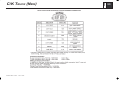
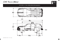
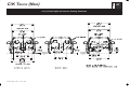
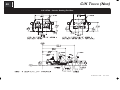
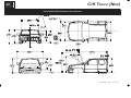
1
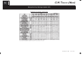
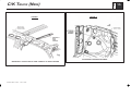
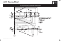
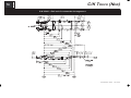
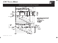
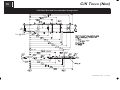
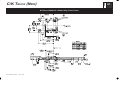
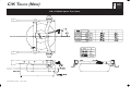
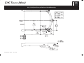
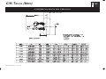
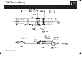
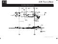
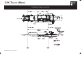
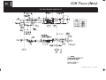
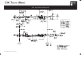
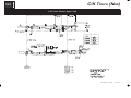
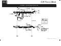
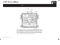
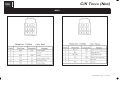
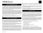
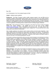
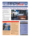
PAGE
C/K TRUCK (NEW)
BODY BUILDERS INSTRUCTIONS
The Incomplete Vehicle Document (IVD) is supplied with each incomplete vehicle,
and provides information that should be used by intermediate and final stage
manufacturers in determining conformity to applicable Federal Motor Vehicle Safety
Standards (FMVSS). The IVD also includes information which must be followed in
order to ensure that Environmental Protection Agency (EPA) and California emissions
certification requirements and NHTSA Fuel Regulations are met.
This Body Builders Book contains information that may be used in addition to the IVD
for any manufacturer making alterations to a complete/incomplete vehicle. No alteration should be made to the incomplete vehicle which either directly or indirectly results in any component, assembly or system being in nonconformance with any applicable Federal Motor Vehicle Safety Standard or Emission Regulation. Intermediate
and final stage manufacturers should be familiar with all Federal Motor Vehicle Safety
Standards and Emission Regulations and aware of their specific responsibilities as
manufacturers.
For further assistance contact Upfitter Integration at: 1 (800) 875-4742
1
When welding components to the frame assembly, remove the wax coating in the area
of the weld in order to obtain secure welds. After completion of the weld, a compatible
corrosion protection should be applied to the affected weld areas.
All labels on the vehicle (any message applied to the vehicle or vehicle component
that informs, instructs, or warns) must appear on the completed vehicle so the user
can read them easily and without obstruction.
Those installing aftermarket systems should provide information as to where and how
to obtain service and replacement parts.
When installing a Power Take-Off (PTO) with hydraulic lines, the following care should
be exercised:
Route and secure all hydraulic lines so that they are not in close proximity to
any parts of the exhaust system. Keep all fittings and connections away from
the exhaust system. Make sure connections and fittings cannot leak on the
exhaust system.
Exhaust system heat can damage and degrade hydraulic lines and
components. Oils and hydraulic fluid coming in contact with a hot exhaust
system could result in a fire.
Section 0 – General Instructions
Section 1 – Body
Check for proper clearance between body members and chassis components which
may in any way affect the reliability and performance of the vehicle by developing
abrasion and wear points from moving parts or degradation from extreme environment or thermal exposure or may increase interior noise.
Accessory items such as refrigerator, hot water heater, furnace, etc., which operate
on liquid propane gas should be located and protected to prevent exposure to any
flame.
Check headlamp aim and all vehicle illumination systems for proper operation when
the vehicle has been completed. Re-aim headlamps when necessary. Check for
proper operation of windshield washer, wipers and defroster system.
GM has established automotive refinishing standards for itsef as well as its aftermarket retailers. Each division require the dealer or retailer to use only materials and
methods that meet GM standard GM 4901M when repairing, replacing or refinishing
vehicles
Extreme care must be taken when working on vehicles equipped with Engine Control
Module (ECM), Powertrain Control Module (PCM), Transmission Control Module
(TCM), Vehicle Control Module (VCM) or any electronic unit associated with an inflatable restraint system. (See Owner’s Manual).
Each year, all new paint systems will be tested and evaluated. New or improved products will also be tested. The paint systems that pas this annual testing process will
be published in this booklet, updated annually
If arc-welding is employed on the chassis, precautions must be taken to protect all
vehicle components, especially brake and fuel lines, fuel tank assembly, electrical wiring and ECM/PCM/TCM or VCM. To avoid electronic component damage, disconnect
battery (batteries); disconnect the negative cable first, followed by the positive. To
reconnect cables; connect the positive first, then the negative.
CK New Rev. 12/98
Rev. 11/99
If GM 4901M booklets are needed, call 1–800–269–5100
Body structures, interior and accessory arrangements must be designed into the vehicle to provide for proper load distribution on both axles and not to exceed any gross
axle weight ratings. Lateral load equalization must also be maintained. The resultant
Center of Gravity of the unladen vehicle must be within the limits tabulated in the
FMVSS 105 section of the Incomplete Vehicle Document.
PAGE
2
Body insulation provided by General Motors should not be removed. This includes
any thermal or underbody heat shields. This insulation is provided to protect the vehicle body and occupants from excessive heat and/or provide noise attenuation. Any
replacement material internal to the occupant compartment must be certified for
FMVSS 302 Flammability of Interior Materials. Areas of specific concern, but not limited to are:
D Underbody exhaust, muffler and tailpipe shields and insulators.
D Rear load floor interior insulation.
D Front floor interior insulation.
D Dash mat insulation.
D Engine cowl insulation - interior and exterior.
D Engine cover insulation.
D Hood Insulation
C/K TRUCK (NEW)
lines. This allows a one time only connection to the O.E.M. charged A/C system
without having to discharge, evacuate and recharge for the connection of a rear A/C
system.
A modification to the A/C system which causes the A/C plumbing lines to increase in
length (such as the addition of a rear after-market evaporator and blower assembly)
will necessitate the following changes:
D Lubrication – PAG refrigerant oil must be added to rear system to provide
lubrication for compressor. Refer to Service Manual for specifications.
D Refrigerant – Add R-134A refrigerant to system based on sizing of new tubes,
hoses and evaporator. Contact your A/C supplier for recommended
charge.Label – Revise/modify GM charge label (located on top of front
evaporator or A/C bottle) from factory recommended charge for a front system
only to body builder’s new recommended dual system per SAE J639. This is
important for servicing the A/C system so that the technician knows the correct
amount to add to the modified system.
Conversions
A minimum of 10_ departure angle should be maintained if frame and/or body is extended.
Selected trim components above the belt line have energy absorbing foam added
behind the trim (headliners, A, B & C garnish moldings). To comply with MVSS 201
any modification could affect compliance.
If body builder installs seating other than that supplied with vehicle, it is the body
builder’s responsibility to ensure that the seating and restraint systems comply with
FMVSS requirements. The restraint systems supplied with the vehicle were designed
to accommodate the seating reference points and seat travel of the original
equipment seats only.
Air Conditioning
Section 2 – Frame
Hole drilling, welding, modifications, or alterations to the frame assembly are the responsibility of persons performing these operations. These same individuals assume
complete responsibility for frame assembly reliability, performance after alterations
and compliance to applicable FMVSS requirements.
The following procedures and specific precautionary instructions are recommended
for proper installation of special bodies and/or equipment on GM frames. Failure to
follow these recommendations could result in serious damage to the basic vehicle.
Flanges
Do not drill holes in frame flanges.
For additional information refer to Engine - Section 6.
Holes
NOTE: Air conditioning systems using R-134A refrigerant are equipped with metric fittings
to prevent interchange with R-12 refrigerant components. Do not interchange
R-134A components, refrigerant oil or service equipment with R-12 components,
refrigerant oil or service equipment.
Holes to mount brackets, supports, and out-riggers must be drilled in the vertical side
rail web with the following restrictions:
Rear Air Conditioning
This unit may be equipped with A/C quick-connect fittings (Option YF7) on the liquid
tube (high pressure) and the suction (low pressure) return tube. These fittings are
designed to accept matching Aeroquip connecting fittings attached to pre-charged
D Material between edge of hole and inside of upper or lower flange must not be
less than 37 mm (1.50 in.) for HSLA (40,000 PSI yield).
D The minimum edge distance between any two (2) holes must be larger than
twice the diameter of the larger hole.
D No holes should exceed 20 mm (0.75 in.) in diameter.
CK New Rev. 12/98
Rev. 11/99
PAGE
C/K TRUCK (NEW)
D All holes should be drilled in the frame using appropriate drilling practice and
safety precautions.
No additional holes or notching of either top or bottom frame flanges is allowed.
Section 3 – Front Suspension
Welding
CAUTION:
3
Fuel tank and fuel lines must be drained and all vapors purged to ensure
non-combustible mixture before any welding, brazing or soldering.
When welding high strength low allow (HSLA 40,000 PSI yield strength) side rails or
crossmembers and brackets (32,000 or 36,000 PSI yield strength), emphasis is
placed upon weld application techniques to avoid stress risers that may adversely affect frame operating stresses.
When welding is performed anywhere on the vehicle, precautionary measures should
be taken to prevent damage to electrical system wiring or components. Prior to any
welding, parts or components which could be damaged by excessive temperatures
must be removed or adequately shielded; the battery cables should be disconnected
at the battery. Also prior to welding, the area to be welded and surrounding area must
be cleaned of all frame protective coating. After welding, when parts are cool, carefully inspect wiring and electrical components for shorts or other damage which could
draw excessive currents and possibly cause an electrical system short when the battery is reconnected. Apply protective coating to areas where coating was removed.
Alterations
If the wheelbase is modified the alterer must take responsibility for compliance with
affected FMVSS and for warranty on items such as driveshafts, universal joints,
center bearings and rear transmission tailshaft, transfer case and transmission case
fractures, output shaft bushings, bearings, brakes, fuel systems and any other related
component failures. Additionally, the customer must be alerted in the modifier’s
owners manual that parts for the reworked area are not available through the General
Motors service parts system.
Shear Plate Attachments
Attachments of shear plates should be accomplished by using existing manufacturing
holes already available in the frame side rails. Manufacturing holes, normally 25 mm
in diameter, are consistently placed along the frame side member in the center of the
web on each frame.
When additional holes are required for shear plate attachment, they should be no larger than 19 mm (0.75 in.) in diameter. Holes are to be drilled no closer than 63.5 mm
(2.5 in.) apart. For holes drilled forward of the rear axle, centers are to be no closer
than 63.5 mm (2.5 in.) from the top or bottom flanges and no closer than 89 mm (3.5
in.) from any suspension attachments. For frame holes drilled rearward of the rear
axle, hole centers are to be no closer than 51 mm (2.0 in.) from the top or bottom flange
and no closer than 89 mm (3.5 in.) from suspension attachments.
CK New Rev. 12/98
Rev. 11/99
Since there is a large variation in completed vehicle front weight due to differences
in body weight and equipment, the front suspension alignment must be checked and
reset if necessary after the vehicle is completed. Caster and camber should be set
with reference to the “A” dimensions.
See Truck Service Manual for complete alignment procedure, specifications and
measurement of the “A” dimension under “Diagnosis and Front Alignment” section.
C/K Models are designed such that camber and caster do not need adjustment unless
severe road impact or accident deformation occurs. Toe should be reset after the vehicle is completed and while at normal operating load with trim height as specified (KModel).
Section 4 – Rear Suspension
Clearance to body should be provided for the suspension, axle, driveshaft and tires
under the following conditions: (1) Axle in full jounce against the metal-to-metal stop,
(2) Axle at 4.5_ roll with one side of axle in full jounce at the metal to metal stop and
(3) Axle at design position. Allowance for the tire chain clearance shown on a maximum grown tire must allow for 42.2 mm (1.66 in.) clearance to the sides of the tire
and 63.5 mm (2.5 in.) to the top of the tire. Be sure sufficient clearance is provided
for suspension, axle and tire and wheel in full vertical travel (up and down).
NOTE: Notification to the consumer may be required in certain states if tire chains cannot
be used.
Pipes, wiring, conduits and any other related components must not be placed where
they cross the path of motion of the rear axle, driveshaft, axle brake pipes, hoses,
spring or tires. Such crossing could result in rupture, wear-through, or separation due
to normal axle motion.
See chassis data information for additional clearances and for assistance in calculating trim heights.
Section 5 – Brakes
See Truck Service Manual for brake specifications.
PAGE
4
C/K TRUCK (NEW)
Due to the critical nature of brake systems, anyone making modifications or alterations must assume complete responsibility for system reliability, performance and
certification to FMVSS 105 or FMVSS 121.
It is mandatory that no change be made to the brake main cylinder location, brake pedal push rod length or pedal position. Ensure that hydraulic brake system is free of
air and hydraulic leaks. Bleed brakes if required, following procedures as outlined
in truck chassis service manual. Ensure that vacuum booster system or hydroboost
system is functional and free of leaks.
Check master cylinder fluid level and fill as necessary. (Refer to Owner’s Manual)
Check power steering fluid level for models equipped with hydroboost brake. (Refer
to Owner’s Manual)
Added floor covering or carpeting must not restrict service or parking brake pedal travel from released position to full pedal travel.
No body part or chassis-mounted component may be located within 2.0 in. of brake
hose routing in all wheel and axle positions. All exhaust system components must
also have a minimum of 2.0 in. clearance to brake hoses in closest positions. (Be sure
to account for brake hose travel with suspension).
Body builder is to verify that the brake warning switch is operative. The brake warning
switch on models equipped with vacuum-hydraulic brakes is located on the master
cylinder. This includes both the brake system fluid level and parking brake actuator
switch.
Section 6 – Engine
Due to the critical nature of the accelerator system, anyone making modifications or
alterations assumes complete responsibility for system reliability, performance and
compliance to FMVSS 124. Caution must be exercised so that the accelerator cable
is properly routed. Specifications are as follows:
Route cable to maximize all bend radii. In no case should bend radii be less
than 3 in. (76 mm).
Minimum distance from exhaust manifold to be 6.0 in. (150 mm), unless a heat
shield is provided.
Do not use accelerator cable or clips to route wires, harnesses or other cables.
Cable sheath must be clipped so as not to pinch inner cable. Cable must not
be loose in clip allowing sheath to move when accelerator pedal is applied and
released.
Cable must not be subjected to kinking or routing across any sharp edges.
Cable routing must be perpendicular to the surface of the front-of-dash at the
dash fitting. No objects or routings should force cable to have a bend at the
dash fitting. Flexible components (hoses, wires, conduits, etc. ) must not be
routed within 2.0 in. (50 mm) of moving parts or accelerator linkage unless
routing is positively controlled.
Caution must be taken so that the accelerator pedal remains properly located.
Guidelines for accelerator pedal locations are as follows:
1) Ensure that the accelerator can freely operate from idle to wide-open throttle
position and return. Make sure that the pedal will not hang up on any nearby
items such as carpets, floor, screws, wiring harnesses, etc. Engine cover
should have at least one inch (25 mm) clearance to side of accelerator pedal
with the carpet mat installed.
2) Accelerator to brake pedal relationship has been designed to provide minimum driver movement and should not be altered in any way.
For additional information refer to Body - Section 1.
Air conditioning and auxiliary belt-driven equipment installation recommendations:
No alterations or additions to the accessory drive belt system will be warranted on serpentine belt systems.
The serpentine belt type of drive is designed as a total system, incorporating a single
poly-V belt and an automatic tensioner. In this type of system, degrees of pulley wrap,
belt tension, and pulley alignment are very critical factors. Modification is not recommended.
In some single belt serpentine systems, belt tension is determined by the automatic
tensioner and its position relative to the belt. No adjustment required.
Gasoline engine induction and/or ignition system is certified in compliance with the
Federal Vehicle Emission Standards. Any alterations to the systems or components
could void compliance and render the vehicle illegal. System includes:
Fuel system – throttle body injector (TBI) or central port injector (CPI) and
associated tubes, hoses and pipes, air cleaner outside air hose and spacer
heat stove and heat stove pipe, fuel pump and inlet manifold, fuel vapor
canister.
Exhaust system.
Ignition system distributor and initial spark timing setting, spark plugs, spark
plug wires.
CK New Rev. 12/98
Rev. 11/99
PAGE
C/K TRUCK (NEW)
D Crankcase ventilation system.
5
operating temperatures. The lubricant is installed in all NV4500 transmissions
at the factory.
Diesel engine induction and injector pump system is certified to be in compliance with
the Federal Vehicle Emission Standards and/or Noise Standards. Any alterations to
the system or components could void compliance and render the vehicle illegal. System includes:
D In instances where it is necessary to drain and refill or add fluid to the
transmission, such as when installing PTO, DO NOT substitute any other
lubricant. Installation of other lubricants may result in internal transmission
damage.
D Fuel system – Injection pump, injector lines and injectors, fuel return hoses and
pipes, air cleaner, outside air hose, fuel pump, fuel filter, fuel heater assembly
and intake manifold.
D Castrol Syntroq GL4 is the only synthetic lubricant currently approved for use
in the NV4500. This product can be secured through your local GM dealer
under GM part number 12346190 per quart.
D Exhaust system.
D Transmission lubricant capacity is 8.5 pints.
D Crankcase pressure regulation system.
D Charge air cooler system.
Models equipped with manual transmission use a hydraulic clutch actuator. Check
fluid level as outlined in the vehicle owners manual.
D External engine components such as air cleaner, crankcase pressure
regulator valve, alternator, injection pipes, fuel return hoses from injectors,
exhaust manifolds, oil fill pipe, etc. must be provided with sufficient clearance
for engine roll and torque.
It is mandatory that no change be made to the clutch master cylinder location, clutch
master or slave cylinder push rod length, or pedal position.
D When a vehicle is equipped with a electronic fuel injection (EFI) engine, it has
an engine control module ECM/PCM/TCM or VCM. This ECM/PCM/TCM or
VCM must be maintained at a temperature below 185_F at all times. This is
most essential if the vehicle is put through a paint baking process. The
ECM/PCM/TCM or VCM will become inoperative if its temperature exceeds
185_F. Therefore, it is recommended that temporary insulation be placed
around the ECM/PCM/TCM or VCM during the time the vehicle is in a paint oven
or undergoing another high temperature process.
Section 7 – Transmission
Light duty models equipped with manual transmission have a clutch-operated start
safety switch. Starter should operate whenever the ignition is turned to start and the
clutch is fully depressed. Readjust if necessary as outlined in the Truck Service Manual.
Models equipped with automatic transmissions have a steering column mounted neutral/park start safety mechanical lockout feature, which interfaces with the steering
column ignition switch. Starter should operate only when gear shift lever is in neutral
or park position. Readjust the shift linkage if necessary as outlined in the Truck Service Manual.
Power Take-Off (PTO) systems refer to General - Section 0.
D The NV4500 manual 5-speed heavy-duty overdrive transmission (RPO MW3)
requires the use of special synthetic lubricant to reduce transmission internal
CK New Rev. 12/98
Rev. 11/99
Section 8 – Fuel and Exhaust
Fuel Systems
The fuel evaporative emission control equipment is certified to be in compliance with
the Federal and California Vehicle Emission Standards. The fuel tank is molded from
multi-layer plastic and should not be repaired or altered. Metal fuel lines have a surface coating to reduce corrosion on inside and outside surfaces to comply with useful
life requirements. All fuel hoses, including plastic lines, are made of a low permeation
multi–layer material to comply with enhanced evaporative emission requirements.
Any alterations to systems or components including materials, hose lengths and their
location, except as described in the fuel fill system modifications section, could void
compliance. The system includes:
D Fuel tank, fuel level sender, fuel fill and vent hoses and pipes, emission
canisters, fuel feed, fuel return and vapor lines, purge control solenoids, fuel
fill cap, canister vent solenoid.
For these reasons,
NO ALTERATION OF THE FUEL SYSTEM IS RECOMMENDED
Fuel Fill
It is recommended that when mounting the fuel filler pipe assembly and vent hose that
a minimum of 3.0 in. clearance be provided to any body component to prevent contact
PAGE
6
C/K TRUCK (NEW)
between hoses and/or mating parts and that retention be provided to ensure routing
and prevent failure due to wear and fatigue. Both the fill and vent hoses must be
routed (and supported, if needed) such that there are no sags or kinks. As viewed
from the filler neck, pipes and hoses must have a downward slope toward the tank.
There should be a minimum of 4° of downward slope in the fill and vent pipe at any
location. No fuel traps are allowed. Alterations of fuel line routings could affect the
ability of the completed vehicle and are, therefore, not desirable. The complete fuel
system must comply with FMVSS 301.If additional new hose is required when
installing fuel tank filler neck, this hose must be suitable for use with unleaded fuels
or diesel fuel respectively and must allow the vehicle to meet enhanced evaporative
emissions requirements.
Body attachment brackets and u-bolts must be located such that there is adequate
clearance to all fuel system components, such as the fuel lines and the fuel level
sending unit, under all operating conditions. Fuel Tank
Fuel Lines
The use of auxiliary fuel tanks is not recommended. If an auxiliary fuel tank is
added, the alterer must take responsibility for compliance with affected motor vehicle
safety standards. Also, if an auxiliary fuel tank is added to a gasoline-powered
vehicle, the fuel must be drawn through a pipe at the top of the tank (balance line
between tanks is not permitted).
Fuel line routing precautions:
5 in. minimum clearance to exhaust system is required or a metal shield must
be provided.
Fuel lines should be clipped to chassis to prevent chafing. Metal clips must
have rubber or plastic liners.
Use corrosion resistant steel tubing with short sections of approved hose to
connect components. Hose-to-tube connections should be clamped for diesel
systems. Steel tube ends should be beaded for hose retention. Fuel supply
is pressurized by an in-tank pump for MPFI and SCPI systems. Coupled hose
or nylon quick-connects must be used. Clamped hose is not acceptable for
MPFI and SCPI systems.
All engines require a fuel return system which returns excess fuel from the injection
pump and injector nozzles back to fuel tanks. Care should be taken that these lines
are not blocked nor their hoses pinched. The engine may run poorly or stall if these
lines are restricted or blocked.
All gasoline engine vehicles are equipped with fuel evaporative emission control
equipment which is certified to be in compliance with the Federal or applicable
California vehicle emission standards. Alterations to fuel tank and metering unit,
lines, canister or canisters, canister filters, canister purge control valves, relay
switches, tank auxiliary vent valve, engine speed controller, or other devices/systems
are therefore not allowable since vehicle adherence to C.A.R.B. and Federal
regulations may be affected.
Diesel powered vehicles incorporate water drain provisions in the fuel system. These
valves are only to be opened when siphoning water and contaminants from the fuel
system.
Fuel Tank
For vehicles with full frames, the tank must have a minimum clearance of 2 in. top,
front, rear and sides to body and other supports.
Tank may be pressurized to 1.25 PSI maximum to check for final line leakage or for
forcing fuel through the system. Pressures greater than this amount may be
detrimental and affect tank durability.
Gasoline fueled vehicles are equipped with a fuel pump return line. If an auxiliary tank
is added, the tank selector valve must include a return port which returns fuel to the
tank from which the fuel is being drawn.
In gasoline engines the fuel pump is located in the fuel tank. The battery must be
disconnected before starting any work on the fuel system.
Gaseous Fuel Conversions
All truck gasoline engines may be converted to use liquified petroleum gas (LPG) or
natural gas (NG); GM only approves the conversion of vehicles with option KL5 in
combination with engine L31 (5.7L). However, some conversions may cause harmful
effects to the engine. Such fuel systems may require assurances from alternate fuel
system manufacturers and/or installers that the equipment will not cause damage to
the engine or the exhaust system.
In the use of dual fuel systems, the vehicle operator should strictly adhere to the
manufacturer’s procedures for switching from gasoline to gaseous fuel operation.
Improper switching procedures may result in overheating and damage to the exhaust
system and the vehicle. The gaseous fuel tank should not be mounted in an enclosed
area of the vehicle, such as the passenger compartment, truck, etc., and the system
should be vented to the outside of the vehicle. In addition, vehicles converted to
gaseous fuels should not be stored in enclosed places such as garages. Further,
General Motors cautions purchasers that the design, location and installation of any
type of fuel storage system involves significant technical and engineering
CK New Rev. 12/98
Rev. 11/99
PAGE
C/K TRUCK (NEW)
considerations and that these statements on gaseous fuel conversions should not be
interpreted to be an approval by General Motors of any modification to the original
equipment fuel system. Conversions to gaseous fuel should be made in conformance
with applicable Federal and State regulations. Removal of emission-control
components, or the addition of gaseous fuel systems which could damage or reduce
the longevity of those components and could also cause the mechanical and emission
performance warranty to be voided.
Exhaust System
Exhaust system materials are selected and tested to withstand the operating
environment of the vehicle. Do not modify the exhaust system in any way. The
tail pipes are made of 409 stainless steel.
Heat shields are mounted to the underbody and/or exhaust system components
(catalytic converter and muffler). Shields for the propshaft hanger bearings are also
provided in some vehicles.
Section 9 – Steering
Particular care should be taken to prevent the possibility of exhaust fumes and carbon
monoxide exposure to vehicle occupants in units completed by body builders. Holes
and openings through the floor and all other parts of the body must be permanently
and adequately sealed by the body builder to avoid exhaust intrusion into any
occupant area. If it is necessary to change the exhaust outlet location, the exhaust
discharge must be unobstructed and directed away from occupant areas. Alteration
of the exhaust outlet or its position may increase exhaust noise and render the vehicle
illegal in those areas with pass-by noise regulations. All vehicles >10,000 lbs. GVWR
come under Federal noise regulations, vehicles <10,000 lbs. GVWR are regulated
by various state and local regulations of the Environmental Protection Agency; see
those regulations for rules, test procedure and noise levels permitted.
Tail pipe outlet location must be tested statically and with the vehicle in motion to ensure that exhaust gases do not penetrate side or rear windows or under body seams
and holes. Auxiliary power plants should also be tested under the same conditions.
Tail pipe exit ahead of rear wheels is not recommended.
Check for leaks in exhaust systems and repair as required.
Exhaust temperatures can exceed 1600_F under extreme operating conditions, with
pipe surface temperatures slightly less than this. Extreme care must be used when
placing body components in the proximity of the exhaust system so as not to exceed
the rated temperature limits of the components. Due to variants in underbody configurations of the vehicles, we are not in a position to make recommendations on how to
insulate or design components in the proximity of the exhaust system.
Each manufacturer must make temperature checks of critical areas of his vehicle and
adjust his design accordingly, or provide shielding to ensure safe operation of his body
components.
The same can be said for the engine compartment. Obviously there will be additional
heat radiated from the engine. How much is retained in the area will depend on how
well this area is ventilated in your individual designs. Here again, temperature checks
of interior areas surrounding the engine should be made to determine if your
insulation is adequate. This is the same engineering practice we have followed on
our complete vehicles incorporating these exhaust systems.
CK New Rev. 12/98
7
Rev. 11/99
Check power steering fluid level and system operations. (Refer to Owner’s Manual)
Steering wheel and horn pad must not be altered or replaced.
The steering column mast jacket not to be altered.
Section 10 – Tires
Check wheel lug nuts for proper torque; specifications are provided in the Owner’s
Manual.
Substitution of tires of greater capacity than those offered as original equipment by
vehicle manufacturer is not approved for use on original equipment wheels. Any
usage of higher capacity tires must be accompanied by higher capacity wheels.
However, the wheel offset (the distance from centerline of rim to wheel mounting face)
must be the same as the replaced original equipment wheel to ensure proper wheel
bearing loading and clearance of tires to body and chassis components. Increasing
tire and wheel capacity does not necessarily increase vehicle GVW ratings.
Any substitution of tires may affect Speedometer/Odometer accuracy.
It is recommended that tire chain clearance guideline, J683 from the Society of Automotive Engineers be adhered to in designing rear wheelhouse clearance.
Check tires and inflate to recommended tire pressure according to the tire pressure
information provided in Owner’s Manual and tire inflation label provided with vehicle.
PAGE
8
C/K TRUCK (NEW)
Section 12 – Electrical Battery and Battery Cables
The vehicle battery should be located and positioned to make use of the existing
battery cables. If the battery requires relocation and longer cables are required, a
proportionately larger gauge wire must be used. If in relocating the battery the
negative ground cable is attached to frame rail, a cable of similar gauge be provided
between the frame rail and the engine. This is required due to the heavy electrical
loads imposed by the starting circuit. To ensure proper operation of the battery cables
the following chart on length, gauge and materials must be strictly adhered to:
Combined length of positive and negative
Cable Gauge
Cable in Inches (Copper)
4
66
2
107
0
170
The All New C/K is equipped with a Remote Positive (+) Jump Starting terminal which
is located behind a red plastic cover near the engine accessory drive bracket. This
terminal is intended for jump starting only and should NOT be used by upfitters to
obtain battery power. Three fused studs, howerver, are available on the Underhood
Electrical Center and, if available, may be used by upfitters to obtain battery power.
If the battery is remotely mounted (other than in the engine compartment) the ‘sense’
circuit in the generator regulator shall be used. The sense circuit consists of a 7.76
OHM 1/4 watt resistor connected in series between the ‘S’ terminal of the generator
and the B+ terminal of the battery.
Auxiliary Battery (Gasoline Engines Only)
If an auxiliary battery is to be retro-fitted, the electrical schematic for option TP2 is
recommended as a guide. This will result in the auxiliary battery being connected to
the vehicle load and charging circuit when the ignition switch is ‘on’ (fuse block
terminal “Acc.Ign.Fused”). When the ignition switch is turned off, the interlocking
relay is disengaged and the auxiliary battery is disconnected from the vehicle circuit.
Modifications/add-on wiring must be carefully reviewed to ensure compatibility with
the base vehicle wiring by reviewing system schematics, wire routing paths, harness
connections, etc. Due to the wide range of modifications that may be required for
vocational needs, it is not feasible for the O.E.M. to take into account all potential
revisions. For this reason, any person modifying existing vehicle wiring must assume
responsibility that the revisions have not degraded the electrical system
performance. Any add-on wiring must be properly fused and routed to prevent cut,
pinch, and chafe problems, as well as avoid exposure to excessive heat. Care must
be exercised that existing vehicle interfaces do not have their current load capabilities
exceeded, and that the respective control devices are not overloaded. Added wire
size should be at least as large as the the wire to which it is attaching in order for fuse
protection to be maintained.
A Packard electric wiring repair kit is available through Kent–Moore (GM P/N
12085264, Kent–Moore P/N J38125-4). This kit contains instructions, tools and
components for making repairs to wiring harness components. This kit would also
greatly assist in accomplishing necessary add-on wiring such as body marker lamps,
so that system reliability/durability is maintained.
Electrical wiring components can be obtained through your authorized GM dealer.
Many Packard Electric components are also available through Pioneer Standard
Company (1-800-PACKARD). Pioneer may also be able to assist in making necessary
wiring additions by providing custom wiring stubs or jumpers to your specifications.
Section 13 – Cooling
To provide satisfactory engine cooling, the following conditions must be met:
1. Do not locate any large objects in front of the radiator core or grille such as batteries,
spare tires, lights/sirens, etc. They restrict air flow into the radiator core and influence fan blade stress.
2. Grille opening, size configuration and the external baffles provided should not be
altered in any manner. Any reduction in cooling ability may adversely affect
engine/transmission performance.
3. Fan clutches not conforming to the original equipment specifications may not
operate correctly and may stay “on” continuously, never come on, or cycle on and
off excessively. This will result in a reduction of fuel economy, engine overheat at
times, and annoying cycling respectively.
4. Heavy duty cooling equipment is required when snow plows, winches, etc. are
installed.
5. If a heater unit is not installed in the vehicle or a heater shut-off valve is required,
a line connecting the heater connection on the engine to the heater connection on
the engine must be installed. When a shut-off valve is required in heating system,
it must be teed into the system in such a manner as to maintain continuous flow
between engine heater connection - radiator heater connection at all times.
Do not install any internal flow restrictors.
Heater hose:
3-way or 4-way valves must be used to provide constant water flow through the
intake manifold pad area used to mount the TBI unit (L35 only).
NOTE: TBI unit does not have internal coolant passages.
CK New Rev. 12/98
Rev. 11/99
PAGE
C/K TRUCK (NEW)
9
Model Symbol Chart
Series
C/K 157
C/K 159
2 Door Pickup
Fleetside/
Wideside
2 Door Pickup
Sportside
03 + E63
(6.5’ Box)
03 + E62
(6.5’ Box)
Nominal Ton
Rating
Wheelbase (in.)
Cab to Axle (in.)
C/K 6100
1/2
119.0
42
C 6200
K 6400
1/2
143.5
42
C/K 6400
1/2
133.0
56
53 + E63
(8.0’ Box)
C 6200
K 6400
1/2
157.5
56
53 + E63
(6.5’ Box)
C/K 7200
K 8600
3/4
143.5
42
C 7200
C/K 8600
3/4
133.0
56
C 7200 & L56
C/K 8600
3/4
157.5
56
03 + E63
(8.0’ Box)
03 + E63
(8.0’ Box)
53 + E63
(8.0’ Box)
Series
4 Door Utility
C/K 157
06
3 Door
Extended Cab
Rear Seat
Access Panel
Sportside
GVW (lbs.)
53 + E63
(6.5’ Box)
C/K 257
C/K 259
3 Door Extended
Cab Rear Seat
Acces Panel
Fleetside/
Wideside
Suburban
53 + E62
(6.5’ Box)
GVW (lbs.)
Nominal Ton Rating
Wheelbase (in.)
C 6500/6800
K 6800/6900
1/2
116 0
116.0
1/2
130 0
130.0
3/4
130 0
130.0
C/K 159
06
C 6800
K 7200
C/K 259
06
C/K 8600
CK New Rev. 12/98
Rev. 11/99
PAGE
10
C/K TRUCK (NEW)
C/K (15/25)703 General Arrangement
CK New Rev. 12/98
Rev. 11/99
PAGE
C/K TRUCK (NEW)
C/K 15706 General Arrangement
CK New Rev. 12/98 . . Rev. 11/99
11
PAGE
12
C/K TRUCK (NEW)
C/K (15/25) 906 General Arrangement
CK New Rev. 12/98
Rev. 11/99
PAGE
C/K TRUCK (NEW)
13
SNOW PLOW INSTALLATION
The chart on the following page shows GMTG approved models available with snow
plow prep package–option VYU.
General Motors recommends that when a snowplow is mounted on a vehicle, only one
passenger should accompany the driver. More than one passenger may exceed
Front Gross Axle Weight Ratings.
Prior to installing a front mounted snowplow, the following process should be followed
and necessary information obtained.
D Establish vehicle curb weight
D Establish chassis manufacturers front and rear axle weight ratings
D Chevrolet and GMC truck dealers can provide availability, specifications
weights Gross Vehicle Weight Ratings (GVWR) and Front and Rear Gross Axle
Ratings (GAWRF/GAWRR). For vehicles already built, this information can be
found on the certification label installed on drivers door/door frame or provided
on cover of incomplete vehicle document.
The following information should be obtained and provided by the manufacturers of
snowplows and salt spreaders:
D Specifications, Weights and center of gravity data
D Vehicle installation guidelines and instructions
D Calculation of weight distribution for the front and rear axles
The loaded vehicle with driver, passengers, aftermarket accessories, snowplows,
spreader, and cargo must not exceed Gross Vehicle Weight Ratings (GVWR), Front
and Rear Gross Axle Weight Ratings.
Ballast Compensating Weight
The use of ballast weight may be required to prevent exceeding the Gross Axle Weight
Rating of the front axle. Ballast should be securely attached in the pickup box or behind the rear axle of vehicle.
Electrical Provisions
Emergency Roof Mounted Lamp. This provision includes a dash mounted switch
a relay and wiring which is routed up along the Left Hand B pillar and terminates at
the roof as coiled blunt cut wires (see Figure 1). There are two blunt cut wires, 12
gauge (3.0mm@) wires, one is Brown (roof mounted lamp power), it is controlled by
the dash mounted switch through the relay, the other is Black (ground). The Brown
power wire is protected by the 30 Amp SEO 2 fuse which is located in the Underhood
Electrical Center.
Forward Lamp Harness In Line Connector. The forward lamp wiring harness will
have a set of mating eight cavity connectors on both the left and right hand side of
the vehicle (see figures 3 & 4). The upfitter will be able to disconnect the in line
connectors which will allow interfacing with the forward lamp circuits (Front Parklamp,
Turn Signal and DRL). The headlamp circuits must be accessed from the headlamp
connectors. Circuit function charts of these connectors are on page 17. Connrctor
A parts list of these connectors is provided on page 18.
130 Amp Generator. The AD244 130 Amp generator will be equipped on all VYU
pickup trucks except those having the Vortec 4300 V6 (L35) engine. The AD244 generator is an up grade from the AD230 105 generator which comes as standard equipment
Back–up Lamp Power Feed. Although this feature is standard on the All New C/K
pickup trucks, it should be pointed out that a backup lamp power feed is provided at
the rear of the vehicle through the trailer wiring harness. This circuit is protected by
the 10 Amp TRLR B/U fuse which is located in the Underhood Electrical Center. On
vehicles with Light Duty Trailer Wiring which comes standard, this circuit can be
accessed through the Light Green trailer wire. This wire is blunt cut and located at
the rear of the vehicle along with other trailer tow circuits. On vehicles with Heavy
Duty Trailer Wiring option, this circuit is located in pin A of the trailer in line connector
at the rear of the vehicle.
Accessory Harness Grommet. Trucks will come equipped with a predrilled 42mm
pass through hole located on the dash panel on the left hand side of the vehicle. The
hole will be sealed with a grommet (see Figure 2) which can be used by the upfitter
for pass–through wiring. To use the grommet (part# 15336702), the upfitter slices
off the tape tab end (in engine compartment) of the grommet and then spreads it open
to pass wiring through.
CK New Rev. 12/98 . . Rev. 11/99
PAGE
14
C/K TRUCK (NEW)
Snowplow Prep Package–Option VYU
Snowplow Prep Package – Option VYU
CK New Rev. 12/98
Rev. 11/99
PAGE
C/K TRUCK (NEW)
FIGURE 1
FIGURE 2
ACCESSORY HARNESS GROMMET
EMERGENCY VEHICLE ROOF LAMP HARNESS TO ROOF HEADER
CK New Rev. 12/98 . . Rev. 11/99
15
PAGE
16
C/K TRUCK (NEW)
FIGURE 3
FIGURE 4
LH FRONT OF VEHICLE
RH FRONT OF VEHICLE
CK New Rev. 12/98
Rev. 11/99
PAGE
C/K TRUCK (NEW)
17
FRONT EXTERIOR LAMP CONNECTOR CIRCUIT FUNCTION CHARTS
FRONT EXTERIOR LAMP ELECTRICAL CONNECTOR PART NUMBERS
Note:
Note: All fuses referenced above are located in the underhood Electrical Center
CK New Rev. 12/98 . . Rev. 11/99
Terminals and secondary locks may have to be ordered separately.
Further details regarding the connectors can be obtained from the Delphi
Products Handbook or by calling 1–800–PACKARD (1–800–722–5273)
PAGE
18
C/K TRUCK (NEW)
FORWARD LAMP HARNESS IN–LINE CONNECTORS
HEADLAMP CONNECTORS
CK New Rev. 12/98
Rev. 11/99
PAGE
C/K TRUCK (NEW)
PICKUP BOX REMOVAL PROGRAM
The following information is for vehicle alterers who intend to remove Pickup boxes from
C/K Trucks and install second unit bodies on these vehicle. This information applies only
to those vehicles which have a Gross Vehicle Weight Rating (GVWR) Of 6100 lbs. up
to and including 10,000 lbs. (Vehicles listed in Table A).
Alterations to Complete Vehicles
Persons who alter complete (certified) Pickup Trucks by removal of the Pickup box
should be aware that this type of activity would impose upon them the corresponding
responsibility for ensuring that the units as sold are in compliance with all applicable
safety and/or emissions (including noise and RFI) requirements. Specific questions
concerning compliance or certification to these requirements should be directed to
the vehicle alterer’s legal counsel or the National Highway Traffic Safety Administration, The Environmental Protection Agency, The California Air Resources Board, or
in Canada, The Ministry of Transport or The Canadian Department of Commerce.
19
The Maximum vehicle weight for a given vehicle is determined by:
A) Subtracting 300 lbs. from the highest loaded vehicle weight (see 40 CFR
86.079–2 for loaded vehicle weight definition and the table at 40 CFR
86.129–80) associated with the test weight listed in the application for the
vehicle, and
B) Adding the weight of all options that are offered by the original manufacturer
for the applicable truck line that were not included in the curb weight reported
in the application.
In the case of mutually exclusive options, only the weight of the heavier option is to
be used when computing the maximum vehicle weight.
Some original manufacturers provide their sales organizations with a “Data Book” that
lists the curb weights of complete Light Duty Trucks equipped with standard equipment (not including their weight) the original manufacturer offers. A secondary
manufacturer may use the “Data Book” Curb weight and option weight to determine
the maximum vehicle weight for a given vehicle by adding the weight of every option
offered by the original manufacturer for the vehicle to the curb weight in the “Data
Book” curb weight only when the vehicle in question actually contains these options.
The Environment Protection Agency has provided an explanation of the policy they
will follow regarding the modification by the secondary manufacturers of complete
Light Duty Trucks prior to sale and delivery to the ultimate purchaser. This explanation
is constrained in a letter from C.N. Freed of the EPA to M.M. McBride of the Recreation
Vehicle Industry Association, dated July 13, 1979. A portion of this letter states:
Those who wish to remove the Pickup Box from a Pickup Truck for the purpose of
installing special equipment or another type of body should be further advise that a
Pickup may require modification in one of the following areas. Before a decision is
made to alter a C/K Pickup Model, please be advised of the following considerations:
“...Secondary manufactures are not manufacturers under the act when the following
conditions are met:
Vehicle:
Analyze the vehicle specifications for product content. the option content of a particular vehicle will determine which if any of the four area of modification might not be applicable to the vehicle alterations contemplated.
1. The vehicle produced by a secondary manufacturer conform in all material respects
to the design specification in the original manufacturer’s application for certification
(hereafter’ application’); and
2. The weight of the vehicle produced by a secondary manufacturer, including the
weight of fuel at nominal tank capacity, is no more than 500 lbs. above the maximum
vehicle weight.”
No frontal area restrictions will apply to secondary manufacturers who comply with
the conditions above . However, every vehicle sold to an ultimate purchaser must be
covered by emission warranty mandated by section 270(a) of the Act. Secondary
manufacturers who do not meet the above conditions will be considered manufacturers under the Act and will be required to ensured that the vehicle they produce are
covered by a certificate of conformity.
Service Parts:
The service parts and related service part number as outlined in the four areas of modification my be ordered throughout your local Chevrolet/GMC Dealer. Contact your
Dealer’s Service Parts Representative for availability and price.
Areas of Modification
1.Fuel filler neck assembly and housing
2.Tail lamp, tail lamp wiring harness and license plate bracket assembly
3.Fuel tank filler pipe ground strap.
4.Spare tire mounting.
CK New Rev. 12/98 . . Rev. 11/99
PAGE
20
C/K TRUCK (NEW)
ALLOWABLE CENTER OF GRAVITY CHARTS
CK New Rev. 12/98
Rev. 11/99
PAGE
C/K TRUCK (NEW)
Fuel Fill System Modifications For Gasoline Vehicles
Parts are provided through your Chevrolet/GMC Dealer to convert the fuel fill and vent
system to meet the packaging requirements of the particular bodies that are installed
on the chassis. See page 8 for part numbers.
Certain guidelines must be adhered to in modifying the fuel fill and vent system to ensure that the completed product meets the manufacturer’s requirements.
1. The fill and vent system must be installed such that there is adequate clearance
between the fuel fill vent system and the tires under all operating conditions.
Body attachment brackets and must also be located such that there is adequate
clearance to all fuel system components, such as the fuel lines and the fuel level
sending unit, under all operating conditions.
2. the fuel fill/vent pipe system available from the dealer includes a number of additions hose retaining beads. The pipe can be trimmed at the hose retaining beads
to adjust for the various chassis lengths and body widths. The pipes must be
trimmed only at locations where a hose retaining bead is present. A hose retaining bead must be present at each pipe to hose interface in a modified fuel fill and
vent system. Pipe ends must be free of burrs which may be detrimental to satisfactory assembly and, or function.
3. A minimum of 8.0 inches of fill hose must be maintained between the filler neck
and the fuel tank as measured in an outboard direction from the tank surface (at
the fill hose nipple) to the outlet end of the filler neck.
4. Both the fill and the vent hoses must be routed (and supported, if needed) such
that there are no sags or kinks. Excess hose length may be removed as required
provided hose does not kink. As viewed from the filler neck, pipes and hoses
must have a downward slope toward the tank. There should be a minimum of 4_
of downward slope in the fill and vent pipes at any location.
5. The fuel fill and vent system should be restrained in the upfit vehicle. This is necessary to avoid chaffing, fretting, rubbing, etc. which may cause wear to the pipes
or hoses.
6. Fuel fill hose clamps are to be tightened to 22lb–in torque.
7. Fuel vent hose clamps are to be tightened to 16lb–in torque.
8. Route the rear axle vent hose using the clips on the frame and the bracket on the
fuel filler neck assembly.
CK New Rev. 12/98 . . Rev. 11/99
21
The FMVSS Regulations and the U.S. EPA and California Exhaust and Evaporative
Emission Requirements found in the 1999 Body Builder Manual (Current C/K Pickup
Box Removal Program Section) are valid for the 1999 All New Silverado/Sierra Pickup
Box Removal Program. Please refer to the Current C/K Pickup Box Removal Program
Section of the 1999 Body Builder Manual to assure compliance.
The Parts required to replace the existing fuel fill system (ZW9) are:
– Pipe Assembly–Fuel Tank Filler
Part Number: 15008136
– Pipe Tank Filler Cap
Part Number: 15001538
PAGE
22
C/K TRUCK (NEW)
Fuel Tank Filler Neck (Gas)
CK New Rev. 12/98
Rev. 11/99
PAGE
C/K TRUCK (NEW)
FUEL FILLER PIPE ASSEMBLY TO FRAME
CHASSIS CAB (ZW9) TRUCKS
PICKUPS WITHOUT (ZW9)
CK New Rev. 12/98 . . Rev. 11/99
23
PAGE
24
C/K TRUCK (NEW)
REAR AXLE VENT HOSE (ZW9)
REAR AXLE VENT HOSE (ZW9)
CK New Rev. 12/98
Rev. 11/99
PAGE
C/K TRUCK (NEW)
25
Tail Lamp Wiring Modifications
REAR JUNCTION BLOCK
COMBINATION LAMPS ON ALL NEW C/K CHASSIS
The tail lamp wiring on the All New C/K is routed to a junction block located at the rear
of the vehicle. This junction block interfaces with the rear chassis harness and breaks
out the license lamp, left turn lamp and right turn lamp connections (see page 16 for connector face view). A schematic diagram of the Rear Junction Block and tail lamp circuits
is shown on page 17. On trucks without the Pickup Box Delete (ZW9) option, this junction
block is attached to the underside of the box and therefore must be relocated when removing the box. On trucks with ZW9, this junction block is attached to the left frame rail
(see pages 18 & 19).
The All New C/K tail lamp wiring was designed for separated function Stop and Turn
lamps, therefore, the tail lamp feeds from the rear junction block cannot be used directly
for combination stop/turn lamps. Feeds for combined stop/turn lamps are, however,
available off of the trailer tow harness. Trailer wiring is incorporated on all of the All New
C/K trucks in one of two forms, Light Duty trailer wiring or Heavy Duty Trailer Wiring. On
trucks with Light Duty trailer wiring, the trailer harness is tied back to rear cross member
(see Basic Trailer Wiring Package on page 25). On trucks with Heavy Duty trailer wiring
the trailer harness is run to the universal trailer connector at the rear of the vehicle (see
Heavy Duty Trailer Wiring Package on page 25).
The parts required to relocate the Rear Junction Block to left frame are as follows:
–Junction Block
–Junction Block Bracket
–Bolt/Screw (two required)
Part Number: 12191376
Part Number: 15034931
Part Number: 11516885
REAR TAIL LAMPS AND LICENSE PLATE LAMP
Trucks originally ordered with the ZW9 option will come equipped with separated
function (stop, turn, park, backup) tail lamps which attach to the frame rails. The
license plate lamp assembly will be attached to the left frame rail as shown on page
20. Pages 20 to 24 provide the assembly sequence for the tail lamps and license plate
lamp assemblies for trucks built with the ZW9 option.
The parts required to install the rear tail lamps and license plate lamp assembly are as
follows:
–Tail Lamp Assembly – LH
–Tail lamp Assembly – RH
–Rear License Plate Lamp Assembly
–Stud/plate Assembly (two required)
–Nut (four required)
CK New Rev. 12/98 . . Rev. 11/99
Part Number:
Part Number:
Part Number:
Part Number:
Part Number:
15029717
15029718
15154884
15008506
11516796
The Left Stop/Turn Lamp feed can be accessed from the Yellow wire (circuit 1618).
The Right Stop/Turn Lamp feed can be accessed from the Dark Green wire (circuit
1619). A schematic diagram of the above mentioned trailer feed circuits is provided on
page 26. If using these feeds, the upfitter must consider whether the truck will be used
for trailer towing. If so, the upfitter must ensure that the loads of the truck stop/turn lamps
combined with the trailer stop/turn lamps do not exceed the capacity of the circuits. Load
guidelines for this as well as splicing guidelines can be found in the Upfitter Integration
Electrical Guideline Manual.
REAR CHASSIS WIRING HARNESS AND REAR LAMP CONNECTOR FACES
A connector face diagram of the Rear Chassis Harness Connector is shown on page 27.
As was mentioned above, under the Rear Junction Block heading, the Rear Chassis
Harness interfaces with the Rear Junction Block where the rear lamp circuits are broke
out. If the upfitter prefers to interface directly with this connector, thus eliminating the
Rear Junction Block, an in–line mating connector is available and can be obtained by
ordering part number 15326788. Connector faces for the Tail Lamp Connectors and
Rear License Plate Lamp Connector are also provided and are shown on pages 28
through 30. Please note that these connectors can either be purchased from a local GM
dealer or through Packard by calling 1–800–PACKARD (722–5273).
PAGE
26
C/K TRUCK (NEW)
REAR JUNCTION BLOCK AS VIEWED FROM REAR OF VEHICLE WITH ZW9
CK New Rev. 12/98
Rev. 11/99
PAGE
C/K TRUCK (NEW)
REAR JUNCTION BLOCK ELECTRICAL DIAGRAM
LT
TURN
10A
VEH
STOP
10A
LR
PARK
10A
2115
LIGHT
GREEN
UNDER
HOOD
ELECTRICAL
CENTER
DARK
BLUE
TO LIGHT DUTY
TRAILER HARNESS
LIGHT
1324 GREEN
REAR CHASSIS
CONNECTOR
PART #15305595
A
B
C
D
A
E
B
LEFT HAND TAIL LAMP
CONNECTOR
PART#15305596
CK New Rev. 12/98 . . Rev. 11/99
RT
TURN
10A
VEH B/U
15A
2609 BROWN
W/WHITE
2509 BROWN
1324
LIGHT
2114LIGHT
BLUE 1320 BLUE
H
RR
PARK
10A
F
H
G
D
G
A
F
E
LICENSE PLATE LAMP
CONNECTOR
PART#15305599
E
C
H
H
B
C
A
D
RIGHT HAND TAIL LAMP
CONNECTOR
PART#15305597
F
E
REAR
JUNCTION
BLOCK
PART #12191376
1750 BLACK
27
PAGE
28
C/K TRUCK (NEW)
REAR JUNCTION BLOCK BRACKET TO FRAME
REAR JUNCTION BLOCK INSTALLATION
Chassis Cab (ZW9) Trucks
Chassis Cab (ZW9) Trucks
CK New Rev. 12/98
Rev. 11/99
PAGE
C/K TRUCK (NEW)
LEFT HAND TAIL LAMP TO FRAME
Chassis Cab (ZW9) Trucks
CK New Rev. 12/98 . . Rev. 11/99
LEFT HAND TAIL LAMP TO JUNCTION BLOCK
Chassis Cab (ZW9) Trucks
29
PAGE
30
C/K TRUCK (NEW)
LICENSE PLATE LAMP TO REAR JUNCTION BLOCK
Chassis Cab (ZW9) Trucks
RIGHT HAND TAIL LAMP TO FRAME
Chassis Cab (ZW9) Trucks
CK New Rev. 12/98
Rev. 11/99
RIGHT HAND TAIL LAMP TO FRAME
Chassis Cab (ZW9) Trucks
CK New Rev. 12/98 . . Rev. 11/99
PAGE
C/K TRUCK (NEW)
31
PAGE
32
C/K TRUCK (NEW)
TRAILER WIRING STOP/TURN CIRCUIT ELECTRICAL DIAGRAM
WITH HEAVY DUTY TRAILER WIRING
WITH LIGHT DUTY TRAILER WIRING
TRL L TRN
10A
TRL L TRN
10A
1619
1618
UNDER
HOOD
ELECTRICAL
CENTER
1619
DARK GREEN
1618
YELLOW
LEFT
STOP/TURN
FEED
TRL L TRN
10A
TRL L TRN
10A
DARK GREEN
YELLOW
LEFT
STOP/TURN
FEED
RIGHT
STOP/TURN
FEED
G
4
UNDER
HOOD
ELECTRICAL
CENTER
RIGHT
STOP/TURN
FEED
D
1
PART #15354653
PART #12191503
BLUNT CUT
THESE WIRES ARE CLIPPED TO
REAR CROSS MEMBER
THESE CONNECTORS ARE LOCATED AT
THE REAR OF THE VEHICLE MOUNTED
TO THE TRAILER HITCH
CK New Rev. 12/98
Rev. 11/99
PAGE
C/K TRUCK (NEW)
REAR JUNCTION BLOCK REAR CHASSIS HARNESS CONNECTOR
CK New Rev. 12/98 . . Rev. 11/99
33
PAGE
34
C/K TRUCK (NEW)
REAR JUNCTION BLOCK REAR LEFT HAND TAIL LAMP CONNECTOR
CK New Rev. 12/98
Rev. 11/99
PAGE
C/K TRUCK (NEW)
REAR JUNCTION BLOCK RIGHT HAND TAIL LAMP CONNECTOR
CK New Rev. 12/98 . . Rev. 11/99
35
PAGE
36
C/K TRUCK (NEW)
REAR JUNCTION BLOCK REAR LICENSE PLATE LAMP CONNECTOR
CK New Rev. 12/98
Rev. 11/99
PAGE
C/K TRUCK (NEW)
C/K 15703 Regular Cab with Short box
CK New Rev. 12/98 . . Rev. 11/99
37
PAGE
38
C/K TRUCK (NEW)
C/K (15/25)903 Regular Cab with Long Box
CK New Rev. 12/98
Rev. 11/99
PAGE
C/K TRUCK (NEW)
C/K 15703 Regular Cab, Sportside
CK New Rev. 12/98 . . Rev. 11/99
39
PAGE
40
C/K TRUCK (NEW)
C/K (15/25)753 Extended Cab with Short Box
CK New Rev. 12/98
Rev. 11/99
PAGE
C/K TRUCK (NEW)
C/K (15/25)953 Extended Cab with Long Box
CK New Rev. 12/98 . . Rev. 11/99
41
PAGE
42
C/K TRUCK (NEW)
C/K 15753 Extended Cab, Sportside
CK New Rev. 12/98
Rev. 11/99
PAGE
C/K TRUCK (NEW)
C/K 15706 – 4 Door Utility General Arrangement
CK New Rev. 12/98 . . Rev. 11/99
43
PAGE
44
C/K TRUCK (NEW)
C/K (15/25) 906 – Suburban General Arrangement
CK New Rev. 12/98
Rev. 11/99
PAGE
C/K TRUCK (NEW)
C/K (15/25)(7/9)03 Regular Cab Interior
CK New Rev. 12/98 . . Rev. 11/99
45
PAGE
46
C/K TRUCK (NEW)
C/K (15/25)(7/9)53 Extended Cab Interior
CK New Rev. 12/98
Rev. 11/99
PAGE
C/K TRUCK (NEW)
C/K (15/25)(7/9)(03/53) Interior Seating Positions
CK New Rev. 12/98 . . Rev. 11/99
47
PAGE
48
C/K TRUCK (NEW)
C/K 15706 – Interior Seating Position
CK New Rev. 12/98
Rev. 11/99
PAGE
C/K TRUCK (NEW)
C/K (15/25) 906 – Interior Seating Position
CK New Rev. 12/98 . . Rev. 11/99
49
PAGE
50
C/K TRUCK (NEW)
C/K (15/25)(7/9)(03/53) Front Floor Seat Mounting Locations
CK New Rev. 12/98
Rev. 11/99
PAGE
C/K TRUCK (NEW)
C/K (15/25)(7/9)03 Regular Cab Exterior
CK New Rev. 12/98 . . Rev. 11/99
51
PAGE
52
C/K TRUCK (NEW)
C/K (15/25)(7/9)53 Extended Cab Exterior
CK New Rev. 12/98
Rev. 11/99
PAGE
C/K TRUCK (NEW)
C/K (15/25)(7/9)(03/53/06) Door Openings
CK New Rev. 12/98
Rev. 11/99
53
PAGE
54
C/K TRUCK (NEW)
C/K (15/25)(7/9) 06 – Rear Door Openings
CK New Rev. 12/98
Rev. 11/99
PAGE
C/K TRUCK (NEW)
C/K (15/25)(7/9)(03/53/06) Front End Sheet Metal
CK New Rev. 12/98
Rev. 11/99
55
PAGE
56
C/K TRUCK (NEW)
C/K (15/25)(7/9)(03/53/06) Outside, Rearview Mirror Options
CK New Rev. 12/98
Rev. 11/99
C/K (15/25)(7/9)(03/53) Cab Profile Nominal, Regular/Extended Cab
CK New Rev. 12/98
Rev. 11/99
PAGE
C/K TRUCK (NEW)
57
PAGE
58
C/K TRUCK (NEW)
C/K (15/25)(7/9)(03/53/06) Hood Profile (Chevy)
CK New Rev. 12/98
Rev. 11/99
PAGE
C/K TRUCK (NEW)
C/K (15/25)(7/9)(03/53/06) Hood Profile (GMC)
CK New Rev. 12/98
Rev. 11/99
59
PAGE
60
C/K TRUCK (NEW)
C/K (15/25)(7/9)(03/53/06) Hood Inner Panel
CK New Rev. 12/98
Rev. 11/99
PAGE
C/K TRUCK (NEW)
C/K (15/25)(7/9)(03/53) Stake Pockets
CK New Rev. 12/98
Rev. 11/99
61
PAGE
62
C/K TRUCK (NEW)
C/K (15/25)(7/9)(03/53) Fleetside
CK New Rev. 12/98
Rev. 11/99
PAGE
C/K TRUCK (NEW)
C/K (15/25)(7/9)(03/53) Fleetside, Top Rail
CK New Rev. 12/98
Rev. 11/99
63
PAGE
64
C/K TRUCK (NEW)
C/K (15/25)(7/9)(03/53) Fleetside, Inner Side Panel
CK New Rev. 12/98
Rev. 11/99
PAGE
C/K TRUCK (NEW)
C/K 157(03/53) Sportside
CK New Rev. 12/98
Rev. 11/99
65
PAGE
66
C/K TRUCK (NEW)
C/K 157(03/53) Sportside, Top Rail
CK New Rev. 12/98
Rev. 11/99
PAGE
C/K TRUCK (NEW)
C/K 157(03/53) Sportside, Inner Side Panel
CK New Rev. 12/98
Rev. 11/99
67
PAGE
68
C/K TRUCK (NEW)
C/K 15706 – Luggage Rack & Runnhing Boards
CK New Rev. 12/98
Rev. 11/99
PAGE
C/K TRUCK (NEW)
C/K (15/25) 906 – Luggage Rack & Running Boards
CK New Rev. 12/98
Rev. 11/99
69
PAGE
70
C/K TRUCK (NEW)
C/K 15903 Rail and Crossmember Arrangement
C/K New Rev. 12/98
Rev 11/99
PAGE
C/K TRUCK (NEW)
C/K 25903 Rail and Crossmember Arrangement
C/K New Rev. 12/98
Rev. 11/99
71
PAGE
72
C/K TRUCK (NEW)
C/K 15753 Rail and Crossmember Arrangement
C/K New Rev. 12/98
Rev 11/99
PAGE
C/K TRUCK (NEW)
C/K 15953 Rail and Crossmember Arrangement
C/K New Rev. 12/98
Rev. 11/99
73
PAGE
74
C/K TRUCK (NEW)
C/K 15706 – Rail and Crossmember Arrangement
C/K New Rev. 12/98
Rev 11/99
PAGE
C/K TRUCK (NEW)
C/K 15906 – Rail and Crossmember Arrangement
C/K New Rev. 12/98
Rev. 11/99
75
PAGE
76
C/K TRUCK (NEW)
C/K 25906 – Rail and Crossmember Arrangement
C/K New Rev. 12/98
Rev 11/99
PAGE
C/K TRUCK (NEW)
C/K 25753 Rail and Crossmember Arrangement
C/K New Rev. 12/98
Rev. 11/99
77
PAGE
78
C/K TRUCK (NEW)
C/K 25953 Rail and Crossmember Arrangement
C/K New Rev. 12/98
Rev 11/99
PAGE
C/K TRUCK (NEW)
C 15000 Pickup Front Frame
C/K New Rev. 12/98
Rev. 11/99
79
PAGE
80
C/K TRUCK (NEW)
C 25000 Pickup Front Frame
C/K New Rev. 12/98
Rev 11/99
PAGE
C/K TRUCK (NEW)
K Pickup 15000/CK 15000 Utility Front Frame
C/K New Rev. 12/98
Rev. 11/99
81
PAGE
82
C/K TRUCK (NEW)
K 25000 Pickup/CK 25000 Utility Front Frame
C/K New Rev. 12/98
Rev 11/99
PAGE
C/K TRUCK (NEW)
C/K (15/25)000 Spare Tire Carrier
C/K New Rev. 12/98
Rev. 11/99
83
PAGE
84
C/K TRUCK (NEW)
C/K (15/25) 000 Utility – Spare Tire Carrier
C/K New Rev. 12/98
Rev 11/99
PAGE
C/K TRUCK (NEW)
C/K (15/25)000 Pickup Platform Hitch Mounting
C/K New Rev. 12/98
Rev. 11/99
85
PAGE
86
C/K TRUCK (NEW)
C/K (15/25)(7/9) 06 Utility – Platform Hitch Mounting
C/K New Rev. 12/98
Rev 11/99
PAGE
C/K TRUCK (NEW)
C (15/25)000 Front Axle/Tire Data, 2 Wheel Drive
C/K New Rev. 12/98
Rev. 11/99
87
PAGE
88
C/K TRUCK (NEW)
C (15/25)(7/9) 06 – Front Axle/Tire Data 2 Wheel Drive
C/K New Rev. 12/98
Rev 11/99
PAGE
C/K TRUCK (NEW)
K (15/25)000 Front Axle/Tire Data, 4 Wheel Drive
C/K New Rev. 12/98
Rev. 11/99
89
PAGE
90
C/K TRUCK (NEW)
K (15/25)(7/9) 06 – Front Axle/Tire Data 4 Wheel Drive
C/K New Rev. 12/98
Rev 11/99
PAGE
C/K TRUCK (NEW)
C/K (15/25)000 Rear Axle/Tire Data
C/K New Rev. 12/98
Rev. 11/99
91
PAGE
92
C/K TRUCK (NEW)
C/K (15/25)(7/9) 06 – Rear Axle/Tire Data
C/K New Rev. 12/98
Rev 11/99
PAGE
C/K TRUCK (NEW)
CK 157/257 (03/53) 26 Gallon Fuel Tank
C/K New Rev. 12/98
Rev. 11/99
93
PAGE
94
C/K TRUCK (NEW)
CK 159/259 (03/53) 34 Gallon Fuel Tank
C/K New Rev. 12/98
Rev 11/99
PAGE
C/K TRUCK (NEW)
C/K 15706 26 Gallon Fuel Tank
C/K New Rev. 12/98
Rev. 11/99
95
PAGE
96
C/K TRUCK (NEW)
C/K 15906 33 Gallon Fuel Tank
C/K New Rev. 12/98
Rev 11/99
PAGE
C/K TRUCK (NEW)
C/K 25906 36 Gallon Fuel Tank
C/K New Rev. 12/98
Rev. 11/99
97
PAGE
98
C/K TRUCK (NEW)
4.3L Gas Engine, Option L35
C/K New Rev. 12/98
Rev 11/99
PAGE
C/K TRUCK (NEW)
4.8L Gas Engine, Option LR4
C/K New Rev. 12/98
Rev. 11/99
99
PAGE
100
C/K TRUCK (NEW)
5.3L Gas Engine, Option LM7
C/K New Rev. 12/98
Rev 11/99
PAGE
C/K TRUCK (NEW)
6.0L Gas Engine, Option LQ4
C/K New Rev. 12/98
Rev. 11/99
101
PAGE
102
C/K TRUCK (NEW)
6.5L Turbo Diesel, Option L65
C/K New Rev. 12/98
Rev 11/99
PAGE
C/K TRUCK (NEW)
C/K 15 (7/9) 06 – 5.3L Gas Engine Option LM7
C/K New Rev. 12/98
Rev. 11/99
103
PAGE
104
C/K TRUCK (NEW)
C/K 25906 – 6.0L Gas Engine Option LQ4
C/K New Rev. 12/98
Rev 11/99
PAGE
C/K TRUCK (NEW)
Mid
The Mid Bussed Electrical Center (MBEC) is located underneath the instrument
panel to the left of the steering column. The MBEC provides access to a number
of circuits that upfitters use. These circuits include: Battery, Ground, Ignition, Park
Lamp, Speed Signal, etc. The connectors shown above may be used to obtain these
feeds provided that they are not used for other purposes (i.e., RPO’s, SEO’s Trailer
Tow, etc.). Please refer to the Circuit Function Charts of these connectors for the
circuits, connector part numbers and related information.
C/K New Rev. 12/98
Rev. 11/99
105
PAGE
106
C/K TRUCK (NEW)
MBEC
SEO Connector
TRLR Connector
C/K New Rev. 12/98
Rev 11/99
PAGE
C/K TRUCK (NEW)
MBEC
Upfit Connector
Connector face not available at time of printing
C/K New Rev. 12/98
Rev. 11/99
Cel PH Connector
107