1
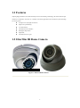
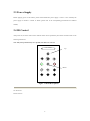
Day / Night IR Color Camera USER’S MANUAL Version 2.0.0 1 Thank you for purchasing our product. If there is any question or request, please do not hesitate to contact dealer. This manual is applicable to DS-2CC102P(N)-IR1(IR3)(IR5), DS-2CC112P(N)-IR1(IR3)(IR5), DS-2CC192P(N)-IR1(IR3)(IR5), DS-2CC102P(N)-IR, DS-2CC112P(N)-IR, DS-2CC192P(N)-IR, DS-2CC102P(N)-IRA, DS-2CC112P(N)-IRA, DS-2CC192P(N)-IRA, DS-2CC102P(N)-IRT, DS-2CC112P(N)-IRT, DS-2CC192P(N)-IRT, DS-2CC502P(N)-IR1(IR3), DS-2CC512P(N)-IR1(IR3), DS-2CC592P(N)-IR1(IR3), DS-2CC502P(N)-IR, DS-2CC512P(N)-IR, DS-2CC592P(N)-IR color IR cameras. This manual may contain several technically incorrect places or printing errors, and the content is subject to change without notice. The updates will be added into the new version of this manual. We will readily improve or update the products or procedures described in the manual. 2 Safety Instructions These instructions are intended to ensure that user can use the product correctly to avoid danger or property loss. The precaution measure is divided into “Warnings” and “Cautions” Warnings: Serious injury or death may cause if any of the warnings is neglected. Cautions: Injury or equipment damage may cause if any of the cautions is neglected. Warnings Follow these safeguards Cautions Follow these precautions to prevent serious injury or to prevent potential injury or death. material damage. Warnings 1. In the use of the product, you must be strict compliance with the electrical safety regulations of the nation and region. 2. Input voltage should meet both the SELV(Safety Extra Low Voltage) and the Limited Power Source with DC 12V according to the IEC60950-1 standard. Please refer to technical specifications for detail information. 3. Do not connect several devices to one power adapter as adapter overload may cause over-heat or fire hazard. 4. Please make sure that the plug is firmly connected on the power socket. 5. When the product is mounted on wall or ceiling, the device shall be firmly fixed. 6. If smoke, odor or noise rise from the device, turn off the power at once and unplug the power cable, and then please contact the service center. 7. If the product does not work properly, please contact your dealer or the nearest service center. Never attempt to disassemble the camera yourself. (We shall not assume any responsibility for problems caused by unauthorized repair or maintenance.) 3 Cautions: 1. Make sure the power supply voltage is correct before using the camera. 2. Do not drop the camera or subject it to physical shock. 3. Do not touch CCD (Charge Coupled Device) modules with fingers. If cleaning is necessary, use clean cloth with a bit of ethanol and wipe it gently. If the camera will not be used for an extended period, please turn on the lens cap to protect the CCD from dirt. 4. Do not aim the camera at the sun or extra bright places. A blooming or smear may occur otherwise (which is not a malfunction however), and affecting the endurance of CCD at the same time. 5. The CCD may be burned out by a laser beam, so when any laser equipment is on using, make sure that the surface of CCD will not be exposed to the laser beam. 6. Do not place the camera in extremely hot, cold(the operating temperature shall be-20℃~+60℃ ), dusty or damp locations, and do not expose it to high electromagnetism radiation. 7. To avoid heat accumulation, good ventilation is required for operating environment. 8. Keep the camera away from liquid while on using. 9. While on a delivery, the camera shall be packed in its original packing, or packing of the same texture. 10. Regular part replacement: a few parts (e.g. electrolytic capacitor) of the equipment shall be replaced regularly according to their average enduring time. The average time varies because of differences between operating environment and using history, so regular checking is recommended for all the users. Please contact with your dealer for more details. 4 Table of Contents C H A P T E R 1 .................................................................................................................................... 1 INTRODUCTION.................................................................................................................................. 1 1.1 FEATURES........................................................................................................................................... 2 1.2 10M/30M IR DOME CAMERA ............................................................................................................... 2 1.3 10M/30M/50M IR BOX CAMERA ........................................................................................................... 3 1.4 100M/110M IR BOX CAMERA .............................................................................................................. 4 1.5 IR VARIFOCAL BOX CAMERA .................................................................................................................. 4 C H A P T E R 2 .................................................................................................................................... 5 INSTALLATION .................................................................................................................................... 5 2.1 IR DOME CAMERA INSTALLATION DIAGRAM ............................................................................................. 6 2.2 REAR PANEL ....................................................................................................................................... 7 2.3 POWER SUPPLY ................................................................................................................................... 8 2.4 IR CONTROL ....................................................................................................................................... 8 C H A P T E R 3 .................................................................................................................................... 9 APPENDIX SPECIFICATIONS ................................................................................................................ 9 3.1 TABLE 1 ........................................................................................................................................... 10 3.2 TABLE 2 ........................................................................................................................................... 11 3.3 TABLE 3 ........................................................................................................................................... 12 3.4 TABLE 4 ........................................................................................................................................... 13 3.5 TABLE 5 ........................................................................................................................................... 14 3.6 TABLE 6 ........................................................................................................................................... 15 5 C HAPTE R 1 Introduction 1 1.1 Features Adopting high performance CCD and advanced print circuit board design technology, the camera features high resolution, low distortion, low noise, etc., and thus is extremely applicable to the surveillance system and image processing system. IR night vision, day/night surveillance; High color reproducibility; Low illumination; Automatic electronic Shutter; Backlight compensation High SNR; Automatic electronic gain; 1.2 10m/30m IR Dome Camera Figure. 1 Infrared Dome Camera 2 1.3 10m/30m/50m IR Box Camera Figure. 2 Infrared Box Camera 3 1.4 100m/110m IR Box Camera Figure. 3 Infrared Box Camera 1.5 IR Varifocal Box Camera Figure. 4 Infrared Varifocal Box Camera 4 C HAPTE R 2 Installation 5 Before mounting, please make sure that the device in the package is in good condition and all the assembly parts are complete. 2.1 IR Dome Camera Installation Diagram Figure. 5 Figure. 6 Remove the enclosure: Take out the camera from the packaging box (Figure. 5), and rotate the enclosure. When the convex part of the shell is exactly aligned with the concave part of the dome, remove the enclosure from the dome camera (Figure. 6). Figure. 7 Figure.8 Adjust the lens angle: After having removed the enclosure (Figure. 7), loosen the screws on the dome drive and adjust the lens angle to the desired position; finally tighten the screws on the drive (Fig. 8). 6 Figure 9 Figure 10 Note: The adjustable tilt angle range is 0 ° ~ 75 ° (Fig. 9). In-ceiling mounting: Tighten the screws by aligning the mounting holes on the dome base with holes in the ceiling to secure the dome camera in position. (Fig. 10). 2.2 Rear Panel Figure. 11 Wiring Diagram 7 2.3 Power Supply Before applying power to the camera, please check whether the power supply is correct or not. Generally the power supply for camera is 12VDC or 24VAC (please refer to the corresponding specifications for different models). 2.4 IR Control After power-on, the focus control of IR varifocal camera can be operated by the remote controller. Refer to the following instructions: Note: Only the up and down keys are operable; the others are reserved. CCTV CAMERA Up 1 1 1 1 + Down F1 F2 F3 F4 Figure. 11 Panel Descriptions UP: Zoom out. Down: Zoom in. 8 C HAPTE R 3 Appendix Specifications 9 3.1 Table 1 Model Parameter DS-2CC102P(N)-IR1(IR3)(IR5) DS-2CC112P(N)-IR1(IR3)(IR5) Image Sensor 1/3 inch SONY Super HAD CCD Signal System PAL/NTSC Effective Pixels DS-2CC192P(N)-IR1(IR3)(IR5) PAL:500(H)×582(V) PAL:752(H)×582(V) NTSC:510(H)×492(V) NTSC:768(H) ×494(V) Min. Illumination 0.1Lux @ F1.2(0 LUX with IR) Electronic Shutter 1/50(1/60)s~1/100,000s Lens “-IR1” Series: 6mm (3.6mm optional) “-IR3” Series: 12mm(3.6mm,6mm,8mm,16mm optional) “-IR5” Series: 16mm(3.6mm,6mm,8mm,12mm optional) Horizontal Resolution 420 TVL 480TVL 540TVL Synchronous Internal Synchronization Video Output 1Vp-p Composite Output(75Ω/BNC) S/N Ratio More than 48 dB BLC ON Working Temperature -10℃~60℃ Water and Dust Resistance IR Distance IP66 10m/30m/50m”-IR1” Series: IR Illuminators up to10 meters. “-IR3” Series: IR Illuminators up to30 meters. “-IR5” Series: IR Illuminators up to 50 meters Power Supply 12V DC, ±10% Power Consumption IR1: 3W MAX Dimension(mm) IR1: 76.5×73×125.5 Weight IR1: 600g 10 IR3 : 6W MAX IR5:8W MAX IR3/IR5 : 86.5×83×160 IR3/IR5: 1000g 3.2 Table 2 Model Parameter DS-2CC102P(N)-IR DS-2CC112P(N)-IR DS-2CC192P(N)-IR Image Sensor 1/3 inch SONY Super HAD CCD Signal System PAL/NTSC Effective Pixels PAL:500(H)×582(V) PAL:752(H)×582(V) NTSC:510(H)×492(V) NTSC:768(H)×494(V) Min. Illumination 0.1Lux @ F1.2(0 LUX with IR) Electronic Shutter 1/50(1/60)s~1/100,000s Lens Horizontal Resolution 6mm(2.8mm 3.6mm Optional) 420 TVL 480TVL 540TVL Synchronous Internal Synchronization Video Output 1Vp-p Composite Output(75Ω/BNC) S/N Ratio More than 48 dB BLC ON IR Distance 10-20m Working Temperature -10℃~60℃ Water and Dust Resistance IP66 Power Supply DC12V±10% Power Consumption 3W MAX Dimension (mm) Φ58×80.5 Weight 250g 11 3.3 Table 3 Model Parameter DS-2CC102P(N)-IRA DS-2CC112P(N)-IRA DS-2CC192P(N)-IRA Image Sensor 1/3 inch SONY Super HAD CCD Signal System PAL/NTSC Effective Pixels PAL:500(H)×582(V) PAL:752(H)×582(V) NTSC:510(H)×492(V) NTSC:768(H)×494(V) Min. Illumination 0.1Lux @ F1.2(0 LUX with IR) Electronic Shutter 1/50(1/60)s~1/100,000s Lens 25mm(16mm Optional) Horizontal Resolution 420 TVL 480TVL Synchronous Internal Synchronization Video Output 1Vp-p Composite Output(75Ω/BNC) S/N Ratio More than 48 dB BLC ON IR Distance 100-110m Working Temperature -10℃~60℃ Water and Dust Resistance IP66 Power Supply AC24V±10%(DC12V±10% Custom) Power Consumption 15W Dimension (mm) 255×177×95 Weight 2500g 12 540TVL 3.4 Table 4 Model Parameter DS-2CC102P(N)-IRT DS-2CC112P(N)-IRT DS-2CC192P(N)-IRT Image Sensor 1/3 inch SONY CCD Signal System PAL/NTSC Effective Pixels PAL:500(H)×582(V) PAL:752(H)×582(V) NTSC:510(H)×492(V) NTSC:768(H)×494(V) Min. Illumination 0.1Lux @ F1.2(0 LUX with IR) Electronic Shutter 1/50(1/60)s~1/100,000s Lens Horizontal Resolution 4-9 mm(8-20 mm Optional) zoom lens, IR control 420 TVL 480TVL Synchronous Internal Synchronization Video Output 1Vp-p Composite Output(75Ω/BNC) S/N Ratio More than 48 dB BLC ON IR Distance 30-40m Working Temperature -10℃~60℃ Water and Dust Resistance IP66 Power Supply AC24V/DC12V, ±10% Power Consumption 12W MAX Dimension (mm) 190×104.2×87.8 Weight 1000g 13 540TVL 3.5 Table 5 Model Parameter DS-2CC502P(N)-IR1(IR3) DS-2CC512P(N)-IR1(IR3) Image Sensor 1/3 inch SONY Super HAD CCD Signal System PAL/NTSC Effective Pixels DS-2CC592P(N)-IR1(IR3) PAL:500(H)×582(V) PAL:752(H)×582(V) NTSC:510(H)×492(V) NTSC:768(H) ×494(V) Min. Illumination 0.1Lux @ F1.2(0 LUX with IR) Electronic Shutter 1/50(1/60)s~1/100,000s Lens “-IR1”: 6mm (3.6mm,2.8mm Optional) “-IR3”: 12mm(3.6mm,6mm,8mm,16mm Optional) Horizontal Resolution 420 TVL 480TVL Synchronous Internal Synchronization Video Output 1Vp-p Composite Output(75Ω/BNC) S/N Ratio More than 48 dB BLC ON Working Temperature -10℃~60℃ Water and Dust Resistance IP66 “-IR1”: 10-20m IR Distance “-IR3” : 30-40m Power Supply DC12V, ±10% Power Consumption IR1: 3W MAX Dimension (mm) IR3: 6W MAX 129×69 Weight 700g 14 540TVL 3.6 Table 6 Model Parameter DS-2CC502P(N)-IR DS-2CC512P(N)-IR Image Sensor 1/3 inch SONY Super HAD CCD Signal System PAL/NTSC Effective Pixels PAL:500(H)×582(V) PAL:752(H)×582(V) NTSC:510(H)×492(V) NTSC:768(H) ×494(V) Min. Illumination 0.1Lux @ F1.2(0 LUX with IR) Electronic Shutter 1/50(1/60)s~1/100,000s Lens Horizontal Resolution DS-2CC592P(N)-IR 6mm (3.6mm,2.8mm Optional) 420 TVL 480TVL Synchronous Internal Synchronization Video Output 1Vp-p Composite Output(75Ω/BNC) S/N Ratio More than 48 dB BLC ON Working Temperature -10℃~60℃ Water and Dust Resistance IP66 IR Distance 10-20m Power Supply DC12V, ±10% Power Consumption 3W MAX Dimension (mm) 89.5×60 Weight 400g 15 540TVL