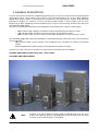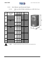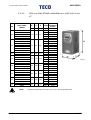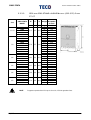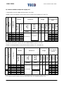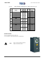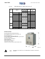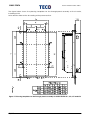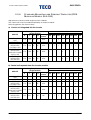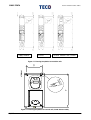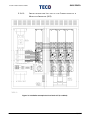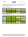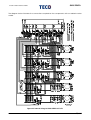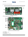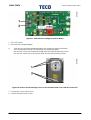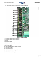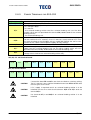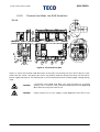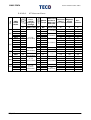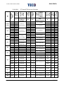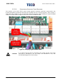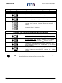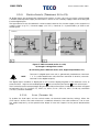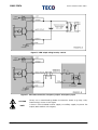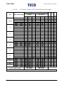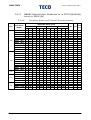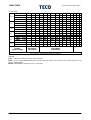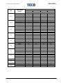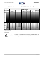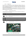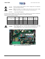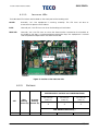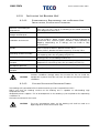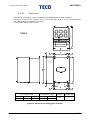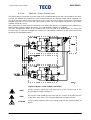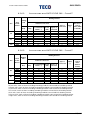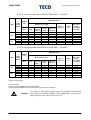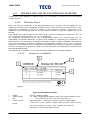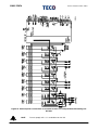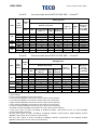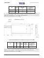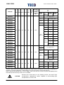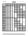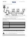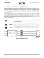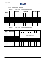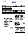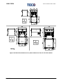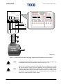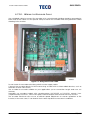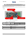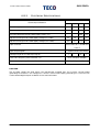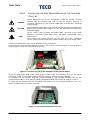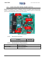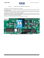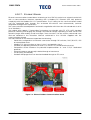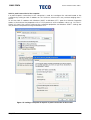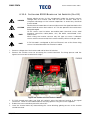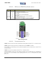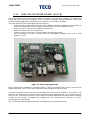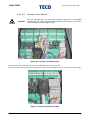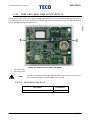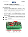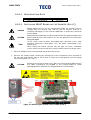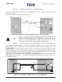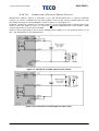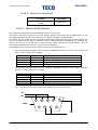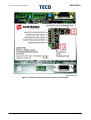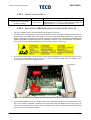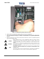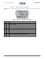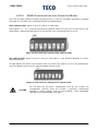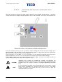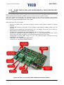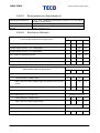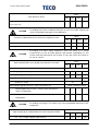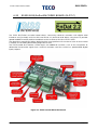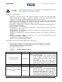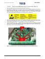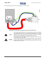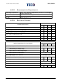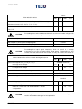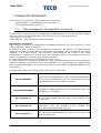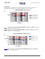
1
• 15P0102B1 • SINUS PENTA MULTIFUNCTION AC DRIVE USER MANUAL - Installation Instructions - Issued on 29/03/2012 R.06 English • This manual is integrant and essential to the product. Carefully read the instructions contained herein as they provide important hints for use and maintenance safety. • This device is to be used only for the purposes it has been designed to. Other uses should be considered improper and dangerous. The manufacturer is not responsible for possible damages caused by improper, erroneous and irrational uses. • TECO is responsible for the device in its original setting. • Any changes to the structure or operating cycle of the device must be performed or authorized by the Engineering Department of TECO. • TECO assumes no responsibility for the consequences resulting by the use of non-original spare-parts. • TECO reserves the right to make any technical changes to this manual and to the device without prior notice. If printing errors or similar are detected, the corrections will be included in the new releases of the manual. • The information contained herein is the property of TECO and cannot be reproduced. TECO enforces its rights on the drawings and catalogues according to the law. TECO Electric & Machinery Co., Ltd. No.3-1, Yuan Cyu St, Nan-Kang, Taipei 11503, Taiwan Tel. +886-2-6615-9111 – Fax + 886-2-6615-1033 www.teco.com.tw/sa REVISION INDEX The following subjects covered in this User Manual (Installation Instructions) R.06 have been added, changed or suppressed with respect to the previous revision R.05. GENERAL Declarations of conformity removed as they are available for download from TECO website. Discharging time increased from 15 to 20 minutes. Min. operating temperature extended from 0°C to -10°C. Max. operating altitude reduced from 4000m to 2000m a.s.l. Earthing systems configuration (TN-IT) added. Specifications about Protective Earthing conductor added. MTBF value added. 6T Voltage Class range extended from 600÷690 Vac to 575÷690 Vac. UL-Fuses tables modified according to the latest reviews from UL. Surge Protection Devices (SPDs) section for 2T Voltage Class added. Sections covering UL-approved Fuses modified according to UL recommendations. Wiring Diagram revised: 5A instead of 3A for the Output Relays; START Input configurable and not fixed to MDI1. Picture about wiring diagram of the keypad remoting kit fixed (9VDC instead of 9VAC). 60/120Hz Max. output frequency detailed for du/dt inductors. Dimensions for cabinets revised. MODELS New S84/S90 4T/5T/6T models added together with their additional components (reactors and braking resistors). New S12/S14/S22/S32 5T/6T models added together with their additional components (reactors and braking resistors). Out-of-production S40/S50 4T models removed together with their additional components (reactors and braking resistors). Some values changed in Light/Standard/Heavy/Strong Application Tables. MODULAR DRIVES Caution note about DC reactor for modular sizes added. Caution note about connection busbars in modular sizes added. Section about 12-pulse revised. Table summarising modular Sizes added. Indications for C-U, C-V, C-W from CN3 to CN6 in the internal connections tables for S65-70 and S64 fixed. BRAKING UNITS Average and maximum current definitions for external braking units added. Swapped description for RV2 and RV3 in BU200 braking unit. BU600/700: note about unavailable functions added. Recommended cable cross-section for output relays added. Description about max. duration of insertion for braking resistors reworded. OPTION BOARDS Option boards ES860/ES861/ES950 for synchronous motors added. Option board ES851 for Real Time Clock function added. Number of digital and analog inputs for ES847 option board fixed. Encoder/frequency inputs XMDI6..8 for ES870 option board correctly described. Changed all the notes about mechanical compatibility between ES919 and the boards on SLOT C. ES914 board: minimum baud rate is 4800bps. 2/441 INSTALLATION INSTRUCTIONS SINUS PENTA 0. TABLE OF CONTENTS REVISION INDEX ..................................................................................................................................................................... 2 0. TABLE OF CONTENTS .................................................................................................................................................. 3 0.1. Index of Figures................................................................................................................................... 10 1. GENERAL DESCRIPTION ............................................................................................................................................ 14 1.1. FEATURE LIST ......................................................................................................................................... 15 1.2. SPECIAL APPLICATIONS AVAILABLE ON SINUS PENTA INVERTERS .............................................. 16 2. CAUTION STATEMENTS ............................................................................................................................................ 17 3. EQUIPMENT DESCRIPTION AND INSTALLATION............................................................................................... 19 3.1. PRODUCTS COVERED IN THIS MANUAL .......................................................................................... 19 3.2. DELIVERY CHECK ................................................................................................................................ 20 3.2.1. Inverter Nameplate .................................................................................................................. 22 3.3. INSTALLING THE EQUIPMENT ............................................................................................................. 23 3.3.1. Environmental Requirements for the Equipment Installation, Storage and Transport. 23 3.3.2. Air Cooling .................................................................................................................................. 25 3.3.3. Size, Weight and Dissipated Power ....................................................................................... 29 3.3.3.1. IP20 and IP00 STAND-ALONE Models (S05–S60) Class 2T ............................................... 29 3.3.3.2. IP20 and IP00 STAND-ALONE Models (S05–S60) Class 4T ............................................... 30 3.3.3.3. IP20 and IP00 STAND-ALONE Models (S12–S52) Class 5T-6T .......................................... 31 3.3.3.4. Modular IP00 STAND-ALONE Models (S64–S90) .............................................................. 32 3.3.3.5. IP54 STAND-ALONE Models (S05–S30) Class 2T ................................................................ 39 3.3.3.6. IP54 STAND-ALONE Models (S05–S30) Class 4T ................................................................ 40 3.3.3.7. IP54 STAND-ALONE Models (S12–S32) Class 5T-6T ........................................................... 41 3.3.3.8. IP54 BOX Models (S05–S20) Class 2T .................................................................................. 42 3.3.3.9. IP54 BOX Models (S05–S20) Class 4T .................................................................................. 43 3.3.3.10. IP24 and IP54 Cabinet Models (S15–S90) .................................................................... 44 3.3.4. Standard Mounting and Piercing Templates (IP20 and IP00 Stand-Alone Models S05– S60) 47 3.3.5. Through-Panel Assembly and Piercing Templates (IP20 and IP00 Stand-Alone Models S05–S52) ...................................................................................................................................................... 49 3.3.5.1. SINUS PENTA S05 .................................................................................................................... 49 3.3.5.2. SINUS PENTA S12 .................................................................................................................... 51 3.3.5.3. SINUS PENTA S14 .................................................................................................................... 53 3.3.5.4. SINUS PENTA S15–S20–S30 .................................................................................................... 55 3.3.5.5. SINUS PENTA S22–S32 ............................................................................................................ 56 3.3.5.6. SINUS PENTA S41–S42–S51–S52 ............................................................................................ 58 3.3.6. Standard Mounting and Piercing Templates (IP00 Modular Models S64–S90) ............. 60 3.3.6.1. Installation and Lay-out of the Connections of a Modular Inverter (S65) ................. 62 3.3.7. Standard Mounting and Piercing Templates (IP54 Stand-Alone Models S05–S32) ...... 63 3.4. POWER CONNECTIONS ..................................................................................................................... 64 3.4.1. Wiring Diagram for inverters S05–S60 .................................................................................... 66 3.4.2. Wiring Diagram for Modular Inverters S64–S90 .................................................................... 68 3.4.2.1. External Connections for Modular Inverters S65 and S70 ............................................. 68 3.4.2.2. External Connections for Modular Inverters S64 ............................................................. 69 3.4.2.3. External Connections for Modular Inverters S74, S75 and S80 ..................................... 70 3.4.2.4. External Connections for Modular inverters S84 and S90 ............................................. 70 3.4.2.5. 12-pulse Connection for Modular Inverters ..................................................................... 70 3.4.2.6. Internal Connections for Modular Inverters S65 and S70 .............................................. 72 3.4.2.7. Internal Connections for Modular Inverters S64 ............................................................. 81 3.4.2.8. Internal Connections for Modular Inverters S74, S75 and S80 ...................................... 85 3.4.2.9. Internal Connections for Modular Inverters S84 and S90 .............................................. 85 3.4.3. Power Terminals for S05–S52 .................................................................................................... 86 3.4.4. Power Terminals Modified for a DC Reactor ....................................................................... 89 3/441 3.4.5. Connection Bars for S60 Inverters .......................................................................................... 90 3.4.6. Connection Bars for Modular Inverters S64–S70 .................................................................. 91 3.4.7. Connection Bars for Modular Inverters S74–S80 .................................................................. 92 3.4.8. Connection Bars for Modular Inverters S84–S90 .................................................................. 93 3.4.9. Auxiliary Power Supply Terminals ........................................................................................... 94 3.4.10. Cross-sections of the Power Cables and Sizes of the Protective Devices ..................... 94 3.4.10.1. 2T Voltage Class ............................................................................................................... 95 3.4.10.2. UL-approved Fuses - 2T Voltage Class ......................................................................... 97 3.4.10.3. UL-approved Surge Protective Devices (SPD) - 2T Voltage Class .......................... 98 3.4.10.4. 4T Voltage Class ............................................................................................................... 99 3.4.10.5. UL-approved Fuses - 4T Voltage Class ....................................................................... 102 3.4.10.6. 5T and 6T Voltage Classes............................................................................................ 104 3.4.10.7. UL-approved Fuses - 5T and 6T Voltage Classes...................................................... 106 3.4.11. Inverter and Motor Ground Connection ........................................................................... 107 3.5. CONTROL TERMINALS ...................................................................................................................... 108 3.5.1. Main Features .......................................................................................................................... 108 3.5.1.1. Gaining Access to Control Terminals and Power Terminals in IP20 and IP00 Models 112 3.5.1.2. Gaining Access to Control Terminals and Power Terminals in IP54 Models ............ 113 3.5.1.3. Grounding Shielded Cable Braiding .............................................................................. 115 3.5.2. Control Board Signals and Programming .......................................................................... 116 3.5.2.1. Display and Indicator LEDs ............................................................................................... 117 3.5.2.2. DIP-switches ......................................................................................................................... 120 3.5.2.3. Configuration Jumpers ...................................................................................................... 122 3.5.3. Digital Inputs (Terminals 14 to 21)......................................................................................... 123 3.5.3.1. Start (Terminal 14) ............................................................................................................... 123 3.5.3.2. Enable (Terminal 15) .......................................................................................................... 124 3.5.3.3. Reset (Terminal 16) ............................................................................................................. 124 3.5.3.4. Connecting the Encoder and Frequency Input (Terminals 19 to 21) ...................... 125 3.5.3.5. Technical Sheet for Digital Inputs .................................................................................... 126 3.5.4. Analog Inputs (Terminals 1 to 9) ........................................................................................... 127 3.5.4.1. REF Single-ended Reference Input (Terminal 2) ........................................................... 128 3.5.4.2. Differential Auxiliary Inputs (Terminals 5–8) .................................................................... 129 3.5.4.3. Motor Thermal Protection Input (PTC, Terminals 7-8)................................................... 131 3.5.4.4. Technical Sheet for Analog Inputs .................................................................................. 133 3.5.5. Digital Outputs (Terminals 24 to 34) ..................................................................................... 134 3.5.5.1. Push-Pull Output MDO1 and Wiring Diagrams (Terminals 24 to 26) .......................... 134 3.5.5.2. Open-collector MDO2 Output and Wiring Diagrams (Terminals 27-28) .................. 136 3.5.5.3. Relay Outputs (Terminals 29..34) ..................................................................................... 137 3.5.5.4. Technical Sheet for Digital Outputs ................................................................................ 138 3.5.6. Analog Outputs (Terminals 10 to 13) ................................................................................... 139 3.5.6.1. Technical Sheet for Analog Outputs .............................................................................. 139 3.6. OPERATING AND REMOTING THE KEYPAD ................................................................................... 140 3.6.1. Indicator LEDs on the Display/Keypad ............................................................................... 140 3.6.2. Function Keys ........................................................................................................................... 141 3.6.3. Setting the Operating Mode ................................................................................................ 143 3.6.3.1. Adjusting the Display Contrast......................................................................................... 143 3.6.3.2. Adjusting the Display Contrast, Back-light and Buzzer................................................ 143 3.6.4. Remoting the Display/Keypad ............................................................................................. 144 3.6.5. Using the Display/Keypad for Parameter Transfer ............................................................ 147 3.7. SERIAL COMMUNICATIONS ............................................................................................................ 148 3.7.1. General Features .................................................................................................................... 148 3.7.2. Direct Connection .................................................................................................................. 149 3.7.3. Multidrop Network Connection ........................................................................................... 149 3.7.3.1. Connection ......................................................................................................................... 149 3.7.3.2. Line Terminators .................................................................................................................. 152 3.7.4. How to Use Isolated Serial Board ES822 (Optional) .......................................................... 153 3.7.5. The Software ............................................................................................................................ 153 4/441 INSTALLATION INSTRUCTIONS SINUS PENTA 3.7.6. Serial communication ratings ............................................................................................... 153 3.8. AUXILIARY POWER SUPPLY .............................................................................................................. 154 4. START UP .................................................................................................................................................................... 155 4.1. “IFD” Motor Control ......................................................................................................................... 156 4.2. “VTC” Motor Control ....................................................................................................................... 158 4.3. “FOC” Motor Control ...................................................................................................................... 160 4.4. “SYN” Motor Control ........................................................................................................................ 163 5. TECHNICAL SPECIFICATIONS ................................................................................................................................ 164 5.1. CHOOSING THE PRODUCT .............................................................................................................. 166 5.1.1. LIGHT Applications: Overload up to 120% (60/120s) or up to 144% (3s) ....................... 169 5.1.1.1. Technical Sheet for 2T and 4T Voltage Classes ............................................................ 169 5.1.1.2. Technical Sheet for 5T and 6T Voltage Classes ............................................................ 171 5.1.2. STANDARD Applications: Overload up to 140% (60/120s) or up to 168% (3s) ............. 172 5.1.2.1. Technical Sheet for 2T and 4T Voltage Classes ............................................................ 172 5.1.2.2. Technical Sheet for 5T and 6T Voltage Classes ............................................................ 174 5.1.3. HEAVY Applications: Overload up to 175% (60/120s) or up to 210% (3s) .................... 175 5.1.3.1. Technical Sheet for 2T and 4T Voltage Classes ............................................................ 175 5.1.3.2. Technical Sheet for 5T and 6T Voltage Classes ............................................................ 177 5.1.4. STRONG Applications: Overload up to 200% (60/120s) or up to 240% (3s).................. 178 5.1.4.1. Technical Sheet for 2T and 4T Voltage Classes ............................................................ 178 5.1.4.2. Technical Sheet for 5T and 6T Voltage Classes ............................................................ 180 5.2. CARRIER FREQUENCY SETTING ....................................................................................................... 181 5.2.1. IP20 and IP00 Models – Class 2T-4T ...................................................................................... 181 5.2.2. IP20 and IP00 Models – Class 5T-6T ...................................................................................... 183 5.2.3. IP54 Models – Class 2T-4T ....................................................................................................... 185 5.2.4. IP54 Models – Class 5T-6T ....................................................................................................... 185 5.3. OPERATING TEMPERATURES BASED ON APPLICATION CATEGORY ......................................... 186 6. ACCESSORIES ............................................................................................................................................................. 189 6.1. RESISTIVE BRAKING ........................................................................................................................... 189 6.1.1. Braking Resistors ...................................................................................................................... 190 6.1.1.1. Applications with DUTY CYCLE 10% - Class 2T ............................................................... 190 6.1.1.2. Applications with DUTY CYCLE 20% - Class 2T ............................................................... 191 6.1.1.3. Applications with DUTY CYCLE 50% - Class 2T ............................................................... 192 6.1.1.4. Applications with DUTY CYCLE 10% - Class 4T ............................................................... 193 6.1.1.5. Applications with DUTY CYCLE 20% - Class 4T ............................................................... 194 6.1.1.6. Applications with DUTY CYCLE 50% - Class 4T ............................................................... 195 6.1.1.7. Applications with DUTY CYCLE 10% - Class 5T ............................................................... 196 6.1.1.8. Applications with DUTY CYCLE 20% - Class 5T ............................................................... 197 6.1.1.9. Applications with DUTY CYCLE 50% - Class 5T ............................................................... 198 6.1.1.10. Applications with DUTY CYCLE 10% - Class 6T .......................................................... 199 6.1.1.11. Applications with DUTY CYCLE 20% - Class 6T .......................................................... 200 6.1.1.12. Applications with DUTY CYCLE 50% - Class 6T .......................................................... 201 6.2. BRAKING UNIT (BU200) for S60 ........................................................................................................ 202 6.2.1. Delivery Check ........................................................................................................................ 202 6.2.1.1. Nameplate for BU200 ........................................................................................................ 203 6.2.2. Operation ................................................................................................................................. 204 6.2.2.1. Configuration Jumpers ...................................................................................................... 204 6.2.2.2. Adjusting Trimmers .............................................................................................................. 205 6.2.2.3. Indicator LEDs ...................................................................................................................... 206 6.2.3. Ratings....................................................................................................................................... 206 6.2.4. Installing the Braking Unit ....................................................................................................... 207 6.2.4.1. Environmental Requirements for the Braking Unit Installation, Storage and Transport 207 6.2.4.2. Cooling System and Dissipated Power .......................................................................... 207 6.2.4.3. Mounting .............................................................................................................................. 208 6.2.4.4. Lay-Out of Power Terminals and Signal Terminals ........................................................ 209 6.2.4.5. Wiring .................................................................................................................................... 211 5/441 6.2.4.6. Master – Slave Connection .............................................................................................. 212 6.2.5. Braking Resistors for BU200 2T ................................................................................................ 213 6.2.5.1. Applications with DUTY CYCLE 10% - Class 2T ............................................................... 213 6.2.5.2. Applications with DUTY CYCLE 20% - Class 2T ............................................................... 214 6.2.5.3. Applications with DUTY CYCLE 50% - Class 2T ............................................................... 214 6.2.6. Braking Resistors for BU200 4T ................................................................................................ 215 6.2.6.1. Applications with DUTY CYCLE 10% - Class 4T ............................................................... 215 6.2.6.2. Applications with DUTY CYCLE 20% - Class 4T ............................................................... 216 6.2.6.3. Applications with DUTY CYCLE 50% - Class 4T ............................................................... 216 6.3. BRAKING UNITS FOR S41–S51 (BU700 2T-4T) AND S42–S52 (BU600 5T-6T) ................................ 217 6.3.1. Delivery Check ........................................................................................................................ 217 6.3.1.1. Nameplate for BU600 ........................................................................................................ 217 6.3.2. Operating Mode ..................................................................................................................... 218 6.3.3. Specifications .......................................................................................................................... 220 6.3.4. Installing the Braking Unit ....................................................................................................... 220 6.3.4.1. Environmental Requirements for the Braking Unit Installation, Storage and Transport 220 6.3.4.2. Mounting the Braking Unit ................................................................................................ 221 6.3.4.3. Lay-Out of Power Terminals and Signal Terminals ........................................................ 222 6.3.4.4. Wiring Diagram ................................................................................................................... 226 6.3.5. Braking Resistors for BU700 2T-4T ........................................................................................... 227 6.3.5.1. Applications with DUTY CYCLE 10% - Class 2T ............................................................... 227 6.3.5.2. Applications with DUTY CYCLE 20% - Class 2T ............................................................... 227 6.3.5.3. Applications with DUTY CYCLE 50% - Class 2T ............................................................... 228 6.3.5.4. Applications with DUTY CYCLE 10% - Class 4T ............................................................... 228 6.3.5.5. Applications with DUTY CYCLE 20% - Class 4T ............................................................... 229 6.3.5.6. Applications with DUTY CYCLE 50% - Class 4T ............................................................... 229 6.3.6. Braking Resistors for BU600 5T-6T ........................................................................................... 230 6.3.6.1. Applications with DUTY CYCLE 10% - Class 5T ............................................................... 230 6.3.6.2. Applications with DUTY CYCLE 20% - Class 5T ............................................................... 230 6.3.6.3. Applications with DUTY CYCLE 50% - Class 5T ............................................................... 231 6.3.6.4. Applications with DUTY CYCLE 10% - Class 6T ............................................................... 231 6.3.6.5. Applications with DUTY CYCLE 20% - Class 6T ............................................................... 232 6.3.6.6. Applications with DUTY CYCLE 50% - Class 6T ............................................................... 232 6.4. BRAKING UNIT BU1440 FOR MODULAR INVERTERS...................................................................... 233 6.4.1. Delivery Check ........................................................................................................................ 233 6.4.1.1. Nameplate for BU1440 ...................................................................................................... 233 6.4.2. Operation ................................................................................................................................. 235 6.4.3. Ratings....................................................................................................................................... 235 6.4.4. Installing the Braking Unit ....................................................................................................... 235 6.4.4.1. Environmental Requirements for the Braking Unit Installation, Storage and Transport 235 6.4.4.2. Mounting the Braking Unit ................................................................................................ 237 6.4.4.3. Wiring Diagram ................................................................................................................... 238 6.4.5. Braking Resistors for BU1440 4T .............................................................................................. 244 6.4.5.1. Applications with DUTY CYCLE 10% - Class 4T ............................................................... 244 6.4.5.2. Applications with DUTY CYCLE 20% - Class 4T ............................................................... 245 6.4.5.3. Applications with DUTY CYCLE 50% - Class 4T ............................................................... 245 6.4.6. Braking Resistors for BU1440 5T-6T ......................................................................................... 246 6.4.6.1. Applications with DUTY CYCLE 10% - Class 5T ............................................................... 246 6.4.6.2. Applications with DUTY CYCLE 20% - Class 5T ............................................................... 247 6.4.6.3. Applications with DUTY CYCLE 50% - Class 5T ............................................................... 247 6.4.6.4. Applications with DUTY CYCLE 10% - Class 6T ............................................................... 248 6.4.6.5. Applications with DUTY CYCLE 20% - Class 6T ............................................................... 248 6.4.6.6. Applications with DUTY CYCLE 50% - Class 6T ............................................................... 249 6.4.7. Available Braking Resistors .................................................................................................... 250 6.4.7.1. 350W Models (IP55) ............................................................................................................ 250 6.4.7.2. 1300W Models (IP33) .......................................................................................................... 251 6/441 INSTALLATION INSTRUCTIONS SINUS PENTA 6.4.7.3. IP55 Models from 1100W to 2200W ................................................................................. 252 6.4.7.4. IP20 Models from 4kW-8kW-12kW .................................................................................... 254 6.4.7.5. IP23 Boxes from 4kW to 64kW ........................................................................................... 256 6.5. KEYPAD REMOTING KITS .................................................................................................................. 261 6.5.1. Remoting the Keypad on the Cabinet .............................................................................. 261 6.5.2. Remoting a Keypad Controlling Multiple Inverters .......................................................... 261 6.5.2.1. Kit Component Parts.......................................................................................................... 261 6.5.2.2. Operating Conditions ........................................................................................................ 262 6.5.2.3. Connecting the Keypad................................................................................................... 262 6.5.2.4. The Communications Protocol ........................................................................................ 263 6.5.2.5. Connection ......................................................................................................................... 265 6.6. INDUCTORS ........................................................................................................................................ 266 6.6.1. Input Inductors......................................................................................................................... 266 6.6.2. Output Inductors (DU/DT Filters) ........................................................................................... 269 6.6.3. Applying the Inductor to the Inverter ................................................................................. 270 6.6.3.1. Class 2T – AC and DC Inductors ...................................................................................... 270 6.6.3.2. Class 4T – AC and DC Inductors ...................................................................................... 271 6.6.3.3. Class 5T-6T – AC and DC Inductors ................................................................................. 272 6.6.4. Inductance Ratings ................................................................................................................ 273 6.6.4.1. Class 2T-4T – AC 3-Phase Inductors ................................................................................. 273 6.6.4.2. Class 5T-6T – AC 3-Phase Inductors ................................................................................. 273 6.6.4.3. Class 2T-4T – DC Inductors ................................................................................................ 275 6.6.4.4. Class 5T-6T – DC Inductors ................................................................................................ 275 6.6.4.5. Class 2T, 4T, 5T, 6T – 3-Phase DU/DT INDUCTORS ........................................................... 277 6.6.5. Class 2T – 3-PHASE AC INDUCTORS IN IP54 CABINET ........................................................ 278 6.6.6. Class 4T – 3-PHASE AC INDUCTORS IN IP54 CABINET ........................................................ 279 6.6.7. Class 5T-6T – 3-PHASE AC INDUCTORS IN IP54 CABINET ................................................... 280 6.6.8. OUTPUT SINGLE-PHASE INDUCTORS FOR MODULAR INVERTERS S75, S80 and S90 ...... 282 6.6.8.1. AC single-phase INDUCTORS – CLASS 4T-5T-6T ............................................................. 282 6.6.9. Sinusoidal Filters ....................................................................................................................... 283 6.7. ES836/2 ENCODER BOARD (SLOT A) ............................................................................................. 284 6.7.1. Identification Data ................................................................................................................. 284 6.7.2. Environmental Requirements................................................................................................ 284 6.7.3. Electrical Specifications......................................................................................................... 285 6.7.4. Installing ES836/2 Encoder Board on the Inverter (Slot A) ............................................... 286 6.7.5. Terminals in Encoder Board .................................................................................................. 287 6.7.6. Configuration DIP-switches ................................................................................................... 287 6.7.7. Jumper Selecting the Type of Encoder Supply ................................................................. 288 6.7.8. Adjusting Trimmer .................................................................................................................... 289 6.7.9. Encoder Wiring and Configuration ..................................................................................... 289 6.7.10. Wiring the Encoder Cable..................................................................................................... 294 6.8. ES913 LINE DRIVER ENCODER BOARD (SLOT A) .......................................................................... 295 6.8.1. Identification Data ................................................................................................................. 295 6.8.2. Environmental Requirements................................................................................................ 295 6.8.3. Electrical Specifications......................................................................................................... 296 6.8.4. Installing the Line Driver Board on the Inverter (Slot A) ................................................... 297 6.8.5. Terminals in the Line Driver Encoder Board........................................................................ 298 6.8.6. Configuration DIP-switches ................................................................................................... 298 6.8.7. Encoder Supply Selection Jumper ...................................................................................... 299 6.8.8. Adjusting Trimmer .................................................................................................................... 300 6.9. ES822 ISOLATED SERIAL BOARD (SLOT B) ...................................................................................... 301 6.9.1. Identification Data ................................................................................................................. 301 6.9.2. Environmental Requirements................................................................................................ 301 6.9.3. Electrical Features................................................................................................................... 302 6.9.4. Installing ES822 Board on the Inverter (Slot B).................................................................... 303 6.9.5. Setting ES822 Board ................................................................................................................ 304 6.9.5.1. Jumper for RS232/RS485 Selection .................................................................................. 304 7/441 6.9.5.2. DIP-switch for RS485 Terminator ....................................................................................... 305 6.10. OPTION BOARDS FOR FIELDBUS (SLOT B)...................................................................................... 306 6.10.1. Identification Data ................................................................................................................. 307 6.10.2. Installing the FieldBus board on the Inverter (Slot B) ........................................................ 307 6.10.3. Fieldbus PROFIBUS-DP® Board ............................................................................................... 310 6.10.3.1. Profibus® Fieldbus Connector ...................................................................................... 311 6.10.3.2. Configuration of the Profibus-DP Communications Board .................................... 311 6.10.3.3. Connection to the Fieldbus ......................................................................................... 313 6.10.4. PROFIdrive Fieldbus Board®................................................................................................... 314 6.10.5. DeviceNet Fieldbus Board® .................................................................................................. 314 6.10.5.1. DeviceNet® Fieldbus Terminals .................................................................................... 315 6.10.5.2. Board Configuration ..................................................................................................... 315 6.10.5.3. Connection to the Fieldbus ......................................................................................... 316 6.10.6. CANopen® Fieldbus Board.................................................................................................... 318 6.10.6.1. CANopen Fieldbus® Connector ................................................................................. 319 6.10.6.2. Board Configuration ..................................................................................................... 319 6.10.6.3. Connection to the Fieldbus ......................................................................................... 320 6.10.7. Ethernet Board ........................................................................................................................ 321 6.10.7.1. Ethernet Connector ...................................................................................................... 322 6.10.7.2. Connection to the Network......................................................................................... 322 6.10.7.3. Board Configuration ..................................................................................................... 324 6.10.8. Status LEDs ................................................................................................................................ 329 6.10.8.1. LEDs for Fieldbus Interface CPU Diagnostics ............................................................ 329 6.10.8.2. LEDs for PROFIBUS-DP® Board Diagnostics ................................................................ 330 6.10.8.3. LEDs for DeviceNet® Board Diagnostics .................................................................... 330 6.10.8.4. LEDs for CANopen® Board Diagnostics ..................................................................... 331 6.10.8.5. LEDs for Ethernet Board Diagnostics .......................................................................... 331 6.10.9. Environmental Requirements Common to All Boards ..................................................... 331 6.11. ES919 COMMUNICATIONS BOARD (SLOT B) ................................................................................ 332 6.11.1. Identification Data ................................................................................................................. 332 6.11.2. Environmental Requirements Common to all Boards...................................................... 332 6.11.3. Electrical Features Common to All Boards ........................................................................ 332 6.11.4. Installing ES919 Board on the Inverter (Slot B).................................................................... 333 6.11.5. ES919 Board for Metasys® N2 ................................................................................................ 334 6.11.5.1. CONFIGURATION ........................................................................................................... 334 6.11.5.2. RS485 Connector ........................................................................................................... 334 6.11.5.3. LEDs on the ASP485 ProtoCessor module ................................................................. 335 6.11.5.4. Baud Rate DIP-switches ................................................................................................ 335 6.11.5.5. ADDRESS DIP-SWITCHES ................................................................................................ 335 6.11.6. ES919 Board for BACnet/Ethernet........................................................................................ 336 6.11.6.1. Ethernet Connector ...................................................................................................... 336 6.11.6.2. LEDs on the FFP485 ProtoCessor module .................................................................. 337 6.11.6.3. Troubleshooting Tips ...................................................................................................... 337 6.11.6.4. Board Configuration ..................................................................................................... 338 6.11.7. ES919 Board for BACnet/RS485 ............................................................................................ 339 6.11.7.1. RS485 Connector ........................................................................................................... 339 6.11.7.2. Board Configuration ..................................................................................................... 340 6.12. ES851 DATALOGGER BOARD (SLOT B).......................................................................................... 341 6.12.1. Identification Data ................................................................................................................. 342 6.12.2. Installing ES851 Board on the inverter (Slot B) .................................................................... 342 6.12.3. Connectivity ............................................................................................................................ 344 6.12.3.1. Wiring RS232 Serial Links ................................................................................................ 345 6.12.3.2. Wiring RS485 Serial Link.................................................................................................. 346 6.12.3.3. COM1 Configuration and Wiring ................................................................................ 348 6.12.3.4. COM2 Configuration and Wiring ................................................................................ 350 6.12.3.5. Types of Ethernet Connections ................................................................................... 351 6.12.3.6. Ethernet Port Wiring ....................................................................................................... 355 6.13. ES851-RTC REAL TIME CLOCK (SLOT B) ......................................................................................... 356 8/441 INSTALLATION INSTRUCTIONS SINUS PENTA 6.13.1. Identification Data ................................................................................................................. 356 6.13.2. Installing ES851-RTC Board on the inverter (Slot B) ........................................................... 357 6.13.2.1. DIP-switch Configuration .............................................................................................. 357 6.14. ES847 I/O EXPANSION BOARD (SLOT C) ....................................................................................... 358 6.14.1. Signal Conditioning and I/O Expansion Board ................................................................. 358 6.14.2. Identification Data ................................................................................................................. 359 6.14.3. Installing ES847 Board on the Inverter (Slot C) ................................................................... 359 6.14.4. ES847 Board Terminals ............................................................................................................ 361 6.14.5. Configuration DIP-switches ................................................................................................... 363 6.14.6. Possible Settings for DIP-switches SW1 and SW2 ............................................................... 364 6.14.7. Wiring Diagrams ...................................................................................................................... 366 6.14.7.1. Connection of “Fast” Differential Analog Inputs ..................................................... 366 6.14.7.2. Connection of “Fast” Current Inputs ......................................................................... 367 6.14.7.3. Connecting “Slow” Analog Inputs to Voltage Sources ......................................... 367 6.14.7.4. Connecting “Slow” Analog Inputs to Voltage Sources ......................................... 368 6.14.7.5. Connecting “Slow” Analog Inputs to Thermistor PT100 .......................................... 368 6.14.7.6. Connecting Isolated Digital Inputs ............................................................................. 369 6.14.7.7. Connection to an Encoder or a Frequency Input .................................................. 370 6.14.7.8. Connection to Isolated Digital Outputs .................................................................... 372 6.14.8. Environmental Requirements................................................................................................ 373 6.14.9. Electrical Ratings ..................................................................................................................... 374 6.14.9.1. Analog Inputs ................................................................................................................. 374 6.14.9.2. Digital Inputs ................................................................................................................... 377 6.14.9.3. Digital Outputs................................................................................................................ 377 6.14.9.4. Supply Outputs ............................................................................................................... 379 6.15. ES870 RELAY I/O EXPANSION BOARD (SLOT C)........................................................................... 380 6.15.1. Identification Data ................................................................................................................. 380 6.15.2. Installing ES870 Board on the Inverter (Slot C) ................................................................... 381 6.15.3. ES870 Board Terminals ............................................................................................................ 382 6.15.3.1. Connection to an Encoder or a Frequency Input ................................................. 383 6.16. ES914 Power Supply Unit Board ..................................................................................................... 384 6.16.1. Identification Data ................................................................................................................. 386 6.16.2. Wiring ES914 Board ................................................................................................................. 386 6.17. “LOC-0-REM” KEY SELECTOR SWITCH AND EMERGENCY PUSH-BUTTON FOR MODEL IP54 . 391 6.17.1. Wiring IP54 Inverters with Optional “LOC-0-REM” Key Selector Switch and Emergency Push-button ...................................................................................................................................................... 392 6.18. ES860 SIN/COS ENCODER BOARD (SLOT A) ................................................................................ 393 6.18.1 Identification Data ................................................................................................................. 394 6.18.2 Installing ES860 Board on the Inverter (Slot A) ................................................................... 394 6.18.2.1 Sin/Cos Encoder Connector ....................................................................................... 396 6.18.3 ES860 Configuration and Operating Modes ..................................................................... 397 6.18.3.1 Configuring and Adjusting the Encoder Supply Voltage ...................................... 398 6.18.4 Connecting the Encoder Cable .......................................................................................... 399 6.18.5 Environmental Requirements................................................................................................ 400 6.18.6 Electrical Ratings ..................................................................................................................... 400 6.19 ES861 RESOLVER AND INCREMENTAL ENCODER BOARD (SLOT C) ......................................... 402 6.19.1 Identification Data ................................................................................................................. 403 6.19.2 Installing ES861 Board on the Inverter (Slot C) ................................................................... 403 6.19.2.1 Resolver Connector ...................................................................................................... 406 6.19.2.2 Incremental Encoder and Digital Lines Connectors............................................... 407 6.19.3 ES861 Configuration and Operating Modes ..................................................................... 408 6.19.3.1 Configuring and Adjusting the Encoder Supply Voltage ...................................... 408 6.19.4 Connecting the Resolver Cable .......................................................................................... 410 6.19.5 Environmental Requirements................................................................................................ 411 6.19.6 Electrical Ratings ..................................................................................................................... 411 6.20 ES950 BiSS/EnDat ENCODER BOARD (SLOT C) ............................................................................ 414 9/441 6.20.1 Identification Data ................................................................................................................. 415 6.20.2 Installing ES950 Board on the Inverter (Slot C) ................................................................... 416 6.20.2.1 BiSS/EnDat Encoder Connector .................................................................................. 418 6.20.2.2 Incremental Encoder and Digital Line Connectors ................................................ 419 6.20.3 ES950 Configuration and Operating Modes ..................................................................... 420 6.20.3.1 BiSS Operating Mode .................................................................................................... 421 6.20.3.2 EnDat Operating Mode................................................................................................ 421 6.20.3.3 Configuring and Adjusting the Encoder Supply Voltage ...................................... 421 6.20.4 Connecting the Encoder Cable .......................................................................................... 423 6.20.5 Environmental Requirements................................................................................................ 426 6.20.6 Electrical Ratings ..................................................................................................................... 426 7. NORMATIVE REFERENCES ...................................................................................................................................... 429 7.1. Electromagnetic Compatibility Directive ................................................................................... 429 7.1.1. RADIOFREQUENCY DISTURBANCE ........................................................................................ 434 7.1.1.1. The Power Supply Mains ................................................................................................... 435 7.1.1.2. Output Toroid Filters ........................................................................................................... 435 7.1.1.3. The Cabinet ......................................................................................................................... 435 7.1.1.4. Input and Output Filters..................................................................................................... 438 7.2. Low Voltage Directive .................................................................................................................... 439 8. INDEX ........................................................................................................................................................................... 440 0.1. Index of Figures Figure 1: Inverter nameplate ............................................................................................................................. 22 Figure 2: Clearance to allow when installing the Inverter/Power supply unit modules ......................... 26 Figure 3: Piercing template for STAND-ALONE models from S05 to S52 included ................................... 47 Figure 4: Piercing template for size S60 ............................................................................................................ 48 Figure 5: Fittings for through-panel assembly for SINUS PENTA S05 ............................................................. 49 Figure 6: Piercing templates for through-panel assembly for SINUS PENTA S05 ....................................... 50 Figure 7: Fittings for through-panel assembly for SINUS PENTA S12 ............................................................. 51 Figure 8: Piercing template for through-panel assembly for SINUS PENTA S12 ........................................ 52 Figure 9: Fittings for through-panel assembly for SINUS PENTA S14 ............................................................. 53 Figure 10: Piercing template for through-panel assembly for SINUS PENTA S14 ...................................... 54 Figure 11: Through-panel assembly and piercing template for SINUS PENTA S15, S20 and S30 ........... 55 Figure 12: Fittings for through-panel assembly for SINUS PENTA S22 and S32 ........................................... 56 Figure 13: Piercing template for through-panel assembly for SINUS PENTA S22 and S32 ....................... 57 Figure 14: Mechanical parts for the through-panel assembly for SINUS PENTA S41, S42, S51 and S52 58 Figure 15: Piercing templates for the through-panel assembly for SINUS PENTA S41, S42, S51 and S52 ......................................................................................................................................................................... 59 Figure 16: Piercing templates for modular units ............................................................................................. 61 Figure 17: Piercing templates for control unit (stand-alone model) .......................................................... 61 Figure 18: Installation example for Sinus Penta S65 (in cabinet) ................................................................. 62 Figure 19: Piercing template for inverter IP54 ................................................................................................. 63 Figure 20: Wiring diagram ................................................................................................................................... 66 Figure 21: External connections for modular inverters S65-S70 ................................................................... 68 Figure 22: External connections for modular inverters S64 ........................................................................... 69 Figure 23: Layout of 12-pulse connection ....................................................................................................... 70 Figure 24: Single optical fibre connector ........................................................................................................ 72 Figure 25: Double optical fibre connector ...................................................................................................... 73 Figure 26: Internal wiring for SINUS PENTA S65-S70 ......................................................................................... 76 Figure 27: ES840 Supply Board ........................................................................................................................... 77 Figure 28: ES841 Inverter Module Gate Unit Board ........................................................................................ 77 Figure 29: ES843 Bus bar Voltage Acquisition Board ..................................................................................... 79 Figure 30: Position of the fastening screws in the terminal board cover and the control unit ............. 79 Figure 31: ES842 Control Unit .............................................................................................................................. 80 Figure 32: Single optical-fibre connector ........................................................................................................ 82 Figure 33: Double optical-fibre connector ..................................................................................................... 82 10/441 INSTALLATION INSTRUCTIONS SINUS PENTA Figure 34: Internal wiring for inverters S64 ........................................................................................................ 84 Figure 35: Connection bars in S41–S42–S51–S52 ............................................................................................. 88 Figure 36: S60 Connection bars ......................................................................................................................... 90 Figure 37: Connection bars for S64-S70............................................................................................................ 91 Figure 38: Connection bars for S74-S80............................................................................................................ 92 Figure 39: Connection bars for S84-S90............................................................................................................ 93 Figure 40: Control terminals .............................................................................................................................. 111 Figure 41: Gaining access to the control terminals ..................................................................................... 112 Figure 42: Clamping a signal shielded cable ............................................................................................... 115 Figure 43: Control board: signals and programming .................................................................................. 116 Figure 44: Gaining access to DIP-switches SW1 and SW2 .......................................................................... 120 Figure 45: Gaining access to DIP-switch SW3 and connector RS485 (SINUS PENTA S05 to S22) ......... 120 Figure 46: Position of DIP-switch SW3 and connector RS485 (SINUS PENTA S30 to S60) ........................ 121 Figure 47: PNP command (active to +24V) .................................................................................................. 123 Figure 48: Connecting an incremental encoder ......................................................................................... 125 Figure 49: Signal sent from a push-pull, +24V output .................................................................................. 126 Figure 50: Potentiometer linked to the REF Input ......................................................................................... 128 Figure 51: Wiring of a PLC analog output, axis control board, etc. ......................................................... 129 Figure 52: Wiring of unipolar remote potentiometer 0 ÷ REF max ............................................................ 130 Figure 53: 4 ÷ 20 mA Sensor wiring .................................................................................................................. 130 Figure 54: Standard pattern of the thermistor resistor for the motor thermal protection..................... 131 Figure 55: PNP output wiring for relay control............................................................................................... 134 Figure 56: NPN output wiring for relay control .............................................................................................. 135 Figure 57: Cascade connection: frequency output → frequency input. ............................................... 135 Figure 58: PNP output wiring for relay control............................................................................................... 136 Figure 59: NPN output wiring for relay control .............................................................................................. 136 Figure 60: Display/keypad ................................................................................................................................ 140 Figure 61: Removing the display/keypad module ...................................................................................... 145 Figure 62: Front/rear view of the display/keypad and its shell. ................................................................. 146 Figure 63: Example of multidrop and direct connection ........................................................................... 148 Figure 64: Pin lay-out of serial link 1 connector ............................................................................................ 151 Figure 65: Recommended wiring diagram for “2-wire” MODBUS connection ...................................... 151 Figure 66: Nameplate for BU200 ...................................................................................................................... 203 Figure 67: Positions of BU200 configuration jumpers .................................................................................... 204 Figure 68: Positions of BU200 adjusting trimmers........................................................................................... 205 Figure 69: Position of the Indicator LEDs ........................................................................................................ 206 Figure 70: Dimensions and fixing points of BU200 ......................................................................................... 208 Figure 71: Terminals in BU200 ............................................................................................................................ 210 Figure 72: Connecting one BU200 to the inverter ........................................................................................ 211 Figure 73: Master – Slave multiple connection............................................................................................. 212 Figure 74: Nameplate for BU600 ...................................................................................................................... 217 Figure 75: BRAKE connector supplied with the Sinus Penta ....................................................................... 218 Figure 76: Cable connecting the Sinus Penta to braking unit BU600....................................................... 218 Figure 77: Diagnostic LEDs ................................................................................................................................ 219 Figure 78: Dimensions and fixing points of BU600/BU700 ............................................................................ 221 Figure 79: Power terminals ................................................................................................................................ 222 Figure 80: Signal terminals ................................................................................................................................ 224 Figure 81: Wiring diagram for S41-S51/S42-S52 with braking unit BU600/700 .......................................... 226 Figure 82: Nameplate for BU1440 .................................................................................................................... 233 Figure 83: Dimensions and fixing points of BU1440....................................................................................... 237 Figure 84: External power connections for modular inverters S65-S70 provided with braking unit BU1440 .......................................................................................................................................................... 238 Figure 85: External power connections for modular inverters S75-S80 provided with braking unit BU1440 .......................................................................................................................................................... 239 Figure 86: ES841 Unit gate board for the braking unit ................................................................................. 241 Figure 87: Connection points on ES842 for the braking unit optical fibres.............................................. 242 Figure 88: Internal wiring of inverters S65-S70 provided with a braking unit ........................................... 243 11/441 Figure 89: Overall dimensions, resistor 56-100Ω/350W ................................................................................. 250 Figure 90: Overall dimensions and ratings for braking resistor 75Ω/1300W ............................................. 251 Figure 91: Overall dimensions and mechanical features for braking resistors from 1100W to 2200W ....................................................................................................................................................................... 252 Figure 92: Overall dimensions for braking resistors 4kW, 8kW, 12kW ......................................................... 254 Figure 93: Overall dimensions of IP23 Box resistors ....................................................................................... 256 Figure 94: Position of electrical connections in box resistors ..................................................................... 256 Figure 95: Wiring diagram of the keypad remoting kit controlling multiple inverters ........................... 263 Figure 96: Wiring diagram for optional inductors ......................................................................................... 266 Figure 97: Amplitude of harmonic currents (approximate values) .......................................................... 268 Figure 98: Output inductor wiring.................................................................................................................... 269 Figure 99: Mechanical features of a 3-phase inductor .............................................................................. 274 Figure 100: Mechanical features of a DC inductor ..................................................................................... 276 Figure 101: Mechanical features of the 3-phase du/dt inductors ........................................................... 277 Figure 102: Mechanical features of a 3-phase inductor for Class 2T-4T in IP54 cabinet ...................... 281 Figure 103: Mechanical features of a single-phase output inductor ...................................................... 282 Figure 104: Sinusoidal filter ................................................................................................................................ 283 Figure 105: Encoder board (ES836/2) ............................................................................................................. 284 Figure 106: Position of slot A for the installation of the encoder board................................................... 286 Figure 107: Encoder board fastened to its slot ............................................................................................. 286 Figure 108: Positions of DIP-switches and their factory-setting .................................................................. 287 Figure 109: LINE DRIVER or PUSH-PULL encoder with complementary outputs ...................................... 290 Figure 110: PUSH-PULL encoder with single-ended outputs....................................................................... 291 Figure 111: PNP or NPN encoder with single-ended outputs and load resistors with external wiring 292 Figure 112: PNP or NPN encoder with single-ended outputs and internal load resistors ..................... 293 Figure 113: Wiring the encoder cable ........................................................................................................... 294 Figure 114: ES913 Encoder board ................................................................................................................... 295 Figure 115: Position of slot A for the installation of the encoder board................................................... 297 Figure 116: Encoder board fastened to its slot ............................................................................................. 297 Figure 117: Position of the configuration DIP-switches ................................................................................ 298 Figure 118: Location of the jumpers selecting the encoder supply voltage .......................................... 300 Figure 119: ES822 board .................................................................................................................................... 301 Figure 120: Position of the slot for the installation of the serial isolated board....................................... 303 Figure 121: Jumper setting RS232/RS485 ........................................................................................................ 304 Figure 122: Configuration of terminator DIP-switch for line RS485 ............................................................ 305 Figure 123: Location of the slot B inside the terminal board cover of the Sinus PENTA inverters........ 308 Figure 124: Checking contacts in the slot B .................................................................................................. 308 Figure 125: Fastening the communications board to slot B....................................................................... 309 Figure 126: PROFIBUS-DP fieldbus communications board® ...................................................................... 310 Figure 127: Example of a Profibus network (the correct setting of the line terminators is highlighted) ....................................................................................................................................................................... 312 Figure 128: Example of the rotary-switch position to set Profibus address “19” ..................................... 312 Figure 129: DeviceNet® Fieldbus communications board ......................................................................... 314 Figure 130: Outline of the topology of a DeviceNet trunk line.................................................................. 316 Figure 131: CANopen® fieldbus communications board ........................................................................... 318 Figure 132: Example of the position of the rotary-switches for 125kbits/s and Device Address 29. ... 319 Figure 133: Ethernet Fieldbus Communications Board ............................................................................... 321 Figure 134: Cable of Cat. 5 for Ethernet and standard colour arrangement in the connector ........ 322 Figure 135: Setting a computer for a point-to-point connection to the inverter .................................. 325 Figure 136: Setting the DIP-switches to set the IP address 192.168.0.2..................................................... 326 Figure 137: Example of the ping command to the IP address of the inverter interface board ......... 327 Figure 138: Anybus IP config utility .................................................................................................................. 327 Figure 139: Setting ModScan for a Modbus/TCP connection ................................................................... 328 Figure 140: Display of the output variables of the inverter through the Modbus/TCP protocol ......... 328 Figure 141: Position of indicator LEDs on the board .................................................................................... 329 Figure 142: Position of the slot for ES919 board ............................................................................................ 333 Figure 143: ES919 Board for Metasys® N2 ....................................................................................................... 334 Figure 144: ES919 Board for BACnet/Ethernet .............................................................................................. 336 12/441 INSTALLATION INSTRUCTIONS SINUS PENTA Figure 145: BACnet LEDs ................................................................................................................................... 337 Figure 146: BACnet IP Configuration .............................................................................................................. 338 Figure 147: ES919 Board for BACnet/RS485 ................................................................................................... 339 Figure 148: BACnet MSTP Configuration ........................................................................................................ 340 Figure 149: ES851 DataLogger Board ............................................................................................................. 341 Figure 150: Position of the slot for the installation of ES851 DataLogger board ..................................... 342 Figure 151: ES851 DataLogger fitted into slot B ............................................................................................ 343 Figure 152: Recommended wiring diagram for the connection of 2-wire MODBUS devices ............ 346 Figure 153: Cable of Cat. 5 for Ethernet and standard colour arrangement in the connector ....... 352 Figure 154: Location of the Ethernet port ...................................................................................................... 355 Figure 155: Wiring of the Ethernet cable ....................................................................................................... 355 Figure 156: Real Time Clock ES851-RTC Board .............................................................................................. 356 Figure 157: Signal conditioning and additional I/Os board (ES847)......................................................... 358 Figure 158: Removing the inverter cover; location of slot C ..................................................................... 359 Figure 159: Fitting the strips inside ES847 board and fixing the board on slot C .................................... 360 Figure 160: Connection of a bipolar voltage source to a differential input .......................................... 366 Figure 161: Connection of 0÷20mA (4÷20mA) sensors to “fast” current inputs ...................................... 367 Figure 162: Connecting a voltage source to a “slow” analog input....................................................... 367 Figure 163: Connecting thermoresistors PT100 to analog channels XAIN8–11 / T1–4 ........................... 368 Figure 164: PNP input wiring ............................................................................................................................. 369 Figure 165: Connecting the incremental encoder to fast inputs XMDI7 and XMDI8 ........................... 370 Figure 166: Signal sent from a 24V, Push-pull frequency output ............................................................... 371 Figure 167: Connection of a PNP output for relay control ......................................................................... 372 Figure 168: Connection of an NPN output for relay control ...................................................................... 372 Figure 169: Relay I/O expansion board ES870 .............................................................................................. 380 Figure 170: Removing the inverter cover; location of slot C ..................................................................... 381 Figure 171: ES914 Power supply unit board ................................................................................................... 384 Figure 172: Basic wiring diagram for ES914 board ....................................................................................... 385 Figure 173: Block-diagram with 3-zone insulation ........................................................................................ 385 Figure 174: Position of the LEDs and DIP-switches in ES914 board ............................................................ 390 Figure 175: Wiring diagram for IP54 inverters ................................................................................................ 392 Figure 176: ES860 Sin/Cos Encoder board ..................................................................................................... 393 Figure 177: Location of Slot A inside the terminal board covers in Sinus PENTA inverters. ................... 394 Figure 178: Fitting the ES860 board inside the inverter. ............................................................................... 395 Figure 179: Pin layout on the high density connector. ............................................................................... 396 Figure 180: DIP-switch SW1 setting in three-channel mode ....................................................................... 397 Figure 181: DIP-switch SW1 setting for five-channel mode ........................................................................ 397 Figure 182: Position of the jumper and voltage adjusting trimmer........................................................... 398 Figure 183: Recommended dual shielded connection for encoder cable. ......................................... 399 Figure 184: ES861 Incremental Encoder and Resolver expansion board................................................ 402 Figure 185: Location of slot C inside the terminal board cover of the Sinus Penta inverter. ............... 404 Figure 186: Terminal strips inserted into SLOT C. ........................................................................................... 404 Figure 187: Fitting the ES861 board inside the inverter. ............................................................................... 405 Figure 188: Pin layout on the D-sub 9-pin female connector. ................................................................... 406 Figure 189: Input-output signal terminal boards. ......................................................................................... 407 Figure 190: Jumpers and trimmer for power supply configuration........................................................... 408 Figure 191: Recommended dual shielded connection for resolver cable. ........................................... 410 Figure 192: ES950 encoder BiSS/EnDat board............................................................................................... 414 Figure 193: Location of slot C inside the terminal board cover in Sinus PENTA inverters. .................... 416 Figure 194: Terminal strips inserted into SLOT C. ........................................................................................... 417 Figure 195: Fitting the ES950 board inside the inverter. ............................................................................... 417 Figure 196: Pin layout on CN7 D-sub 15-pin female connector. ............................................................... 418 Figure 197: Input-output signal terminal board. ........................................................................................... 419 Figure 198: Block diagram for ES950 board interface. ................................................................................ 420 Figure 199: Jumpers and trimmer for power supply configuration........................................................... 422 Figure 200: Recommended dual shielded connection for encoder cable. ......................................... 425 Figure 201: Disturbance sources in a power drive system equipped with an inverter ......................... 434 13/441 Figure 202: Example of correct wiring of an inverter inside a cabinet .................................................... 437 Figure 203: Wiring the toroid filter for the inverters of the SINUS PENTA series......................................... 438 14/441 INSTALLATION INSTRUCTIONS SINUS PENTA 1. GENERAL DESCRIPTION Inverters are electronic devices capable of powering an AC electric motor and of imposing speed and torque values. The inverters of the PENTA series manufactured by TECO SpA allow adjusting speed and torque values of three-phase asynchronous and synchronous motors and brushless, permanent-magnet AC motors by way of several control modes. Control modes may be userdefined and allow obtaining the best performance in terms of fine-tuning and energy saving for any industrial application. The PENTA inverters provided with the standard firmware feature the control modes below: - IFD control mode: voltage / frequency scalar control for asynchronous motors, VTC control mode: sensorless vector control for asynchronous motors. FOC control mode: vector control with encoder feedback for asynchronous motors, The following applications are also available by re-programming the firmware (this can be done by the user as well): - SYN control mode: vector control with feedback from encoder for PMSM synchronous motors; - Specific applications featuring the most popular automation functions. See SPECIAL APPLICATIONS AVAILABLE ON SINUS PENTA INVERTERS for more details. Available SINUS PENTA models range from 1.5kW to 3MW. AVAILABLE SINUS PENTA MODELS NOTE Products may have different ratings and/or appearance than the ones shown in the picture above. The proportion of one enclosure to the other is shown as an example and is not binding. 15/441 INSTALLATION INSTRUCTIONS SINUS PENTA 1.1. FEATURE LIST • One product, multiple functions: vector-modulation IFD function for general-purpose applications (V/f pattern); sensorless, vector VTC function for high torque demanding performance (direct torque control); vector FOC function with an encoder for accurate torque requirements and wide speed range; SYN function for synchronous motors (see SPECIAL APPLICATIONS AVAILABLE ON SINUS PENTA INVERTERS); RGN AFE (Active Front End) function for power exchange with the mains, with unitary power factor and very low harmonic current (see SPECIAL APPLICATIONS AVAILABLE ON SINUS PENTA INVERTERS); special optional functions for any application (such as MUP function for Multipump) (see SPECIAL APPLICATIONS AVAILABLE ON SINUS PENTA INVERTERS). • Wide range of supply voltage values (200 VAC ÷ 690 VAC) both for stand-alone models and cabinet models. Standard DC power supply, 280 to 970 VDC. Wide power range from 1.5kW a 3MW. Wide range of voltage values and power values for the electric motors to be connected to any inverter model. • • • MODEL LIGHT STANDARD HEAVY STRONG SINUS PENTA 0025 4TBA2X2 22kW 18.5kW 15kW 11kW • • • • • • • • • • • • 16/441 Built-in filters for the whole SINUS PENTA range in compliance with regulation EN 61800-3, issue 2 concerning emission limits. • The new hardware configuration is standard supplied with a safety system including redundant contacts for the inhibition of firing pulses in the power circuit, in compliance with the latest requirements of the safety regulations in force, EN 61800-5-1/EN 61800-5-2. (However, respect the specific rules of the field of application). • Compact and light, the new series of SINUS PENTA models may be installed in cabinets and offers a better price/performance ratio. Detection of the heatsink temperatures and control component temperatures. Automatic control of the cooling system. The ventilation system activates only when required. This ensures greater energy saving, minor wear of the cooling fans and reduced noise; In case of equipment failure, it is possible to adjust the system speed in order not to stop the equipment and to limit dissipated power. Built-in braking module up to Size S32 included. Noiseless operation ensured by high modulation frequency programmable up to 16 kHz. Motor thermal protection to be integrated both through thermal relay function and PTC input (in compliance with DIN44081/2). Remotable control panel with a 12-key LCD display showing full words for an easier managing and programming of the displayed measures. Five languages available. Function parameter saving to remotable display/keypad and possibility of data transfer to multiple inverters. Four access levels to the operation parameters and preset parameters for the most common applications. PC interface for WINDOWS environment with the RemoteDrive software available in six foreign languages. RS485 MODBUS RTU Serial communication for serial links to PCs, PLCs and control interfaces. Fieldbusses with internal optional interface boards. INSTALLATION INSTRUCTIONS 1.2. SINUS PENTA SPECIAL APPLICATIONS AVAILABLE ON SINUS PENTA INVERTERS Beside basic parameterization, PENTA inverters also implement operating modes and optional functional modes named APPLICATIONS, which can be obtained through firmware updating and additional external components. Optional operating modes available for the inverters of the PENTA series are multipump control application, regenerative inverter control application and synchronous motor control application. In the future, additional optional operating modes will be available, which include application software, instruction manual and dedicated interface board (if any). They implement the most common automation applications, thus replacing PLCs or dedicated control board, and they reduce to a minimum the electric equipment required, thus ensuring lower maintenance costs. NOTE In order to upload and install your application SW and update the firmware packets of your SINUS PENTA, you can use our RemoteDrive software. Refer to the User Manual related to each individual application for detailed instructions. The Multipump application (MUP) allows obtaining a divided pumping plant, with pressure delivery control, flow control or level control; this application does not need any PLC, because the inverter is capable of controlling multiple pumps at a time. The Regenerative application (RGN) allows PENTA inverters to be used as AC/DC converters for the DC supply of multiple inverters. When operating as an AC/DC converter, the PENTA operates as a bidirectional mains interface both to power connected inverters and to regenerate the braking powers of the connected motors. Mains power supply always provides sinusoidal currents and a unitary power factor, thus avoiding using braking resistors, power factor correction capacitor banks and damping systems of the harmonics delivered to the mains. The Synchronous Motor application (SYN) allows PENTA inverters to control permanent magnet synchronous motors (PMSM). Optional boards are required, which are described later on in this manual. Any detail concerning functionality is given in the User Manuals related to each individual application. 17/441 INSTALLATION INSTRUCTIONS SINUS PENTA 2. CAUTION STATEMENTS This section contains safety statements. The non-observance of these safety instructions may cause serious injury or death and equipment failure. Carefully read the instructions below before installing, starting and operating the inverter. Only competent personnel must carry out the equipment installation. SYMBOLS: DANGER Indicates operating procedures that, if not correctly performed, may cause serious injury or death due to electrical shock. CAUTION Indicates operating procedures that, if not carried out, may cause serious equipment failure. NOTE Indicates important hints concerning the equipment operation. SAFETY STATEMENTS TO FOLLOW WHEN INSTALLING AND OPERATING THE EQUIPMENT: Always read this instruction manual before starting the equipment. NOTE The ground connection of the motor casing should follow a separate path to avoid possible interferences. ALWAYS PROVIDE PROPER GROUNDING OF THE MOTOR CASING AND THE INVERTER FRAME. If a differential relay against electric shocks is intended to be used, this must be a “B-type” differential relay. The inverter may generate an output frequency up to 1000 Hz; this may cause a motor rotation speed up to 20 (twenty) times the rated motor speed—for 50Hz motors: never use the motor at a higher speed than the max. allowable speed stated on the motor nameplate. ELECTRICAL SHOCK HAZARD – Never touch the inverter electrical parts when the inverter is on; always wait at least 20 minutes after switching off the inverter before operating on the inverter. DANGER Never perform any operation on the motor when the inverter is on. Do not perform electrical connections on the motor or the inverter if the inverter is on. Electrical shock hazard exists on output terminals (U,V,W) and resistive braking module terminals (+, –, B) even when the inverter is disabled. Wait at least 20 minutes after switching off the inverter before operating on the electrical connection of the motor or the inverter. MECHANICAL MOTION – The inverter determines mechanical motion. It is the operator's responsibility to ensure that this does not give rise to any dangerous situation. EXPLOSION AND FIRE – Explosion and fire hazard exists if the equipment is installed in presence of flammable fumes. Do not install the inverter in places exposed to explosion and fire hazard, even if the motor is installed there. 18/441 INSTALLATION INSTRUCTIONS SINUS PENTA Do not connect supply voltages exceeding the equipment rated voltage to avoid damaging the internal circuits. If the inverter is installed in environments exposed to flammable and/or explosive substances (zones AD according to standards IEC 64-2), please refer to IEC 64-2, EN 60079-10 and related standards. Do not connect the equipment power supply to the output terminals (U,V,W), to the resistive braking module terminals (+, –, B) and to the control terminals. The equipment power supply must be connected only to terminals R,S,T. Do not short-circuit terminals (+) and (–) and terminals (+) and (B); do not connect any braking resistors with lower ratings than the required ratings. Do not start or stop the motor using a contactor over the inverter power supply. If a contactor is installed between the inverter and the motor, make sure that it is switched over only when the inverter is disabled. Do not connect any power factor correction capacitor to the motor. Operate the inverter only if a proper grounding is provided. If an alarm trips, a comprehensive review of the Diagnostic section in the Sinus Penta’s Programming Manual is recommended; restart the equipment only after removing the cause responsible for the alarm trip. CAUTION Do not perform any insulation test between the power terminals or the control terminals. Make sure that the fastening screws of the control terminal board and the power terminal board are properly tightened. Do not connect single-phase motors. Always use a motor thermal protection (use the inverter motor thermal model or a thermoswitch installed in the motor). Respect the environmental requirements for the equipment installation. The bearing surface of the inverter must be capable of withstanding high temperatures (up to 90°C). The inverter electronic boards contain components which may be affected by electrostatic discharges. Do not touch them unless it is strictly necessary. Always be very careful so as to prevent any damage caused by electrostatic discharges. 19/441 SINUS PENTA INSTALLATION INSTRUCTIONS 3. EQUIPMENT DESCRIPTION AND INSTALLATION The inverters of the SINUS PENTA series are full digital inverters capable of controlling asynchronous and synchronous motors up to 3 MW. Inverters of the SINUS PENTA series are designed and manufactured in Italy by the technicians of TECO; they incorporate the most advanced features offered by the latest electronic technologies. SINUS PENTA inverters fit any application thanks to their advanced features, among which: 32-bit multiprocessor control board; vector modulation; power control with the latest IGBTs; high immunity to radio interference; high overload capability. Any value of the quantities required for the equipment operation may be easily programmed through the keypad, the alphanumeric display and the parameter menus and submenus. The inverters of the SINUS PENTA series are provided with the following features: wide power supply voltage range: 380-500Vac (–15%,+10%) for voltage class 4T; four classes of power supply: 2T (200-240Vac), 4T (380-500Vac), 5T (500-600Vac), 6T (575690Vac); built-in EMC filters available for industrial environment; built-in EMC filters available for domestic environment (Sizes S05 and S12); DC power supply available; built-in braking module (up to Size S32; S12 5T excepted); RS485 serial interface with communications protocol according to the MODBUS RTU standard; degree of protection IP20 (up to Size S32; IP00 for greater sizes); possibility of providing IP54 (up to Size S32); 3 analog inputs, 0 ± 10 VDC, 0 (4) ÷ 20 mA; one input may be configured as a motor PTC input; 8 optoisolated digital inputs (PNP inputs); 3 configurable analog outputs 0 ÷ 10 V, 4 ÷ 20 mA, 0 ÷ 20 mA; 1 optoisolated, “open collector” static digital output; 1 optoisolated, “push-pull”, high-speed static digital output at high commutation ratio; 2 relay digital outputs with change-over contacts; fan control (Sizes S15, S20 and modular drives excepted). A comprehensive set of diagnostic messages allows a quick fine-tuning of the parameters during the equipment starting and a quick resolution of any problem during the equipment operation. The inverters of the SINUS PENTA series have been designed and manufactured in compliance with the requirements of the “Low Voltage Directive”, the “Machine Directive”, and the “Electromagnetic Compatibility Directive”. 3.1. PRODUCTS COVERED IN THIS MANUAL This manual covers any inverter of the SINUS PENTA, SINUS PENTA BOX, SINUS PENTA CABINET series. Any detail concerning optional functionality is given in separate manuals covering SINUS PENTA software applications. 20/441 INSTALLATION INSTRUCTIONS 3.2. SINUS PENTA DELIVERY CHECK Make sure that the equipment is not damaged and that it complies with the equipment you ordered by referring to the nameplate located on the inverter front part. The inverter nameplate is described below. If the equipment is damaged, contact the supplier or the insurance company concerned. If the equipment does not comply with the one you ordered, please contact the supplier as soon as possible. If the equipment is stored before being started, make sure that the ambient conditions do not exceed the ratings mentioned in INSTALLING THE EQUIPMENT section. The equipment guarantee covers any manufacturing defect. The manufacturer has no responsibility for possible damages occurred when shipping or unpacking the inverter. The manufacturer is not responsible for possible damages or faults caused by improper and irrational uses; wrong installation; improper conditions of temperature, humidity, or the use of corrosive substances. The manufacturer is not responsible for possible faults due to the inverter operation at values exceeding the inverter ratings and is not responsible for consequential and accidental damages. The equipment is covered by a 3-year guarantee starting from the date of delivery. Product coding: SINUS 1 PENTA 2 NOTE 1 2 3 4 5 6 7 8 9 0005 3 4 4 T 5 B 6 A2 7 X 8 2 9 Not all the combinations below are possible. Product line: SINUS stand-alone inverter SINUS BOX inverter contained inside a box SINUS CABINET inverter contained inside a cabinet PENTA control Inverter Model Supply voltage: 2 = Power supply 200÷240VAC; 280÷340VDC 4 = Power supply 380÷500VAC; 530÷705VDC 5 = Power supply 500÷600VAC; 705÷845VDC 6 = Power supply 575÷690VAC; 845÷970VDC Type of power supply: T = three-phase C=direct current Braking module: X = no internal braking chopper B = built-in braking chopper Type of EMC filter: I = no filter provided; A1 = integrated filter, EN 61800-3 issue 2 FIRST ENVIRONMENT Category C2, EN55011 gr.1 cl. A for industrial and domestic users. A2 = integrated filter, EN 61800-3 issue 2 SECOND ENVIRONMENT Category C3, EN55011 gr.2 cl. A for industrial users. B = integrated input filter (type A1) plus external, output toroid filter, EN 61800-3 issue 2 FIRST ENVIRONMENT Category C1, EN55011 gr.1 cl. B for industrial and domestic users. Control panel: X = no control panel provided (display/keypad) K = control panel and back-lit, 16 x 4 character LCD display provided Degree of protection of stand-alone inverters: 0 = IP00 (Sizes greater than S32) 21/441 SINUS PENTA 2 = IP20 (up to Size S32) 5 = IP54 (possible up to Size S32) 22/441 INSTALLATION INSTRUCTIONS INSTALLATION INSTRUCTIONS 3.2.1. SINUS PENTA I NVERTER N AMEPLATE Typical nameplate for voltage class 4T: Figure 1: Inverter nameplate 23/441 INSTALLATION INSTRUCTIONS SINUS PENTA 3.3. INSTALLING THE EQUIPMENT The inverters of the SINUS PENTA series are Open Type Equipment – degree of protection IP00 and IP20 – that can be installed inside another enclosure. Only models featuring degree of protection IP54 may be wall-mounted. The inverter must be installed vertically. The ambient conditions, the instructions for the mechanical assembly and the electrical connections of the inverter are detailed in the sections below. CAUTION Do not install the inverter horizontally or upside-down. CAUTION Do not mount any heat-sensitive components on top of the inverter to prevent them from damaging due to hot exhaust air. CAUTION The inverter rear panel may reach high temperatures; make sure that the inverter bearing surface is not heat-sensitive. 3.3.1. E NVIRONMENTAL R EQUIREMENTS FOR THE E QUIPMENT I NSTALLATION , S TORAGE AND T RANSP ORT Any electronic board installed in the inverters manufactured by TECO is tropicalised. This enhances electrical insulation between the tracks having different voltage ratings and ensures longer life of the components. It is however recommended that the requirements below be met: –10 to +40°C with no derating from +40°C to +50°C with no derating or with 2% derating of Maximum surrounding air the rated current for every degree beyond +40°C based on temperature the inverter model and the application category (see OPERATING TEMPERATURES BASED ON APPLICATION ). Ambient temperatures for storage –25°C to + 70°C and transport Pollution degree 2 or better. Do not install in direct sunlight and in places exposed to Installation environment conductive dust, corrosive gases, vibrations, water sprinkling or dripping (except for IP54 models); do not install in salty environments. Max. altitude for installation 2000 m a.s.l. For installation Altitude above 2000 m and up to 4000 m, please contact TECO. Above 1000 m, derate the rated current by 1% every 100 m. From 5% to 95%, from 1g/m3 to 29g/m3, non condensing and Operating ambient humidity non freezing (class 3k3 according to EN50178) From 5% to 95%, from 1g/m3 to 29g/m3, non condensing and Storage ambient humidity non freezing (class 1k3 according to EN50178) Max. 95%, up to 60g/m3; condensation may appear when Ambient humidity during transport the equipment is not running (class 2k3 according to EN50178) Storage and operating atmospheric From 86 to 106 kPa pressure (classes 3k3 and 1k4 according to EN50178) Atmospheric pressure during From 70 to 106 kPa (class 2k3 according to EN50178). transport CAUTION 24/441 As environmental conditions strongly affect the inverter life, do not install the equipment in places that do not have the above-mentioned ambient conditions. INSTALLATION INSTRUCTIONS CAUTION SINUS PENTA Always transport the equipment within its original package. 25/441 INSTALLATION INSTRUCTIONS SINUS PENTA 3.3.2. A IR C OOLING Make sure to allow adequate clearance around the inverter for the free circulation of air through the equipment. The table below shows the min. clearance to leave with respect to other devices installed near the inverter. The different sizes of the inverter are considered. 26/441 Size A – Side clearance (mm) B – Side clearance between two inverters (mm) C – Bottom clearance (mm) D – Top clearance (mm) S05 20 40 50 100 S12 30 60 60 120 S14 30 60 80 150 S15 30 60 80 150 S20 50 100 100 200 S22 50 100 100 200 S30 100 200 200 200 S32 100 200 200 250 S41 50 50 200 300 S42 50 50 200 300 S51 50 50 200 300 S52 50 50 200 300 S60 150 300 500 300 INSTALLATION INSTRUCTIONS SINUS PENTA Size Minimum side clearanc e between two inverter modules (mm) Maximum side clearance between two inverter modules (mm) Maximum side clearance between two supply modules (mm) S65-S90 20 50 50 Maximum Clearanc side e clearance Bottom between between Top two inverter clearanc clearan modules and e (mm) ce (mm) inverter units supply modules (mm) (mm) See 400 100 300 Figure 2 Figure 2: Clearance to allow when installing the Inverter/Power supply unit modules 27/441 INSTALLATION INSTRUCTIONS SINUS PENTA The air circulation through the enclosure must avoid warm air intake; make sure to provide adequate air-cooling through the inverter. The technical data related to dissipated power is shown in the ratings table. To calculate the air delivery required for the cabinet cooling consider coefficients for ambient temperature of about 35°C and altitudes lower than or equal to 1000 m a.s.l. The air delivery required is equal to Q= (Pti – Pdsu)/ ∆t)*3.5 [m3/h]: Pti is the overall thermal power dissipated inside the cabinet and expressed in W, Pdsu is the thermal power dissipated from the cabinet surface, ∆t is the difference between the air temperature inside the cabinet and the air temperature outside the cabinet (temperatures are expressed in degrees centigrade, °C). For sheet-steel enclosures, power dissipated from the cabinet walls (Pdsu) may be calculated as follows: Pdsu = 5.5 x ∆t x S where S is equal to the enclosure overall surface in m2. Q is the air flow (expressed in m3 per hour) circulating through the ventilation slots and is the main dimensioning factor to be considered in order to choose the most suitable air-cooling systems. Example: Enclosure with a totally free external surface housing a SINUS PENTA 0113 and a 500 VA transformer dissipating 15 W. Total power to be dissipated inside the enclosure (Pti): generated from the Pi inverter generated from other Pa components Pti Pi + Pa 2150 15W 2165W Temperatures: Max. inside temperature desired Max. outside temperature Difference between temp. Ti and Te Ti Te ∆t 40°C 35°C 5°C Size of the enclosure (metres): Width Height Depth W H D 0.6m 1.8m 0.6m Free external surface of the enclosure S: S = (W x H) + (W x H) + (D x H) + (D x H) + (D x W) = 4.68 m2 Thermal power dissipated outside the enclosure Pdsu (only for sheet-steel enclosures): Pdsu = 5.5 x ∆t x S = 128 W Remaining power to be dissipated: Pti – Pdsu = 2037 W To dissipate Pdiss. left, provide a ventilation system with the following air delivery Q: Q = (Pti – Pdsu) / ∆t) x 3.5 = 1426 m3/h 28/441 INSTALLATION INSTRUCTIONS SINUS PENTA The resulting value for air delivery is to be divided by one or multiple fans or air exhausting tower fans. 29/441 INSTALLATION INSTRUCTIONS SINUS PENTA 3.3.3. Size S05 S12 S15 S20 S30 S41 S51 S60 AND 3.3.3.1. IP20 2T AND SINUS PENTA MODEL W H D mm mm mm 170 340 175 215 401 225 225 466 331 279 610 332 302 748 421 500 882 409 578 882 409 0007 0008 0010 0013 0015 0016 0020 0023 0033 0037 0040 0049 0060 0067 0074 0086 0113 0129 0150 0162 0180 0202 0217 0260 0313 0367 0402 0457 0524 NOTE 30/441 S IZE , W EIGHT D ISSIPATED P OWER IP00 STAND-ALONE M O D E L S (S05–S60) C L A S S 890 1310 530 Power Weight dissipated at Inom kg W 7 160 7 170 7 220 7 220 7 230 7 290 7 320 11 390 12 500 560 12 22.5 820 22.5 950 33.2 950 33.2 1250 36 1350 36 1500 51 2150 51 2300 51 2450 51 2700 117 2550 117 3200 121 3450 121 3950 141 4400 141 4900 141 6300 260 7400 260 8400 Degree of protection IP20 up to Size S30; IP00 for greater Sizes. INSTALLATION INSTRUCTIONS Size S05 S12 S15 S20 S30 S41 S51 S60 SINUS PENTA 3.3.3.2. IP20 4T AND SINUS PENTA MODEL W H 0005 0007 0009 0011 0014 0016 0017 0020 0025 0030 0034 0036 0040 0049 0060 0067 0074 0086 0113 0129 0150 0162 0180 0202 0217 0260 0313 0367 0402 0457 0524 NOTE IP00 STAND-ALONE M O D E L S (S05–S60) C L A S S D mm mm mm 170 340 175 215 401 225 225 466 331 279 610 332 302 748 421 500 882 409 578 882 409 890 1310 530 Power Weight Dissipated at Inom kg W 7 215 7 240 7 315 7 315 7 315 10.5 430 10.5 490 10.5 490 11.5 520 11.5 520 12.5 680 12.5 710 22.5 820 22.5 950 33.2 950 33.2 1250 36 1350 36 1500 51 2150 51 2300 51 2450 51 2700 117 2550 117 3200 121 3450 121 3950 141 4400 141 4900 141 6300 260 7400 260 8400 Degree of protection IP20 up to Size S30; IP00 for greater Sizes. 31/441 INSTALLATION INSTRUCTIONS SINUS PENTA 3.3.3.3. Size SINUS PENTA MODEL IP20 A N D IP00 STAND-ALONE M O D E L S (S12–S52) C L A S S 5T-6T W H D mm mm mm S12 5T S14 S22 S32 S42 S52 0003 0004 0006 0012 0018 0003 0004 0006 0012 0018 0019 0021 0022 0024 0032 0042 0051 0062 0069 0076 0088 0131 0164 0181 0201 0218 0259 0290 0314 0368 0401 NOTE 32/441 215 401 225 270 527 240 283 833 353 367 880 400 500 968 409 578 968 409 Power Weight dissipated at Inom kg W 10 160 10 180 10.5 205 10.5 230 10.5 270 17.5 170 17.5 190 17.5 210 17.5 240 17.5 280 17.5 320 17.5 370 18 470 18 550 18.5 670 51 750 51 950 54 1000 54 1200 80 1400 80 1700 84 2100 84 2500 128 3450 128 3900 136 4550 136 4950 160 5950 160 6400 160 7000 160 7650 Degree of protection IP20 up to Size S32; IP00 for greater Sizes. INSTALLATION INSTRUCTIONS 3.3.3.4. SINUS PENTA M O D U L A R IP00 STAND-ALONE M O D E L S (S64–S90) To obtain high-power inverters, the following individual modules are matched together: - Control unit, containing the control board and ES842 board - Power supply unit module, composed of a 3-phase power rectifier and its control and power supply circuits - Inverter module, composed of an inverter phase and its control circuits - Braking unit. Four types of inverter modules are available: - basic version - version with integrated control unit - version with integrated auxiliary supply unit (to be used for those models which are not equipped with the power supply module – sizes S64, S74, and S84); - version with integrated splitter unit (to be used for the Penta sizes where parallel-connected inverter modules are installed – sizes S74, S75, S80, S84 and S90). Match the modules above to obtain the proper inverter dimensioning for your application: Number of power supply modules Number of IGBT modules 0 1 2 3 3 S64 S65 S70 – 6 S74 – S75 S80 9 S84 – – S90 CAUTION The busbars connecting the different modules are not supplied by TECO. CAUTION Properly configure ES842 control board inside the control unit. When ordering the inverter, always state the inverter configuration you want to obtain. a) control unit The control unit can be installed separately from the inverter modules or inside an inverter module (this option must be stated when ordering the inverter). Dimensions of the control unit (separate from the inverter). EQUIPMENT W H D mm mm mm Control unit NOTE 222 410 189 kg Dissipated power W 6 100 Weight In the standard configuration, the control unit is installed on an inverter module. 33/441 INSTALLATION INSTRUCTIONS SINUS PENTA b) Inverter modules and power supply unit Configuration: power supply delivered from the mains Models where no parallel-connected inverter modules are installed (S65 and S70) S65 S70 0598 0748 0831 0457 0524 0598 0748 0831 4T 4T 4T 5T-6T 5T-6T 5T-6T 5T-6T 5T-6T 1 1 1 1 1 1 1 2 3 3 3 3 3 3 3 3 Power dissipated at Inom Min. Overall Dimensions Power Supply Module Inverter Module Overall Weight Power Supply Module Inverter Module Overall Dissipated Pwr Weight Single Module Dimensions Inverter Modules Power Supply Modules Voltage Class SINUS PENTA Model Size Modules WxHxD WxHxD kg kg kg kW kW kW 230x1400x480(*) 980x1400x560 110 110 1230x1400x560 440 550 2.25 2.5 3.0 1.95 2.0 2.4 2,7 1.6 2.5 2.75 3.3 2.4 2.6 2.95 3.25 3.9 9.75 10.75 12.9 9.15 9.8 11.25 12.45 14.9 (*): When housing the control unit, the module depth becomes 560 mm. Models including parallel-connected inverter modules (S75, S80 and S90) S75 S80 S90 0964 1130 1296 0964 1130 1296 1800 2076 1800 2076 4T 4T 4T 5T-6T 5T-6T 5T-6T 4T 4T 5T-6T 5T-6T 2 2 2 2 2 3 3 3 3 3 6 6 6 6 6 6 9 9 9 9 Power dissipated at Inom Min. Overall Dimensions Power Supply Module Inverter Module Overall Weight Power Supply Module Inverter Module Overall Dissipated Pwr Weight Single Module Dimensions Inverter Modules(**) Power Supply Modules Voltage Class SINUS PENTA Model Size Modules WxHxD WxHxD kg kg kg kW kW 1980x1400x560 230x1400x480(*) 2230x1400x560 2980x1400x560 880 110 110 990 1320 kW 2 2.25 2.75 2 2.4 1.9 2.25 2.5 2.4 2.7 2.2 2.4 2.6 2.4 3.0 3.2 2.5 2.75 2.95 3.25 17.2 18.9 21.1 18.4 22.8 24.9 29.25 32.25 33.75 37.35 (*): When housing the control unit or the splitter unit, the module depth becomes 560 mm. (**): Three inverter modules are to be provided with an integrated splitter unit. 34/441 INSTALLATION INSTRUCTIONS SINUS PENTA c) Inverter modules, power supply unit and braking unit Configuration: power supply delivered from the mains; integrated braking unit Models where no parallel-connected inverter modules are installed (S65 and S70) Single Module Min. Overall Dimensions Power Supply Module Inverter Module Braking Module Overall Weight Power Supply Module Inverter Module Braking Module Overall Dissipated Power Braking Modules Voltage Class Inverter Modules S70 WxHxD WxHxD kg kg kg kg kW kW kW kW Dimensions Power Supply Modules S65 SINUS PENTA Model Size Modules 0598 0748 0831 0457 0524 0598 0748 4T 4T 4T 5T-6T 5T-6T 5T-6T 5T-6T 1 1 1 1 1 1 1 3 3 3 3 3 3 3 1 1 1 1 1 1 1 0831 5T-6T 2 3 1 Power Dissipated Power with 50% dissipated Braking at Inom Duty Cycle 230x1400 x480 (*) 1230x1400 x560 Weight 110 110 550 2.25 2.5 3.0 1.95 2.0 2.4 2.7 2.5 2.75 3.3 2.4 2.6 2.95 3.25 0.8 0.9 1.0 0.9 1.0 1.2 1.3 10.55 11.65 13.9 10.05 10.8 12.45 13.75 660 1.6 3.9 1.5 14.9 110 1480x1400 x560 (*): When housing the control unit, the module depth becomes 560 mm. 6 2 0964 5T-6T 2 6 1 1130 5T-6T 2 6 2 S80 1296 5T-6T 3 6 2 1800 4T 3 9 2 S90 2076 1800 2076 4T 5T-6T 5T-6T 3 3 3 9 9 9 2 2 2 kg kg kg 2230x1400 x560 2480x1400 x560 2230x1400 x560 2480x1400 230x1400 x560 x480(*) 2730x1400 x560 3480x1400 x560 110 110 110 Braking Module 2 WxHxD Inverter Module 4T WxHxD kg kW kW kW kW 990 2 2.25 2.2 2.4 1.3 1.5 18.5 20.4 1100 2.75 2.6 0.9 22.9 990 2.0 2.4 1.9 20.3 1100 2.4 3.0 1.1 25.0 1210 1.9 3.2 1.2 27.3 1540 2.25 2.5 1.0 31.25 1540 1540 1540 2.5 2.4 2.7 2.75 2.95 3.25 1.3 1.5 1.9 34.85 36.75 41.15 Overall Weight Power Supply Module 1296 S75 Braking Module 1 1 Inverter Module 6 6 Power Supply Module 2 2 Min. Overall Dimensions 4T 4T Weight Single Module 0964 1130 Power Supply Modules Braking Modules(***) Dimensions Inverter Modules(**) Voltage Class SINUS PENTA Model Size Modules Power Dissipated Power with 50% dissipated Braking at Inom Duty Cycle Overall Dissipated Power Models including parallel-connected inverter modules (S75, S80 and S90) (*): When housing the control unit or the splitter unit, the module depth becomes 560 mm. 35/441 INSTALLATION INSTRUCTIONS SINUS PENTA (**): Three inverter modules are to be provided with an integrated splitter unit. (***): When using two braking modules, one braking module is to be provided with an integrated splitter unit. d) Inverter modules only Configuration: - inverter powered directly from a DC power supply source; - inverter used as a regenerative power supply unit (for more details, please refer to the technical documentation relating to the Regenerative Penta Drive) Models where no parallel-connected inverter modules are installed (S64) Overall Weight Single Inverter Module Overall Dissipated Power 2 2 2 2 2 2 2 2 Inverter Module Inverter Modules (**) 1 1 1 1 1 1 1 1 Inverter Modules with Auxiliary Power Supply Unit Inverter Modules with Auxiliary Power Supply Unit 4T 4T 4T 5T-6T 5T-6T 5T-6T 5T-6T 5T-6T Min. Overall Dimensions Voltage Class S64 0598 0748 0831 0457 0524 0598 0748 0831 Power Dissipated at Inom Weight Single Module SINUS PENTA Model Dimensions Size Modules WxHxD WxHxD kg kg kg kW kW 230x1400 x480(*) 730x1400 x560 118 110 338 2.5 2.75 3.3 2.4 2.6 2.95 3.25 3.9 7.5 8.25 9.9 7.2 7.8 8.85 9.75 11.7 (*): When housing the control unit or the auxiliary power supply unit, the module depth is 560 mm. (**): One inverter module must be provided with an integrated auxiliary power supply unit. Models including parallel-connected inverter modules (S74 and S84) 36/441 Inverter Module Overall Weight Single Inverter Module WxHxD WxHxD kg kg kg kW 1480x1400 x560 230x1400 x480(*) 676 118 2230x1400 x560 110 1014 Overall Dissipated Power Inverter Modules with Auxiliary Power Supply Unit 4 4 4 4 4 4 6 6 6 6 Min. Overall Dimensions 2 2 2 2 2 2 3 3 3 3 Power Dissipated at Inom Weight Single Module 4T 4T 4T 5T-6T 5T-6T 5T-6T 4T 4T 5T-6T 5T-6T Inverter Modules(**) 0964 1130 1296 0964 1130 1296 1800 2076 1800 2076 Dimensions Inverter Modules with Auxiliary Power Supply Unit S84 Voltage Class S74 SINUS PENTA Model Size Modules kW 2.2 2.4 2.6 2.4 3.0 3.2 2.5 2.75 2.95 3.25 13.2 14.4 15.6 14.4 18.0 19.2 22.5 24.75 26.55 29.25 INSTALLATION INSTRUCTIONS SINUS PENTA (*): When housing the control unit or the splitter unit or the auxiliary power supply unit, the module depth is 560 mm. (**): Three inverter modules are to be provided with an integrated splitter unit. 37/441 INSTALLATION INSTRUCTIONS SINUS PENTA e) Inverter modules and braking module only Configuration: inverter powered directly from a DC power supply source with a braking unit. Inverter Module kg 1 1 1 1 230x1400x 980x1400 480 (*) x560 1 1 1 1 118 Braking Module Inverter Modules with Auxiliary Power Supply Unit kg 2 2 2 2 2 2 2 2 Inverter Module Min. Overall Dimensions WxHxD 1 1 1 1 1 1 1 1 kg kW kW kW 448 2.5 2.75 3.3 2.4 2.6 2.95 3.25 3.9 0.8 0.9 1.0 0.9 1.0 1.2 1.3 1.5 8.3 9.15 10.9 8.1 8.8 10.05 11.05 13.2 Braking Module Overall Weight Single Module Weight WxHxD Braking Module Voltage Class 4T 4T 4T 5T-6T 5T-6T 5T-6T 5T-6T 5T-6T Inverter Modules (**) SINUS PENTA Model S64 0598 0748 0831 0457 0524 0598 0748 0831 Dimensions Inverter Modules with Auxiliary Power Supply Unit Size Modules Power Power Dissipated Dissipated with 50% at Inom Braking Duty Cycle 110 kg 110 Overall Dissipated Power Models where no parallel-connected inverter modules are installed (S64) (*): When housing the control unit or the auxiliary power supply unit, the module depth is 560 mm. (**): One inverter module must be provided with an integrated auxiliary power supply unit. 0964 5T-6T 2 4 1130 1296 1800 2076 1800 2076 5T-6T 5T-6T 4T 4T 5T-6T 5T-6T 2 2 3 3 3 3 4 4 6 6 6 6 S84 Braking Module 4 Inverter Module 2 Overall Weight 4T Braking Module 1296 S74 Inverter Module 4 4 WxHxD Weight Inverter Modules with Auxiliary Power Supply Unit 2 2 WxHxD Min. Overall Dimensions 4T 4T Single Module Inverter Modules (**) 0964 1130 Dimensions Braking Modules(***) Inverter Modules with Auxiliary Power Supply Unit Voltage Class SINUS PENTA Model Size Modules Power Power Dissipated Dissipated with 50% at Inom Braking Duty Cycle kg kg kg kg kW kW 1 1 1730x1400 x560 1980x1400x 2 560 1730x1400x 1 560 230x1400 2 x480 (*) 1980x1400x 560 2 2 2 2730x1400x 560 2 2 118 110 Overall Dissipated Power Models including parallel-connected inverter modules (S74 and S84) kW 786 2.2 2.4 1.3 1.5 14.5 15.9 896 2.6 0.9 17.4 786 2.4 1.9 16.3 3.0 3.2 2.5 2.75 2.95 3.25 1.1 1.2 1.0 1.3 1.5 1.9 20.2 21.6 24.5 27.35 29.55 33.05 110 896 1234 (*): When housing the control unit or the splitter unit or the auxiliary power supply unit, the module depth is 560 mm. (**): Three inverter modules are to be provided with an integrated splitter unit. 38/441 INSTALLATION INSTRUCTIONS SINUS PENTA (***): When using two braking modules, one braking module is to be provided with an integrated splitter unit. 39/441 INSTALLATION INSTRUCTIONS SINUS PENTA 3.3.3.5. Size S05 S12 S15 S20 S30 IP54 STAND-ALONE M O D E L S (S05–S30) C L A S S 2T MODEL 0007 0008 0010 0013 0015 0016 0020 0023 0033 0037 0040 0049 0060 0067 0074 0086 0113 0129 0150 0162 W H D mm mm mm 214 577 227 250 622 268 288 715 366 339 842 366 359 1008 460 OPTIONAL FEATURES: Front key-operated selector switch for LOCAL/REMOTE control and EMERGENCY pushbutton. NOTE 40/441 When housing optional features, depth increases by 40mm. Power Weigh Dissipated at t Inom. kg W 15.7 160 15.7 170 15.7 220 15.7 220 15.7 230 15.7 290 15.7 320 23.3 390 23.3 500 23.8 560 40 820 40 950 54.2 1050 54.2 1250 57 1350 57 1500 76 2150 76 2300 76 2450 76 2700 INSTALLATION INSTRUCTIONS 3.3.3.6. Size S05 S12 S15 S20 S30 SINUS PENTA IP54 STAND-ALONE M O D E L S (S05–S30) C L A S S 4T MODEL 0005 0007 0009 0011 0014 0016 0017 0020 0025 0030 0034 0036 0040 0049 0060 0067 0074 0086 0113 0129 0150 0162 W H D mm mm mm 214 577 227 250 622 268 288 715 366 339 842 366 359 1008 406 Power Weigh Dissipated at t Inom. kg W 15.7 215 15.7 240 15.7 315 15.7 315 15.7 315 22.3 430 22.3 490 22.3 490 23.3 520 23.3 520 24.3 680 24.3 710 40 820 40 950 54.2 1050 54.2 1250 57 1350 57 1500 76 2150 76 2300 76 2450 76 2700 OPTIONAL FEATURES: Front key-operated selector switch for LOCAL/REMOTE control and EMERGENCY pushbutton. NOTE When housing optional features, depth increases by 40mm. 41/441 INSTALLATION INSTRUCTIONS SINUS PENTA 3.3.3.7. Size S12 5T S14 S22 S32 IP54 STAND-ALONE M O D E L S (S12–S32) C L A S S 5T-6T MODEL 0003 0004 0006 0012 0018 0003 0004 0006 0012 0018 0019 0021 0022 0024 0032 0042 0051 0062 0069 0076 0088 0131 0164 W H mm mm Power Weigh dissipated at t Inom. mm kg W 250 622 268 310 751 295 D Please contact TECO 345 1075 465 431 1160 471 OPTIONAL FEATURES: Front key-operated selector switch for LOCAL/REMOTE control and EMERGENCY pushbutton. NOTE 42/441 When housing optional features, depth increases by 40mm. INSTALLATION INSTRUCTIONS 3.3.3.8. Size SINUS PENTA IP54 BOX M O D E L S (S05–S20) C L A S S 2T W MODEL H mm mm S05B S12B S15B S20B SINUS PENTA BOX SINUS PENTA BOX SINUS PENTA BOX SINUS PENTA BOX SINUS PENTA BOX SINUS PENTA BOX SINUS PENTA BOX SINUS PENTA BOX SINUS PENTA BOX SINUS PENTA BOX SINUS PENTA BOX SINUS PENTA BOX SINUS PENTA BOX SINUS PENTA BOX SINUS PENTA BOX SINUS PENTA BOX 0007 0008 0010 0013 0015 0016 0020 0023 0033 0037 0040 0049 0060 0067 0074 0086 400 600 500 700 600 1000 600 1200 Power D Weight dissipated at Inom. mm kg W 27.9 160 27.9 170 27.9 220 250 27.9 220 27.9 230 27.9 290 27.9 320 48.5 390 300 49.5 500 49.5 560 78.2 820 400 78.2 950 109.5 1050 109.5 1250 400 112.3 1350 112.3 1500 OPTIONAL FEATURES: Disconnecting switch with line fast fuses. Line magnetic circuit breaker with release coil. Line contactor in AC1. Front key-operated selector switch for LOCAL/REMOTE control and EMERGENCY pushbutton. Line input impedance. Motor-side output impedance. Output toroid filter. Motor forced-cooling circuit. Anticondensation heater. Additional terminal board for input/output wires. NOTE Dimensions and weights may vary depending on optional components required. 43/441 INSTALLATION INSTRUCTIONS SINUS PENTA 3.3.3.9. Size IP54 BOX M O D E L S (S05–S20) C L A S S 4T W MODEL H mm mm S05B S12B S15B S20B SINUS PENTA BOX SINUS PENTA BOX SINUS PENTA BOX SINUS PENTA BOX SINUS PENTA BOX SINUS PENTA BOX SINUS PENTA BOX SINUS PENTA BOX SINUS PENTA BOX SINUS PENTA BOX SINUS PENTA BOX SINUS PENTA BOX SINUS PENTA BOX SINUS PENTA BOX SINUS PENTA BOX SINUS PENTA BOX SINUS PENTA BOX SINUS PENTA BOX 0005 0007 0009 0011 0014 0016 0017 0020 0025 0030 0034 0036 0040 0049 0060 0067 0074 0086 400 600 500 700 600 1000 600 1200 Power D Weight dissipated at Inom. mm kg W 27.9 215 27.9 240 250 27.9 315 27.9 315 27.9 315 48.5 430 48.5 490 48.5 490 300 49.5 520 49.5 520 50.5 680 50.5 710 78.2 820 400 78.2 950 109.5 1050 109.5 1250 400 112.3 1350 112.3 1500 OPTIONAL FEATURES: Disconnecting switch with line fast fuses. Line magnetic circuit breaker with release coil. Line contactor in AC1. Front key-operated selector switch for LOCAL/REMOTE control and EMERGENCY push-button. Line input impedance. Motor-side output impedance. Output toroid filter. Motor forced-cooling circuit. Anticondensation heater. Additional terminal board for input/output wires. NOTE 44/441 Dimensions and weights may vary depending on optional components required. INSTALLATION INSTRUCTIONS 3.3.3.10. Size S15C S20C S22C S30C S32C S41C S42C S51C S52C SINUS PENTA IP24 SINUS PENTA CABINET MODEL 0040 0049 0060 0067 0074 0086 0042 0051 0062 0069 0113 0129 0150 0162 0076 0088 0131 0164 0180 0202 0217 0260 0181 0201 0218 0259 0313 0367 0402 0290 0314 0368 0401 AND IP54 C A B I N E T M O D E L S (S15–S90) Voltage Class W H D Weight Power dissipated at Inom mm mm mm kg W 130 2T-4T 140 500 143 158 5T-6T 161 600 2T-4T 162 191 5T-6T 2000 195 2T-4T 280 1000 600 5T-6T 300 2T-4T 350 1200 5T-6T 370 820 950 1050 1250 1350 1500 750 950 1000 1200 2150 2300 2450 2700 1400 1700 2100 2500 2550 3200 3450 3950 3450 3900 4550 4950 4400 4900 6300 5950 6400 7000 7650 (continued) 45/441 INSTALLATION INSTRUCTIONS SINUS PENTA (continued) S60C S65C S70C S75C S80C S90C 0457 0524 0598 0748 0831 0457 0524 0598 0748 0831 0964 1130 1296 0964 1130 1296 1800 2076 1800 2076 NOTE 2T-4T 5T-6T 586 2200 854 4T 5T-6T 2600 2350 800 1007 4T 3600 1468 4000 1700 4600 2300 5T-6T 4T 5T-6T 7400 8400 9750 10750 12900 9150 9800 11250 12450 14900 17200 18900 21100 18400 22800 24900 29250 32250 33750 37350 Dimensions and weights may vary depending on optional components required. AVAILABLE OPTIONAL COMPONENTS: Disconnecting switch with line fast fuses. Line magnetic circuit breaker with release coil. AC1 Line contactor. Front key-operated selector switch for LOCAL/REMOTE control and EMERGENCY pushbutton. Line input impedance. Motor-side output impedance. Additional terminal board for input/output wires. Output toroid filter. Motor forced-cooling circuit. Braking unit for size ≥ S41. Anticondensation heater. PT100 instruments for motor temperature control. Optional features/components by request. 46/441 1600 INSTALLATION INSTRUCTIONS NOTE SINUS PENTA The value “H” includes the fans and the cabinet base. 47/441 INSTALLATION INSTRUCTIONS SINUS PENTA 3.3.4. NOTE S TANDARD M OUNTING AND P IERCING T EMPLATES (IP20 AND IP00 S TAND -A LONE M ODELS S05–S60) Piercing Templates (mm) (Standard Mounting) SINUS PENTA Size X X1 Y D1 D2 S05 S12 S14 S15 S20 S22 S30 S32 S41 S42 S51 S52 S60 156 192 247 185 175 175 213 213 380 380 440 440 570 190 190 220 220 285 321 377 506 449 593 800 725 847 845 931 845 931 1238 4.5 6 6 7 7 7 9 9 12 12 12 12 13 12.5 13 15 15 15 20 20 24 24 24 24 28 Fastening screws M4 M5 M5 M6 M6 M6 M8 M8 M8-M10 M8-M10 M8-M10 M10 M10-M12 Degree of protection IP20 up to Size S32; IP00 for greater Sizes. Figure 3: Piercing template for STAND-ALONE models from S05 to S52 included 48/441 INSTALLATION INSTRUCTIONS SINUS PENTA Figure 4: Piercing template for size S60 49/441 INSTALLATION INSTRUCTIONS SINUS PENTA 3.3.5. T HROUGH -P ANEL A SSEMBLY AND P IE RCING T EMPLATES (IP20 AND IP00 S TAND -A LONE M ODELS S05–S52) The through-panel assembly allows segregating the air flow cooling the power section in order to avoid dissipating power related to inverter loss inside the inverter case. The inverters available for through-panel assembly are from size S05 to S52, both IP20 and IP00. As a result, unless other features are included, the IP44 rating for the cabinet becomes IP40. 3.3.5.1. SINUS PENTA S05 For this inverter size, no actual through-panel assembly is used, but the air flow of the power section is segregated from the air flow of the control section by installing two optional mechanical parts to be assembled with five (5) M4 self-forming screws. Figure 5: Fittings for through-panel assembly for SINUS PENTA S05 The equipment height becomes 488 mm with the two additional components (see figure on the left below). The same figure below also shows the piercing template of the mounting panel, including four M4 holes for the inverter mounting and two slots (142 x 76 mm and 142 x 46 mm) for the aircooling of the power section. 50/441 INSTALLATION INSTRUCTIONS SINUS PENTA Figure 6: Piercing templates for through-panel assembly for SINUS PENTA S05 51/441 INSTALLATION INSTRUCTIONS SINUS PENTA 3.3.5.2. SINUS PENTA S12 For this inverter size, no actual through-panel assembly is used, but the air flow of the power section is segregated from the air flow of the control section by installing two optional mechanical parts to be assembled with five (5) M4 self-forming screws (see figure below). Figure 7: Fittings for through-panel assembly for SINUS PENTA S12 The equipment height becomes 583 mm with the two additional components (see figure on the left below). The same figure below also shows the piercing template of the mounting panel, including four M4 holes for the inverter mounting and two slots (175 x 77 mm and 175 x 61 mm) for the aircooling of the power section. 52/441 INSTALLATION INSTRUCTIONS SINUS PENTA Figure 8: Piercing template for through-panel assembly for SINUS PENTA S12 53/441 INSTALLATION INSTRUCTIONS SINUS PENTA 3.3.5.3. SINUS PENTA S14 S000268 For this inverter size, no actual through-panel assembly is used, but the air flow of the power section is segregated from the air flow of the control section by installing two optional mechanical parts to be assembled with four (4) M4 self-forming screws (see figure below). Figure 9: Fittings for through-panel assembly for SINUS PENTA S14 S000269 The equipment height becomes 690 mm with the two additional components (see figure on the left below). The same figure below also shows the piercing template of the mounting panel, including four M4 holes for the inverter mounting and two slots (232 x 81 mm both) for the air-cooling of the power section. 247 81 526,5 658 690 232 73,6 = = 232 = = 247 54/441 57,7 81 4 x M4 INSTALLATION INSTRUCTIONS SINUS PENTA Figure 10: Piercing template for through-panel assembly for SINUS PENTA S14 55/441 INSTALLATION INSTRUCTIONS SINUS PENTA 3.3.5.4. SINUS PENTA S15–S20–S30 No additional mechanical component is required for the through-panel assembly of these three SINUS PENTA sizes. The piercing template shown in the figure below is to be made on the mounting panel. Measures are shown in the table. The figure below also shows the side view of the throughpanel assembly of the equipment. The air flows and the front and rear projections are highlighted as well (see measures in the table). Figure 11: Through-panel assembly and piercing template for SINUS PENTA S15, S20 and S30 Inverter size S15 S20 S30 56/441 Front and rear projection S1 256 256 257 S2 75 76 164 Slot size for through-panel assembly X1 Y1 207 420 207 558 270 665 Templates for fastening holes X2 185 250 266 Y2 18 15 35 Y3 449 593 715 Thread and fastening screws MX 4 x M6 4 x M6 4 x M8 INSTALLATION INSTRUCTIONS SINUS PENTA 3.3.5.5. SINUS PENTA S22–S32 S000270 For these inverter sizes, no actual through-panel assembly is used, but the air flow of the power section is segregated from the air flow of the control section by installing two optional mechanical parts to be assembled as shown below. The screws are included in the mounting kit. M10 *=GROWER M10 * * * * * * * * * M6 M10 * * * * * M6 * * * * M10 Figure 12: Fittings for through-panel assembly for SINUS PENTA S22 and S32 57/441 INSTALLATION INSTRUCTIONS SINUS PENTA S000271 The figure below shows the piercing templates of the mounting panel, including the inverter fixing holes and the hole for the power section air cooling flow. M M N N N N M S22 SIZE S32 M MEASURE A B D E C 280 832 228 229 56 364 880 249 252 55 (mm) F X Y 54 175 943 51 213 987 M M6 M8 N M6 M6 P 67 115.5 Figure 13: Piercing template for through-panel assembly for SINUS PENTA S22 and S32 58/441 INSTALLATION INSTRUCTIONS 3.3.5.6. SINUS PENTA SINUS PENTA S41–S42–S51–S52 For this inverter size, no actual through-panel assembly is used, but the air flow of the power section is segregated from the air flow of the control section. This application requires mounting some additional mechanical parts as shown below (the screws are included in the mounting kit). Figure 14: Mechanical parts for the through-panel assembly for SINUS PENTA S41, S42, S51 and S52 59/441 SINUS PENTA INSTALLATION INSTRUCTIONS The figure below shows the piercing templates for the through-panel assembly of the inverter, including six M8 holes and the hole for the air-cooling of the power section. Figure 15: Piercing templates for the through-panel assembly for SINUS PENTA S41, S42, S51 and S52 60/441 INSTALLATION INSTRUCTIONS 3.3.6. SINUS PENTA S TANDARD M OUNTING AND P IERCING T EMPLATES (IP00 M ODULAR M ODELS S64–S90) High-power inverters include single function modules. The control unit may be installed separately or inside a module. Mounting options are shown below: a) Control unit integrated into the inverter MODULE POWER SUPPLY UNIT INVERTER INVERTER WITH INTEGRATED CONTROL UNIT INVERTER WITH INTEGRATED AUXILIARY POWER SUPPLY UNIT INVERTER WITH INTEGRATED SPLITTER UNIT Piercing Templates (mm) (Single Module) Fastening X Y D1 D2 screws Modules Fitted Inverter Size S64 S65 S70 S74 S75 S80 S84 S90 178 1350 11 25 M10 - 1 2 - 2 3 - 3 178 1350 11 25 M10 1 2 2 - 2 2 2 5 178 1350 11 25 M10 1 1 1 1 1 1 1 1 178 1350 11 25 M10 1 - - 2 - - 3 - 178 1350 11 25 M10 - - - 3 3 3 3 3 b) Control unit separate from the inverter module MODULE X POWER SUPPLY UNIT INVERTER INVERTER WITH INTEGRATED CONTROL UNIT INVERTER WITH INTEGRATED AUXILIARY POWER SUPPLY UNIT INVERTER WITH INTEGRATED SPLITTER UNIT Fixing Templates (mm) (Single Module) Fastening Y D1 D2 screws Modules Fitted Inverter Size S64 S65 S70 S74 S75 S80 S84 S90 178 1350 11 25 M10 - 1 2 - 2 3 - 3 178 1350 11 25 M10 2 3 3 1 3 3 3 6 178 1350 11 25 M10 1 - - 2 - - 3 - 178 1350 11 25 M10 - - - 3 3 3 3 3 184 396 6 14 M5 1 1 1 1 1 1 1 1 61/441 INSTALLATION INSTRUCTIONS SINUS PENTA Supply Module Inverter Inverter Module with control Figure 16: Piercing templates for modular units Figure 17: Piercing templates for control unit (stand-alone model) 62/441 INSTALLATION INSTRUCTIONS 3.3.6.1. SINUS PENTA INSTALLATION AND LAY-OUT M O D U L A R I N V E RT E R (S65) OF THE CONNECTIONS OF A Figure 18: Installation example for Sinus Penta S65 (in cabinet) 63/441 INSTALLATION INSTRUCTIONS SINUS PENTA 3.3.7. S TANDARD M OUNTING AND P IERCING T EMPLATES (IP54 S TAND -A LONE M ODELS S05–S32) SINUS PENTA IP54 Size S05 S12 S14 S15 S20 S22 S30 S32 Fixing templates (mm) (standard mounting) X Y D1 D2 177 213 260 223 274 250 296 300 558 602.5 732 695 821 1050 987 1130 7 7 7 10 10 10 10 9 15 15 15 20 20 20 20 20 Fastening screws M6 M6 M6 M8 M8 M8 M8 M8 Figure 19: Piercing template for inverter IP54 64/441 INSTALLATION INSTRUCTIONS 3.4. SINUS PENTA POWER CONNECTIONS The inverters of the SINUS PENTA series are designed both for DC and AC power supply. The wiring diagrams below show the inverter connection to a low-voltage 3-phase mains. 12-pulse or 18-pulse connections are also possible for modular inverters. In that case, a dedicated transformer and a suitable number of power supply modules are required (see 12-pulse Connection for Modular Inverters). For certain sizes, VDC direct connection is also available with no need to change the inverter layout; only, a safety fuse is to be installed in the VDC supply line—please refer to Cross-sections of the Power Cables and Sizes of the Protective Devices for the safety fuses to be installed. On the other hand, for sizes S41, S42, S51, S52, S60, S64, S74, S84, an external precharge system is required, because no precharge circuit is fitted inside the inverter. DC voltage supply is normally used for a parallel connection of multiple inverters inside the same cubicle. Output DC power supply units (both uni-directional and bi-directional, with power ratings ranging from 5kW to 2000kW for 200Vac to 690Vac rated voltage) can be supplied by TECO. To access the power terminals, please refer to sections Gaining Access to Control Terminals and Power Terminals in IP20 and IP00 and Gaining Access to Control Terminals and Power Terminals in IP54 Models. 65/441 INSTALLATION INSTRUCTIONS SINUS PENTA DANGER Before changing the equipment connections, shut off the inverter and wait at least 20 minutes to allow for the discharge of the heatsinks in the DC-link. Use only B-type differential circuit breakers. Connect power supply only to the power supply terminals. The connection of power supply to any other terminal can cause the inverter fault. Always make sure that the supply voltage ranges between the limits stated in the inverter nameplate. Always connect the ground terminal to avoid electrical shock hazard and to limit disturbance. Always provide a grounding connection to the motor; if possible, ground the motor directly to the inverter. The user has the responsibility to provide a grounding system in compliance with the regulations in force. After connecting the equipment, check the following: all wires must be properly connected; no link is missing; no short-circuit is occurring between the terminals and between the terminals and the ground. To perform a UL compliant installation, the Wire Connectors shall be any Listed (ZMVV) or R/C Wire Connectors and Soldering Lugs (ZMVV2), used with 60°C/75°C copper (Cu) conductor only, within electrical ratings and used with its properly evaluated crimping tool. CAUTION The Field Wiring Terminals shall be used with the tightening torque values specified in the Table of the corresponding section in this Manual. The Auxiliary Wiring Terminal Blocks, provided for end-use installation connection with external devices, shall be used within the ratings specified. Refer to Cross-sections of the Power Cables and Sizes of the Protective Devices. Do not start or stop the inverter using a contactor installed over the inverter power supply line. The inverter power supply must always be protected by fast fuses or by a thermal/magnetic circuit breaker. Do not apply single-phase voltage. Always mount antidisturbance filters on the contactor coils and the solenoid valve coils. At power on, if the inverter commands “ENABLE” (terminal 15) and “START” (terminal 14) are active, the motor will immediately start when the main reference is other than zero. This may be very dangerous. To prevent the motor from accidentally starting, see the Programming Manual to set configuration parameters accordingly. In that case, the motor will start only after opening and closing the command contact on terminal 15. 66/441 INSTALLATION INSTRUCTIONS 3.4.1. SINUS PENTA W IRING D IAGRAM FOR INVERTERS S05–S60 [**] MOTOR [*] SPEED SPEED [*] REFERENCE SOURCE 1 2 ? 10kohm SPEED [*] REFERENCE SPEED [*] REFERENCE SOURCE 2 / PID REFERENCE MOTOR [*] CURRENT [*] PID FEEDBACK SPEED [*] > 50 RPM [*] START ENABLE BRAKE [*] [*] RESET (P/B) [*] MULTISPEED 0 [*] MULTISPEED 1 [*] SOURCE SELECTION INVERTER [*] NO ALARM [*] LOCAL / REMOTE (P/B) [*] CW / CCW INVERTER [*] RUN OK [*] FACTORY DEFAULTS [**] PRECHARGE CIRCUIT (SEE BELOW) Figure 20: Wiring diagram 67/441 INSTALLATION INSTRUCTIONS SINUS PENTA CAUTION In case of fuse line protection, always install the fuse failure detection device, that disables the inverter, to avoid single-phase operation of the equipment. NOTE The wiring diagram relates to factory-setting. Please refer to the Power Terminals section for the ID numbers of the wiring terminals. NOTE Please refer to the INDUCTORS section for the applicable input and output reactors. CAUTION For inverter sizes S15, S20 and S30 and for modular inverters S65 to S90, specify if the DC reactors are required when ordering the equipment. [*] NOTE CAUTION [**] CAUTION CAUTION 68/441 Factory settings can be changed by changing the configuration of the DIP-switches and/or by changing the parameters pertaining to the terminals concerned (see Sinus Penta’s Programming Instructions manual). When no DC reactor is used, terminals D and + must be short-circuited (factory setting). Please contact TECO if DC current is to be supplied to Sinus Penta S41, S42, S51, S52, S60, S64, S74, S84, as no precharge circuit in the DC-bus capacitors is provided. For S60 inverters only: if the supply voltage is other than 500Vac, the wiring of the internal auxiliary transformer must be changed accordingly (see Figure 37). INSTALLATION INSTRUCTIONS 3.4.2. SINUS PENTA W IRING D IAGRAM M ODULAR I NVERTERS S64–S90 E X T E RN A L C O N N E C T I O N S S70 FOR M O D U L A R I N V E RT E RS S65 AND 230Vac 61 62 230Vac 61 62 230Vac 61 62 M 230Vac 61 62 230Vac 61 62 3.4.2.1. FOR Figure 21: External connections for modular inverters S65-S70 NOTE Power supply unit 2 is available for size S70 only. NOTE For the installation of a BU, see the section covering the braking unit. CAUTION In the event of fuse line protection, always install the fuse failure detection device. If a fuse blows, this must disable the inverter to avoid single-phase operation of the equipment. 69/441 INSTALLATION INSTRUCTIONS SINUS PENTA NOTE Please refer to the INDUCTORS section for the inductors to be used. E X T E RN A L C O N N E C T I O N S FOR M O D U L A R I N V E RT E RS S64 230Vac 61 62 230Vac 61 62 230Vac 61 62 3.4.2.2. Figure 22: External connections for modular inverters S64 CAUTION NOTE 70/441 The capacitors inside the DC power supply unit must always be precharged. Failure to do so will damage the inverter as well as its power supply unit. Please refer to the INDUCTORS section for the reactors to be used. INSTALLATION INSTRUCTIONS 3.4.2.3. SINUS PENTA E X T E RN A L C O N N E C T I O N S A N D S80 FOR M O D U L A R I N V E RT E RS S74, S75 Please refer to the Assembly Instructions for Modular Inverters. 3.4.2.4. E X T E RN A L C O N N E C T I O N S S90 FOR MODULAR I N V E RT E RS S84 AND Please refer to the Assembly Instructions for Modular Inverters. 3.4.2.5. 12- PU L S E C O N N E C T I O N FOR M O D U L A R I N V E RT E RS 12-pulse connection allows reducing current harmonics in the inverter supply line. This solution reduces power supply harmonics by suppressing the lowest harmonics: the 5th and 7th harmonics are suppressed, so the first harmonics to be found are the 11th and the 13th, followed by the 23rd and the 25th and so on, with their corresponding low levels. The power supply current is very close to a sinusoid. The 12-pulse connection requires a transformer with two secondaries shifted by 30° and an even number of power supply units in the modular inverter. The basic wiring diagram of the 12-pulse connection is shown below: M Figure 23: Layout of 12-pulse connection A 18-pulse connection may be obtained with a configuration similar to the configuration above. The 18-pulse connection requires a transformer with N.3 secondaries shifted by 20° and N. 3 power supply units in the modular inverter. 71/441 INSTALLATION INSTRUCTIONS SINUS PENTA The tables below summarise the possible power supply modes for modular inverters. The standard configurations described in the sections above are on green shading (in particular, see the Modular IP00 STAND-ALONE Models (S64–S90)); otherwise, if a different number of modules is required, this is marked on yellow shading. Modular inverters power supplied - through AC 380-500Vac or DC current (4C): Model Standard AC (4T) DC Current (4C) AC 12-pulse 0598, 0748, 0831 S65 S64 S70 0964, 1130, 1296 S75 S74 1800, 2076 S90 S84 S75 S90 + 1 Power Supply unit AC 18-pulse S65 + 2 Power Supply units S80 S90 Modular inverters power supplied - through AC 500-600Vac voltage or DC current (5C); - through AC 575-690Vac or DC current (6C): Model Standard AC (5T/6T) DC Current (5C/6C) AC 12-pulse 0457, 0524, 0598, 0748 S65 S64 S70 0831 S70 S64 S70 0964, 1130 S75 S74 S75 S80 1296 S80 S74 S75 S90 1800, 2076 S90 S84 S90 + 1 Power Supply unit S90 72/441 AC 18-pulse S65 + 2 Power Supply units S65 + 2 Power Supply units INSTALLATION INSTRUCTIONS 3.4.2.6. SINUS PENTA I N T E RN A L C O N N E C T I O N S S70 FOR M O D U L A R I N V E RT E RS S65 AND The following connections are needed: N. 2 copper bar 60*10mm power connections between power supply and inverter arms for DC voltage supply. N. 5 connections with 9-pole shielded cable (S70) or N. 4 connections with 9-pole shielded cable (S65) for analog measures. Type of cable: shielded cable n. of wires: 9 diameter of each wire: AWG20÷24 (0.6÷0.22mm2) connectors: 9-pole female SUB-D connectors; connections inside the cable: Connector pin pin pin pin pin pin pin pin pin Female SUB-D conn. 1 → 2 → 3 → 4 → 5 → 6 → 7 → 8 → 9 → Female SUB-D conn. 1 2 3 4 5 6 7 8 9 The following connections are required: - from control unit to supply 1 (supply 1 control signals) - from control unit to supply 2 (size S70 only) (supply 2 control signals) - from control unit to inverter arm U (phase U control signals) - from control unit to inverter arm V (phase V control signals) - from control unit to inverter arm W (phase W control signals) N. 4 connections with unipolar cable pairs, type AWG17-18 (1mm2), for AC, low voltage supply. - from supply 1 to control unit (power supply + 24 V control unit) - from supply 1 to driver boards of each power arm (supply line can run from supply to one driver board—e.g. arm U—to arm V, then to arm W) (24 V supply for IGBT driver boards) N. 7 optical fibre connections, 1mm, standard single plastic material (typical damping: 0.22dB/m), with connectors type Agilent HFBR-4503/4513. Figure 24: Single optical fibre connector 73/441 INSTALLATION INSTRUCTIONS SINUS PENTA Connections required: - from control unit to arm U driver board (fault U signal) - from control unit to arm V driver board (fault V signal) - from control unit to arm W driver board (fault W signal) - from control unit to bus voltage reading board assembled on inverter arm U (VB signal) - from control unit to bus voltage reading board assembled on inverter arm U (sense U signal) - from control unit to bus voltage reading board assembled on inverter arm V (sense V signal) - from control unit to bus voltage reading board assembled on inverter arm W (sense W signal) N.3 optical fibre connections, 1mm, standard double plastic material (typical damping 0.22dB/m), with connectors type Agilent HFBR-4516. Figure 25: Double optical fibre connector Connections required: - from control unit to arm U driver board (IGBT top and bottom control signals) - from control unit to arm V driver board (IGBT top and bottom control signals) - from control unit to arm W driver board (IGBT top and bottom control signals) 74/441 INSTALLATION INSTRUCTIONS SINUS PENTA INTERNAL CONNECTIONS (S65-S70) WIRE CONNECTIONS Signal control signals, supply 1 control signals, supply 2 (*) control signals, phase U control signals, phase V control signals, phase W +24V Power supply, control unit 0VD Power supply, control unit +24VD Power supply, driver boards ES841 0VD Power supply, driver boards ES841 +24VD Power supply, driver boards ES841 0VD Power supply, driver boards ES841 +24VD Power supply, driver boards ES841 0VD Power supply, driver boards ES841 Type of connection Cable marking Component Board Connector Component Board Connecto r 9-pole shielded cable C-PS1 control unit ES842 CN4 supply 1 ES840 CN8 9-pole shielded cable C-PS2 control unit ES842 CN3 supply 2 ES840 CN8 9-pole shielded cable C-U control unit ES842 CN14 phase U ES841 CN6 9-pole shielded cable C-V control unit ES842 CN11 phase V ES841 CN6 9-pole shielded cable C-W control unit ES842 CN8 phase W ES841 CN6 supply 1 ES840 MR1-1 control unit ES842 MR1-1 unipolar cable, 1mm2 supply 1 ES840 MR1-2 control unit ES842 MR1-2 unipolar cable, 1mm2 supply 1 ES840 MR1-3 ES841 MR1-1 supply 1 ES840 MR1-4 ES841 MR1-2 ES841 MR1-3 ES841 MR1-1 ES841 MR1-4 ES841 MR1-2 ES841 MR1-3 ES841 MR1-1 ES841 MR1-4 ES841 MR1-2 unipolar cable, 1mm2 24V-CU phase U 24V-GU unipolar cable, 1mm2 phase U unipolar cable, 1mm2 phase U phase V 24V-GV phase U unipolar cable, 1mm2 phase V unipolar cable, 1mm2 phase V phase W 24V-GW phase V unipolar cable, 1mm2 phase W OPTICAL FIBRE CONNECTIONS IGBT command, phase U IGBT command, phase V IGBT command, phase W IGBT fault, phase U fault IGBT phase V IGBT fault, phase W bus bar voltage reading IGBT fault, phase U IGBT status, phase V IGBT fault, phase W double optical fibre G-U control unit ES842 OP19-OP20 phase U ES841 OP4-OP5 double optical fibre G-V control unit ES842 OP13-OP14 phase V ES841 OP4-OP5 double optical fibre G-W control unit ES842 OP8-OP9 phase W ES841 OP4-OP5 single optical fibre FA-U control unit ES842 OP15 phase U ES841 OP3 single optical fibre FA-V control unit ES842 OP10 phase V ES841 OP3 single optical fibre FA-W control unit ES842 OP5 phase W ES841 OP3 single optical fibre VB control unit ES842 OP2 one phase ES843 OP2 single optical fibre ST-U control unit ES842 OP16 phase U ES843 OP1 single optical fibre ST-V control unit ES842 OP11 phase V ES843 OP1 single optical fibre ST-W control unit ES842 OP6 phase W ES843 OP1 (*) Available for S70 only CAUTION Carefully check that connections are correct. Wrong connections can adversely affect the equipment operation. 75/441 SINUS PENTA CAUTION 76/441 INSTALLATION INSTRUCTIONS NEVER supply voltage to the equipment if optical fibre connectors are disconnected. INSTALLATION INSTRUCTIONS SINUS PENTA The diagram below illustrates the connections required for the components of the modular inverter model. Figure 26: Internal wiring for SINUS PENTA S65-S70 77/441 INSTALLATION INSTRUCTIONS SINUS PENTA Do the following to obtain internal wiring: 1) Gain access to boards ES840, ES841 and ES843. The first board is located on the front part of the supply module; the remaining two boards are located on the front part of each inverter module. Remove the front covers made of Lexan by loosening the cover fastening screws; Figure 27: ES840 Supply Board 1 – MR1: +24V Control Unit and Gate Unit supply 2 – CN8: Power Supply control signal connector Figure 28: ES841 Inverter Module Gate Unit Board 1 – OP1: Board OK 2 – MR1: 24V gate unit supply 3 – OP2: Board Fault 4 – OP3: IGBT Fault 5 – OP4, OP5: IGBT gate commands 78/441 INSTALLATION INSTRUCTIONS SINUS PENTA 6 – CN3: Inverter module signal connector 79/441 INSTALLATION INSTRUCTIONS SINUS PENTA Figure 29: ES843 Bus bar Voltage Acquisition Board 1 – OP1: IGBT status 2 – OP2: Bus bar voltage reading 2) Gain access to ES842 board located on the control unit; do the following: remove keypad (if fitted) (see Remoting the Display/Keypad) remove the cover of the terminal board after removing its fastening screws remove the cover of the control unit after removing its fastening screws Figure 30: Position of the fastening screws in the terminal board cover and the control unit 1 – Control unit cover fixing screws 2 – Control terminal cover screws 80/441 INSTALLATION INSTRUCTIONS SINUS PENTA 3) You can then access to connectors in control board ES842. Figure 31: ES842 Control Unit 1 – CN3: Power Supply 2 Signal Connector 2 – CN2: Power Supply 1 Signal Connector 3 – OP2: VB 4 – OP6: Status IGBT W 5 – OP5: Fault IGBT W 6 – CN8: Inverter Module W Signal Connector 7 – OP8, OP9: Gate W 8 – OP11: Status IGBT V 9 – OP10: Fault IGBT V 10 – CN11: Inverter Module V Signal Connector 11 – OP13, OP14: Gate V 12 – OP16: Status IGBT U 13 – OP15: Fault IGBT U 14 – CN14: Inverter Module U Signal Connector 15 – OP19, OP20: Gate U 16 – MR1: 24V Control Unit Supply 81/441 INSTALLATION INSTRUCTIONS SINUS PENTA 4) Use the connection cable kit to connect the inverter components to each other. Make sure that the tab of the optical fibre connectors is turned outwards to the connector fixed in the control board. 5) Reassemble the covers made of Lexan and the covering of the control unit, making sure not to flatten any cable/optical fibre. 3.4.2.7. I N T E RN A L C O N N E C T I O N S FOR M O D U L A R I N V E RT E RS S64 The following links are required: N. 2 power connections with 60*10mm copper bar between the inverter arms in order to deliver DC voltage. N. 4 connections with 9-pole shielded cable. Type of cable: shielded cable N. of conductors: 9 Diameter of each conductor: AWG20÷24 (0.6÷0.22mm2) Connectors: 9-pole SUB-D female connectors Connections within the cable: Connector pin pin pin pin pin pin pin pin pin SUB-D female connector 1→ 2→ 3→ 4→ 5→ 6→ 7→ 8→ 9→ SUB-D female connector 1 2 3 4 5 6 7 8 9 The following links are required: - from control unit to inverter arm with auxiliary power supply unit (control signals for auxiliary power supply) - from control unit to inverter arm U (phase U control signals) - from control unit to inverter arm V (phase V control signals) - from control unit to inverter arm W (phase W control signals) N. 4 connections with AWG17-18 (1mm2) unipolar cable pairs delivering low-voltage DC power supply. - from inverter arm with auxiliary power supply unit to control unit (control unit +24V voltage supply) - from inverter arm with auxiliary power supply unit to driver boards of each power arm of the inverter (the power supply can be transferred from the supply unit to a driver board, in arm U for instance, then to arm V, finally to arm W). (IGBT driver board 24V power supply.) N. 7 optical-fibre connections, 1mm, single standard plastics (0.22dB/m typical attenuation) with Agilent HFBR-4503/4513 connectors. 82/441 INSTALLATION INSTRUCTIONS SINUS PENTA Figure 32: Single optical-fibre connector The following links are required: - from control unit to driver board in inverter arm U (U fault signal) - from control unit to driver board in inverter arm V (V fault signal) - from control unit to driver board in inverter arm W (W fault signal) - from control unit to bus voltage detecting board installed on inverter arm U (VB signal) - from control unit to bus voltage reading board assembled on inverter arm U (sense U signal) - from control unit to bus voltage reading board assembled on inverter arm V (sense V signal) - from control unit to bus voltage reading board assembled on inverter arm W (sense W signal) N.3 optical-fibre connections, 1mm, double standard plastics (0.22dB/m typical attenuation) with Agilent HFBR-4516 connectors. Figure 33: Double optical-fibre connector The following links are required: - from control unit to driver board in inverter arm U (top and bottom IGBT control signals) - from control unit to driver board in inverter arm V (top and bottom IGBT control signals) - from control unit to driver board in inverter arm W (top and bottom IGBT control signals) 83/441 INSTALLATION INSTRUCTIONS SINUS PENTA INTERNAL CONNECTIONS FOR S64 WIRE CONNECTIONS Signal control signals for phase U control signals for phase V control signals for phase W +24V control unit power supply Type of Connection 9-pole shielded cable 9-pole shielded cable 9-pole shielded cable Cable Marking C-U C-V C-W unipolar cable, 1mm2 24V-CU 0V control unit power supply ES841 driver board +24VD power supply unipolar cable, 1mm2 unipolar cable, 1mm2 (*) 24V-GU ES841 driver board +0VD power supply ES841 driver board +24VD power supply ES841 driver board +0VD power supply ES841 driver board +24VD power supply ES841 driver board +0VD power supply unipolar cable, 1mm2 (*) Component control unit control unit control unit inverter arm with auxiliary power supply unit inverter arm with auxiliary power supply unit inverter arm with auxiliary power supply unit inverter arm with auxiliary power supply unit phase U unipolar cable, 1mm2 unipolar cable, Connecto r Compone nt Board Connect or ES842 CN14 phase U ES841 CN6 ES842 CN11 phase V ES841 CN6 ES842 CN8 phase W ES841 CN6 MR1-1 control unit ES842 MR1-1 MR1-2 control unit ES842 MR1-2 ES841 MR1-1 ES841 MR1-2 ES841 MR1-1 ES841 MR1-2 ES841 MR1-1 ES841 MR1-2 phase U ES841 OP4-OP5 phase V ES841 OP4-OP5 auxiliary power supply unit auxiliary power supply unit auxiliary power supply unit auxiliary power supply unit MR2-1 MR2-1 ES841 MR1-3 ES841 MR1-4 ES841 MR1-3 ES841 MR1-4 phase U phase U phase V 24V-GV phase U 1mm2 phase V unipolar cable, 1mm2 unipolar cable, Board phase V phase W 24V-GW phase V 1mm2 phase W OPTICAL FIBRE CONNECTIONS IGBT command, phase U IGBT command, phase V IGBT command, phase W IGBT fault, phase U IGBT fault, phase V IGBT fault, phase W bus bar voltage reading IGBT status, phase U IGBT status, phase V IGBT status, phase W double optical fibre double optical fibre double optical fibre single optical fibre single optical fibre single optical fibre single optical fibre single optical fibre single optical fibre single optical fibre control unit ES842 G-V control unit ES842 G-W control unit ES842 OP8-OP9 phase W ES841 OP4-OP5 FA-U control unit ES842 OP15 phase U ES841 OP3 FA-V control unit ES842 OP10 phase V ES841 OP3 FA-W control unit ES842 OP5 phase W ES841 OP3 VB control unit ES842 OP2 one phase ES843 OP2 ST-U control unit ES842 OP16 phase U ES843 OP1 ST-V control unit ES842 OP11 phase V ES843 OP1 ST-W control unit ES842 OP6 phase W ES843 OP1 (*): Factory-set connection provided 84/441 OP19OP20 OP13OP14 G-U INSTALLATION INSTRUCTIONS SINUS PENTA CAUTION Make sure that links are correct, as incorrect links cause the inverter malfunctioning. CAUTION NEVER power the inverter when the optical-fibre connectors are not connected. The figure below shows the links required for the components of the modular inverter. Figure 34: Internal wiring for inverters S64 85/441 INSTALLATION INSTRUCTIONS SINUS PENTA 3.4.2.8. I N T E RN A L C O N N E C T I O N S A N D S80 FOR M O D U L A R I N V E RT E RS S74, S75 Please refer to the Assembly Instructions for Modular Inverters. 3.4.2.9. I N T E RN A L C O N N E C T I O N S S90 FOR Please refer to the Assembly Instructions for Modular Inverters. 86/441 M O D U L A R I N V E RT E RS S84 AND INSTALLATION INSTRUCTIONS 3.4.3. SINUS PENTA P OWER T ERMINALS FOR S05–S52 DESCRIPTION 41/R – 42/S – 43/T Inputs for three-phase supply (the phase sequence is not important). 44/U – 45/V – 46/W Three-phase motor outputs. Link to the DC voltage positive pole. It can be used for - DC voltage supply; - DC reactor; 47/+ - the external braking resistor and the external braking unit (for the drive models which are NOT provided with terminal 50/+ dedicated to the external braking resistor) - the external braking unit. When fitted, link to the positive pole of the continuous AC rectified voltage. It can be used for the DC reactor—if no DC reactor is used, terminal 47/D must 47/D be short-circuited to terminal 47/+ using a cable/bar having the same crosssection as the cables used for power supply; factory setting). 48/B When available, it can be used to connect the IGBT brake for braking resistors. Link to the negative pole of the DC voltage. It can be used for DC power 49/– supply and the external braking unit (for the drive models which are NOT provided with terminal 52/- dedicated to the external braking unit). When available, it can be used to connect the positive pole of the DC 50/+ voltage to be used for the external braking resistor only. S05 (4T)–S15–S20 Terminal board: 41/R 42/S 43/T 44/U 45/V 46/W 47/+ 48/B 49/– 44/U 45/V 46/W 47/+ 47/D 48/B S05 (2T) Terminal board: 41/R 42/S 43/T 49/– CAUTION Connection bars 47D and 47+ are short-circuited as a factory setting. The DC reactor, if any, shall be linked between bars 47D and 47+ after removing the short-circuit. CAUTION If DC supply is required and if an external braking resistor is to be installed, remove the short-circuit between 47/D and 47/+ and use terminal 47/+. CAUTION Use terminals 47/+ and 48/B if an external braking resistor is to be installed. 87/441 INSTALLATION INSTRUCTIONS SINUS PENTA S12 Terminal board (2T-4T)–S14: 41/R 42/S 43/T 47/+ 47/D 48/B 49/– 44/U 45/V 46/W CAUTION Connection bars 47/D and 47/+ are short-circuited as a factory setting. The DC reactor, if any, shall be linked between bars 47/D and 47/+ after removing the short-circuit. CAUTION If DC supply is required and if an external braking resistor is to be installed, remove the short-circuit between 47/D and 47/+ and use terminal 47/+. CAUTION Use terminals 47/+ and 48/B if an external braking resistor is to be installed. S12 Terminal board (5T): 41/R 42/S 43/T 47/+ 47/D 49/– 44/U 45/V 46/W 47/+ 49/– 41/R 42/S 43/T 44/U S22-32 Terminal board: 48/B 50/+ 47/D 45/V 46/W CAUTION Connection bars 47/D and 47/+ are short-circuited as a factory setting. The DC reactor, if any, shall be linked between bars 47/D and 47/+ after removing the short-circuit. CAUTION If DC supply is required and if an external braking resistor is to be installed, remove the short-circuit between 47/D and 47/+ and use terminal 47/+. NOTE Connect the braking resistor to terminals 50/+ and 48/B. Avoid using terminals 50/+ and 48/B for applying DC power supply. S30 Terminal board: 41/R 42/S 43/T NOTE 88/441 44/U 45/V 46/W 47/+ 49/– 48/B 50/+ Connect the braking resistor to terminals 50/+ and 48/B. Avoid using terminals 50/+ and 48/B for applying DC power supply. INSTALLATION INSTRUCTIONS SINUS PENTA Connection bars for S41–S42–S51–S52: 44/U 47/+ 47/D 45/V 49/– 46/W 41/R 42/S 43/T CAUTION Connection bars 47/D and 47/+ are short-circuited as a factory setting. The DC reactor, if any, shall be linked between bars 47/D and 47/+ after removing the short-circuit. CAUTION Please contact TECO if DC supply is to be applied to SINUS PENTA S41, S42, S51, S52. NOTE Use terminals 47/+ and 49/– if the external braking unit is to be installed. Figure 35: Connection bars in S41–S42–S51–S52 89/441 INSTALLATION INSTRUCTIONS SINUS PENTA 3.4.4. P OWER T ERMINALS M ODIFIED FOR A DC R EACTOR When a DC reactor is required for SINUS PENTA S15-20-30, this must be specified when ordering the equipment. NOTE The terminals changed for the connection of a DC reactor are white on grey shading. CAUTION Models S05(4T) cannot be changed for the connection of a DC reactor. S15-S20 Terminal board: 41/R 42/S 43/T NOTE 44/U 45/V 46/W 47/D 47/+ 48/B Use terminals 47/+ and 48/B if an external braking resistor is to be installed. S30 Terminal board: 41/R 42/S 43/T NOTE 90/441 44/U 45/V 46/W 47/D 47/+ 48/B n.u. Use terminals 47/+ and 48/B if an external braking resistor is to be installed. INSTALLATION INSTRUCTIONS 3.4.5. SINUS PENTA C ONNECTION B ARS FOR S60 I NVERTERS Figure 36: S60 Connection bars Figure 36 shows the location and dimension of the bars connecting S60 SINUS PENTA drives to the mains and the motor. The figure also shows the position and the wiring instructions for the built-in power supply transformer. The transformer must be wired based on the rated supply voltage being used. CAUTION Connection bars 47/D and 47/+ are short-circuited as a factory setting. The DC reactor, if any, shall be linked between bars 47/D and 47/+ after removing the short-circuit. CAUTION Please contact TECO if DC supply is to be applied to SINUS PENTA S60. 91/441 INSTALLATION INSTRUCTIONS SINUS PENTA 3.4.6. C ONNECTION B ARS FOR M ODULAR I NVERTERS S64–S70 S70 S65 S64 R2 S2 T2 R1 S1 T1 U1 V1 Figure 37: Connection bars for S64-S70 CAUTION When a DC reactor is required for SINUS PENTA S65 and S70, this must be specified when ordering the equipment. CAUTION When a DC reactor is to be installed, special-purpose bars are required. 92/441 INSTALLATION INSTRUCTIONS 3.4.7. SINUS PENTA C ONNECTION B ARS FOR M ODULAR I NVERTERS S74–S80 Figure 38: Connection bars for S74-S80 CAUTION When a DC reactor is required for SINUS PENTA S75 and S80, this must be specified when ordering the equipment. CAUTION When a DC reactor is to be installed, special-purpose bars are required. 93/441 INSTALLATION INSTRUCTIONS SINUS PENTA 3.4.8. C ONNECTION B ARS FOR M ODULAR I NVERTERS S84–S90 Figure 39: Connection bars for S84-S90 94/441 CAUTION When a DC reactor is required for SINUS PENTA S90, this must be specified when ordering the equipment. CAUTION When a DC reactor is to be installed, special-purpose bars are required. CAUTION Please contact TECO if DC supply is to be applied to SINUS PENTA S64 to S90 (the precharge circuit of DC-bus capacitors is not present). INSTALLATION INSTRUCTIONS CAUTION 3.4.9. SINUS PENTA The mounting layout in the figures above may vary based on the accessories being used (input and output reactors, sinusoidal filters, harmonic filters). A UXILIARY P OWER S UPPLY T ERMINALS The auxiliary power supply terminals are provided in the Penta models requiring auxiliary power supply links to be used to power air-cooling systems or to power internal circuits. Inverter Terminal S64–S74-S84 63/Raux 65/Saux 67/Taux S65–S64–S70– S74-S75–S80S84-S90 61–62 Description Inputs for auxiliary 3-phase power supply Inputs for fan power supply Ratings 380-500Vac 100mA for 47class inverters 660-690Vac 0.5A for 6T-class inverters 230Vac/2A 3.4.10. C ROSS - SECTIONS OF THE P OWER C ABLES P ROTECTIVE D EVICE S AND S IZES OF THE The minimum requirements of the inverter cables and the protective devices needed to protect the system against short-circuits are given in the tables below. It is however recommended that the applicable regulations in force be observed; also check if voltage drops occur for cable links longer than 100m. For the largest inverter sizes, special links with multiple conductors are provided for each phase. For example, 2x150 in the column relating to the cable cross-section means that two 150mm2 parallel conductors are required for each phase. Multiple conductors shall have the same length and must run parallel to each others, thus ensuring even current delivery at any frequency value. Paths having the same length but a different shape deliver uneven current at high frequency. Also, do not exceed the tightening torque for the terminals to the bar connections. For connections to bars, the tightening torque relates to the bolt tightening the cable lug to the copper bar. The cross-section values given in the tables below apply to copper cables. The links between the motor and the Penta drive must have the same lengths and must follow the same paths. Use 3-phase cables where possible. 95/441 INSTALLATION INSTRUCTIONS SINUS PENTA A S05 S12 S15 S20 S30 2T V O L T A G E C L A S S Cable Crosssection Fitting the Terminal Cable Stripping SINUS PENTA Model Rated Inverter Current Size 3.4.10.1. mm2 mm (AWG/kcmils) Cable CrossFast Fuses Magnetic section to Tightenin (700V) + AC1 Circuit Mains and Disc. g Torque Contactor Breaker Motor Side Switch Nm 0007 0008 0010 0013 0015 0016 0020 0023 0033 0037 0040 12.5 15 17 19 23 27 30 38 51 65 72 10 10 10 10 10 10 10 18 18 18 15 1.2-1.5 1.2-1.5 1.2-1.5 1.2-1.5 1.2-1.5 1.2-1.5 1.2-1.5 2.5 2.5 2.5 2.5 0049 80 4÷25 (12÷4AWG) 15 2.5 0060 0067 0074 0086 0113 0129 0150 0162 88 103 120 135 180 195 215 240 24 24 25÷50 (3÷1/0AWG) 24 24 30 35÷185 30 (2AWG÷ 30 350kcmils) 30 6-8 6-8 6-8 6-8 10 10 10 10 0180 300 Bus bar - 30 0202 345 Bus bar - 30 0217 375 Bus bar - 30 0260 425 Bus bar - 30 0313 480 Bus bar - 50 0367 550 Bus bar - 50 0402 680 Bus bar - 50 0457 720 Bus bar - 50 0524 800 Bus bar - 50 0.5÷10 (20÷6AWG) 0.5÷25 (20÷4AWG) S41 S51 S60 CAUTION 96/441 mm2 (AWG/kcmils) 2.5 (12AWG) 4 (10AWG) 8 (8AWG) 10 (6AWG) 16 (5AWG) 25 (4AWG) 35 (2AWG) 50 (1/0AWG) 95 (4/0AWG) 120 (250kcmils) 185 (400kcmils) 240 (500kcmils) 2x120 (2x4/0AWG) 2x120 (2x250kcmils) 2x150 (2x300kcmils) 2x185 (2x350kcmils) 2x240 (2x500kcmils) 3x150 (3x300kcmils) 3x185 (3x350kcmils) A A A 16 16 20 20 25 32 50 63 80 80 100 16 16 25 25 25 32 50 63 80 80 100 25 25 25 25 25 45 45 60 80 80 100 125 100 100 125 125 160 200 250 250 315 400 125 125 160 160 200 250 400 400 125 125 145 160 250 250 275 275 350 400 400 500 400 450 550 630 450 630 630 500 700 630 550 800 800 600 1000 800 700 1000 800 800 1000 1000 1000 Always use the correct cable cross-sections and activate the protective devices provided for the inverter. Failure to do so will cause the noncompliance to standard regulations of the system where the inverter is installed. INSTALLATION INSTRUCTIONS SINUS PENTA 97/441 INSTALLATION INSTRUCTIONS SINUS PENTA 3.4.10.2. UL- A P P RO V E D F U S E S - 2T V O L T A G E C L A S S Size SINUS PENTA Model UL-approved semiconductor fuses, which are recommended for the SINUS PENTA drives, are listed in the table below. In multiple cable installations, install one fuse per phase (NOT one fuse per conductor). Fuses suitable for the protection of semiconductors produced by other manufacturers may be used, provided that they have the same or better ratings and • are Nonrenewable UL Listed Cartridge Fuses, or UL Recognized External Semiconductor Fuses; • are of the type specifically approved also with reference to the Canadian Standard. S05 S12 S15 S20 S30 S41 S51 S60 0007 0008 0010 0013 0015 0016 0020 0023 0033 0037 0040 0049 0060 0067 0074 0086 0113 0129 0150 0162 0180 0202 0217 0260 0313 0367 0402 0457 0524 98/441 UL-approved Fuses Manufactured by: SIBA Sicherungen-Bau GmbH (200 kARMS Symmetrical A.I.C.) Ratings I2t (230V) A2sec Mod. No. Current ARMS 60 033 05 16 16 48 60 033 05 20 20 80 50 142 06 25 50 142 06 32 25 32 50 142 06 50 Bussmann Div Cooper (UK) Ltd (200 kARMS Symmetrical A.I.C.) Vac Mod. No. Ratings I2t (230V) Current ARMS A2sec 170M1409 16 22 170M1410 20 35 140 315 170M1411 FWP-35B 25 35 58 40 50 400 FWP-50B 50 150 20 412 20 80 80 1120 FWP-70B FWP-80B 70 80 500 600 20 412 20 100 100 1720 FWP-100B 100 900 20 412 20 125 125 3100 20 412 20 160 20 412 20 200 160 200 6700 12000 FWP-125A FWP-150A FWP-175A 125 150 175 3650 5850 8400 20 412 20 250 250 20100 FWP-225A 225 15700 20 412 20 315 20 412 20 400 20 622 32 450 20 622 32 500 20 622 32 550 20 622 32 630 20 622 32 700 20 622 32 800 315 400 450 500 550 630 700 800 37000 68000 47300 64500 84000 129000 177000 250000 FWP-250A FWP-350A FWP-450A FWP-500A FWP-600A 250 350 450 500 600 21300 47800 68500 85000 125000 FWP-700A 700 54000 FWP-800A 800 81000 20 622 32 1000 1000 542000 FWP-1000A 1000 108000 20 632 32 1250 1250 924000 FWP-1200A 1200 198000 600 700 Vac 700 INSTALLATION INSTRUCTIONS 3.4.10.3. SINUS PENTA UL- A P P RO V E D S U RG E P R O T E C T I V E D E V I C E S (SPD) - 2T VOLTAGE CLASS UL-approved Surge Protective Devices (SPD), which are recommended for SINUS PENTA 2T models, are listed in the table below. Size Other devices or systems produced by different manufacturers may be used, provided that they • are evaluated based on the requirements in Standard UL 1449; • are evaluated also to withstand the available short circuit current when tested in accordance with UL 1449; • are of the type specifically approved also with reference to the Canadian Standard; • have Max Voltage Protective Rating of 1kV, non MOV type. S05 S12 Rated Inverter SINUS Current PENTA Model A 0007 0008 0010 0013 0015 0016 0020 0023 0033 0037 UL-approved SPDs Manufactured by Phoenix Contact P/N 12.5 15 17 19 VAL-MS 23 230 ST 27 30 (2798844) 38 51 65 Ratings Short Protection Circuit Level Current (kV) (kA) Dehn P/N ERICO Ratings Short Protection Circuit Level Current (kV) (kA) P/N Ratings Short Protection Circuit Level Current (kV) (kA) TDS1501 SR240 5 <1 952 300 5 <1 (item N.702406 for Europe) 5 <1 99/441 INSTALLATION INSTRUCTIONS SINUS PENTA A S05 S12 S15 S20 S30 0005 0007 0009 0011 0014 0016 0017 0020 0025 0030 0034 0036 0040 10.5 12.5 16.5 16.5 16.5 26 30 30 41 41 57 60 72 0049 80 0060 0067 0074 0086 0113 0129 0150 0162 88 103 120 135 180 195 215 240 100/441 4T V O L T A G E C L A S S Cable Crosssection Fitting the Terminal Cable Stripping SINUS PENTA Model Rated Inverter Current Size 3.4.10.4. mm2 mm (AWG/kcmils) 0.5÷10 (20÷6AWG) 0.5÷25 (20÷4AWG) 4÷25 (12÷4AWG) 10 10 10 10 10 10 10 10 10 10 18 18 15 15 24 24 25÷50 (3÷1/0 AWG) 24 24 30 35÷185 30 (2AWG÷ 30 350kcmils) 30 Cable CrossFast Fuses Magnetic Tightenin section to AC1 (700V) + Circuit g Torque Mains and Contactor Disc. Switch Breaker Motor Side Nm mm2 (AWG/kcmils) 1.2-1.5 2.5 (12AWG) 1.2-1.5 1.2-1.5 1.2-1.5 4 (10AWG) 1.2-1.5 1.2-1.5 1.2-1.5 1.2-1.5 10 (6AWG) 1.2-1.5 1.2-1.5 2.5 16 (5AWG) 2.5 25 (4AWG) 2.5 25 (4AWG) 2.5 6-8 6-8 6-8 6-8 10 10 10 10 35 (2AWG) 50 (1/0AWG) 95 (4/0AWG) 120 (250kcmils) A A A 16 16 25 25 32 40 40 40 63 63 100 100 100 16 16 25 25 32 40 40 40 63 63 100 100 100 25 25 25 25 30 45 45 45 55 60 100 100 100 125 100 100 125 125 160 200 250 250 315 400 125 125 160 160 200 250 400 400 125 125 145 160 250 250 275 275 (continued) INSTALLATION INSTRUCTIONS SINUS PENTA A Cable Crosssection Fitting the Terminal Cable Stripping SINUS PENTA Model Rated Inverter Current Size (continued) mm2 mm (AWG/kcmils) Cable Crosssection to Fast Fuses Magnetic Tightenin AC1 Circuit Mains and (700V) + g Torque Contactor Motor Side Disc. Switch Breaker Nm 0180 300 Bus bar - 30 0202 345 Bus bar - 30 0217 375 Bus bar - 30 0260 425 Bus bar - 30 0313 480 Bus bar - 50 0367 550 Bus bar - 50 0402 680 Bus bar - 50 0457 720 Bus bar - 50 0524 800 Bus bar - 50 0598 900 Bus bar - 0748 1000 Bus bar - 0831 1200 Bus bar - 0964 1480 Bus bar - 1130 1700 Bus bar - 1296 2100 Bus bar - 1800 2600 Bus bar - 2076 3000 Bus bar - S41 S51 S60 S65 S75 S90 CAUTION M10: 50 M12: 110 M10: 50 M12: 110 M10: 50 M12: 110 M10: 50 M12: 110 M10: 50 M12: 110 M10: 50 M12: 110 M10: 50 M12: 110 M10: 50 M12: 110 mm2 (AWG/kcmils) 185 (400kcmils) 240 (500kcmils) 2x120 (2x4/0AWG) 2x120 (2x250kcmils) 2x150 (2x300kcmils) 2x185 (2x350kcmils) 2x240 (2x500kcmils 3x150 (3x300kcmils) 3x185 (3x350kcmils) 3x240 (3x500kcmils) 3x240 (3x500kcmils) 4x240 (4x500kcmils) 6x150 (6x300kcmils) 6x185 (6x350kcmils) 6x240 (6x500kcmils) 9x240 (3x500kcmils) 9x240 (3x500kcmils) A A A 350 400 400 500 400 450 550 630 450 630 630 500 700 630 550 800 800 600 1000 800 700 1000 800 800 1000 1000 1000 1250 1250 1000 1250 1250 1200 1600 1600 1600 2x1000 2000 2x1000 2x1250 2000 2x1200 2x1250 2500 2x1200 3x1250 4000 3x1000 3x1250 4000 3x1200 Always use the correct cable cross-sections and activate the protective devices provided for the inverter. Failure to do so will cause the noncompliance to standard regulations of the system where the inverter is installed. 101/441 INSTALLATION INSTRUCTIONS Size SINUS PENTA S64 S74 Rated Output Current Rated Input Current A Adc mm2 (AWG/kcmils) 0598 900 1000 Bus bar 0748 1000 1100 Bus bar 0831 1200 1400 Bus bar 0964 1480 1750 Bus bar 1130 1700 2000 Bus bar 1296 2100 2280 Bus bar 1800 2600 2860 Bus bar 2076 3000 3300 Bus bar SINUS PENTA Model Cable Cross-section Tightening Motor Cable CrossTorque Fitting the Terminal section S84 CAUTION 102/441 Nm M10: 50 M12: 110 M10: 50 M12: 110 M10: 50 M12: 110 M10: 50 M12: 110 M10: 50 M12: 110 M10: 50 M12: 110 M10: 50 M12: 110 M10: 50 M12: 110 mm2 (AWG/kcmils) 3x240 (3x500kcmils) 3x240 (3x500kcmils) 4x240 (4x500kcmils) 6x150 (6x300kcmils) 6x185 (6x350kcmils) 6x240 (6x500kcmils) 9x240 (9x500kcmils) 9x240 (9x500kcmils) Always use the correct cable cross-sections and activate the protective devices installed on the DC power supply line. Failure to do so will cause the non-compliance to standard regulations of the system where the inverter is installed. INSTALLATION INSTRUCTIONS SINUS PENTA S05 S12 S15 S20 S30 S41 S51 S60 S65 S75 S90 SINUS PENTA Model Size 3.4.10.5. UL- A P P RO V E D F U S E S - 4T V O L T A G E C L A S S UL-approved semiconductor fuses, which are recommended for the SINUS PENTA drives, are listed in the table below. In multiple cable installations, install one fuse per phase (NOT one fuse per conductor). Fuses suitable for the protection of semiconductors produced by other manufacturers may be used, provided that they have the same or better ratings and: • are Nonrenewable UL Listed Cartridge Fuses, or UL Recognized External Semiconductor Fuses; • are of the type specifically approved also with reference to the Canadian Standard. 0005 0007 0009 0011 0014 0016 0017 0020 0025 0030 0034 0036 0040 0049 0060 0067 0074 0086 0113 0129 0150 0162 0180 0202 0217 0260 0313 0367 0402 0457 0524 0598 0748 0831 0964 1130 1296 1800 2076 UL-approved Fuses Manufactured by: SIBA Sicherungen-Bau GmbH Bussmann Div Cooper (UK) Ltd (200 kARMS Symmetrical A.I.C.) (100/200 kARMS Symmetrical A.I.C.) Ratings I2t (500V) A2sec Mod. No. Current Arms 20 412 34 16 16 122 20 412 04 25 25 140 20 412 04 40 40 490 50 142 06 40 40 430 20 412 20 63 63 20 412 20 80 Ratings I2t (500V) A2sec Mod. No. Current Arms 170M1409 16 36 170M1410 20 58 FWP-40B 40 160 980 FWP-60B 60 475 80 1820 FWP-80B 80 1200 20 412 20 100 100 2800 FWP-100B 100 1750 20 412 20 125 125 5040 20 412 20 160 20 412 20 200 160 200 10780 19250 FWP-125A FWP-150A FWP-175A 125 150 175 5400 8700 12300 20 412 20 250 250 32760 FWP-225A 225 23000 20 412 20 315 20 412 20 400 20 622 32 450 20 622 32 500 20 622 32 550 315 400 450 500 550 60200 109200 77000 105000 136500 FWP-250A FWP-350A FWP-450A FWP-500A 250 350 450 500 32000 70800 101400 125800 FWP-600A 600 185000 20 622 32 630 630 210000 20 622 32 700 20 622 32 900 20 632 32 1000 20 632 32 1250 700 900 1000 1250 287000 665000 602000 1225000 FWP-700A 700 129000 FWP-900A FWP-1000A FWP-1200A 900 1000 1200 228000 258000 473000 20 632 32 1400 1400 1540000 170M6067 1400 1700000 2x20 622 32 800 2x20 632 32 1000 2x20 622 32 1250 2x20 632 32 1400 3x20 632 32 1400 3x20 632 32 1400 2x800 2x1000 2x1250 2x1400 3x1400 3x1400 2x406000 2x602000 2x1225000 2x1540000 3x1540000 3x1540000 170M6069 2xFWP-1000A 2xFWP-1200A 2x170M6067 3x170M6067 3x170M6067 1600 2x1000 2x1200 2x1400 3x1400 3x1400 2700000 2x258000 2x473000 2x1700000 3x1700000 3x1700000 Vac 690 660 700 Vac 700 103/441 SINUS PENTA NOTE 104/441 INSTALLATION INSTRUCTIONS In modular sizes (S65–S90), each supply arm shall be protected by a separate fuse (see table above). INSTALLATION INSTRUCTIONS S12 5T S14 6T S14 S22 S32 S42 S52 mm Nm 0003 0004 0006 0012 0018 0019 0021 0022 0024 0032 0042 0051 0062 0069 0076 0088 0131 7 9 11 13 17 21 25 33 40 52 60 80 85 100 125 150 190 0164 230 0181 0201 0218 0259 0290 0314 0368 0401 305 330 360 400 450 500 560 640 25÷95 (4÷4/0AWG) 35÷150 (2/0AWG÷ 300kcmils) Bus bar Bus bar Bus bar Bus bar Bus bar Bus bar Bus bar Bus bar 0457 720 Bus bar - 0524 800 Bus bar - 0598 900 Bus bar - 0.5÷16 (20÷5AWG) 0.5÷25 (20÷4 AWG) 25÷50 (4÷1/0 AWG 10 10 10 10 10 18 18 18 18 18 20 20 20 20 30 30 30 1.2-1.5 1.2-1.5 1.2-1.5 1.2-1.5 1.2-1.5 2.5-4.5 2.5-4.5 2.5-4.5 2.5-4.5 2.5-4.5 2.5-5 2.5-5 2.5-5 2.5-5 15-20 15-20 15-20 30 15-20 - 30 30 30 30 50 50 50 50 M10: 50 M12: 110 M10: 50 M12: 110 M10: 50 M12: 110 M10: 50 M12: 110 M10: 50 M12: 110 M10: 50 M12: 110 M10: 50 M12: 110 M10: 50 M12: 110 M10: 50 M12: 110 S65 0748 1000 Bus bar - 0831 1200 Bus bar - 0964 1480 Bus bar - 1130 1700 Bus bar - S80 1296 2100 Bus bar - S90 1800 2600 Bus bar - S70 S75 mm2 (AWG or kcmils) AC1 Contactor mm2 (AWG or kcmils) Fast Fuses (700V) + Disc. Switch Magnetic Circuit Breaker A Cable Crosssection to Mains and Motor Side Tightening Torque 6T V O L T A G E C L A S S E S Cable Stripping AND Terminal Crosssection 5T Rated Inverter Current SINUS PENTA Model Size 3.4.10.6. SINUS PENTA A A A 16 16 32 32 32 40 40 63 63 100 100 100 125 125 200 200 315 16 16 32 32 32 40 40 63 63 100 100 100 125 125 200 200 400 25 25 30 30 30 45 45 60 60 100 100 100 125 125 250 250 275 315 400 275 2x185 (2x350kcmils) 2x240 (2x500kcmils) 400 450 500 630 630 700 800 900 400 400 400 630 630 630 800 800 400 450 450 500 550 550 600 700 3x150 (3x300kcmils) 900 800 800 3x185 (3x350kcmils) 1000 1000 1000 1250 1250 1000 1400 1250 1200 4x240 (4x500kcmils) 2x800 1600 2x800 6x150 (6x300kcmils) 2x1000 2000 2x1000 6x185 (6x400kcmils) 2x1250 2000 2x1000 6x240 (6x500kcmils) 3x1000 2500 3x1000 9x240 (9x500kcmils) 3x1000 4000 3x1000 2.5 (12AWG) 4 (10AWG) 10 (6AWG) 16 (5AWG) 35 (2 AWG) 50 (1/0AWG) 70 (2/0AWG) 120 (250kcmils) 240 (500kcmils) 2x120 (2x250kcmils) 2x150 (2x300kcmils) 3x240 (3x500kcmils) 105/441 INSTALLATION INSTRUCTIONS SINUS PENTA Size 2076 S64 S74 3000 Bus bar - M10: 50 9x240 (9x500kcmils) M12: 110 CAUTION NOTE In modular sizes S65–S90, each supply arm shall be protected by a separate fuse (see table above). Rated Input Current A Adc mm2 (AWG or kcmils) 0457 720 750 Bus bar 0524 800 840 Bus bar 0598 900 950 Bus bar 0748 1000 1070 Bus bar 0831 1200 1190 Bus bar 0964 1480 1500 Bus bar 1130 1700 1730 Bus bar 1296 2100 1980 Bus bar Cable Cross-section Tightening Motor Cable CrossFitting the Terminal Torque section 1800 2600 2860 Bus bar 2076 3000 3300 Bus bar S84 CAUTION 106/441 4000 3x1000 Always use the correct cable cross-sections and activate the protective devices provided for the inverter. Failure to do so will cause the non-compliance to standard regulations of the system where the inverter is installed. Rated Output Current SINUS PENTA Model 3x1250 Nm M10: 50 M12: 110 M10: 50 M12: 110 M10: 50 M12: 110 M10: 50 M12: 110 M10: 50 M12: 110 M10: 50 M12: 110 M10: 50 M12: 110 M10: 50 M12: 110 M10: 50 M12: 110 M10: 50 M12: 110 mm2 (AWG or kcmils) 3x150 (3x300kcmils) 3x185 (3x350kcmils) 3x240 (3x500kcmils) 3x240 (3x500kcmils) 4x240 (4x500kcmils) 6x150 (6x300kcmils) 6x185 (6x400kcmils) 6x240 (6x500kcmils) 9x240 (9x500kcmils) 9x240 (9x500kcmils) Always use the correct cable cross-sections and activate the protective devices installed on the DC power supply line. Failure to do so will cause the non-compliance to standard regulations of the system where the inverter is installed. INSTALLATION INSTRUCTIONS SINUS PENTA 3.4.10.7. UL- A P P RO V E D F U S E S - 5T AND 6T V O L T A G E C L A S S E S UL-approved semiconductor fuses, which are recommended for the SINUS PENTA drives, are listed in the table below. In multiple cable installations, install one fuse per phase (NOT one fuse per conductor). Fuses suitable for the protection of semiconductors produced by other manufacturers may be used, provided that they have the same or better ratings and • are Nonrenewable UL Listed Cartridge Fuses, or UL Recognized External Semiconductor Fuses; • are of the type specifically approved also with reference to the Canadian Standard. S12 5T S14 6T S14 S22 S32 S42 S52 S65 S70 S75 S80 S90 SINUS PENTA Model Size UL-approved Fuses Manufactured by: 0003 0004 0006 SIBA Sicherungen-Bau GmbH (200 kARMS Symmetrical A.I.C.) Mod. No. 20 412 34 16 Current Arms 16 Ratings I2t (690V) kA2sec 0.18 (0.14@575V) Bussmann Div Cooper (UK) Ltd (100/200 kARMS Symmetrical A.I.C.) Vac 20 412 04 25 25 0019 0021 0022 0024 0032 0042 0051 0062 0069 0076 0088 0131 0164 0181 0201 0218 0259 0290 0314 0368 0401 0457 0524 0598 0748 0831 0964 1130 1296 1800 2076 20 412 04 25 20 412 04 32 20 412 20 40 20 412 20 50 20 412 20 63 20 412 20 80 20 412 20 100 20 412 20 125 20 412 20 160 20 412 20 180 20 412 20 200 20 412 20 250 20 412 20 315 20 412 20 315 20 622 32 450 20 622 32 500 20 622 32 630 20 622 32 630 20 622 32 700 20 622 32 800 20 622 32 900 20 622 32 900 20 622 32 1000 20 632 32 1250 20 632 32 1400 2x20 622 32 800 2x20 622 32 1000 2x20 632 32 1250 3x20 622 32 1000 3x20 632 32 1250 3x20 632 32 1400 25 32 40 50 63 80 100 125 160 180 200 250 315 315 450 500 630 630 700 800 900 900 1000 1250 1400 2x800 2x1000 2x1250 3x1000 3x1250 3x1400 NOTE 0.08 (0.16@575V) 0.22 1.50 0.55 0.85 1.54 2.86 4.40 7.92 16.94 25.41 30.25 51.48 94.6 94.6 113 155 309 309 422 598 979 979 1298 1802 2266 2x598 2x1298 2x1802 3x1298 3x1802 3x2266 Current Arms 170M1409 16 170M1410 20 170M1411 25 170M1411 170M1412 FWP-40B FWP-50B FWP-70B FWP-80B FWP-100B FWP-125B FWP-150A FWP-175A FWP-200A FWP-250A FWP-300A FWP-400A FWP-450A FWP-500A FWP-600A FWP-600A FWP-700A FWP-800A FWP-900A FWP-900A FWP-1000A FWP-1200A 2xFWP-700A 2xFWP-800A 2xFWP-1000A 2xFWP-1200A 3xFWP-1000A 3xFWP-1200A 6xFWP-800A 25 32 40 50 70 80 100 125 150 175 200 250 300 400 450 500 600 600 700 800 900 900 1000 1200 2x700 2x800 2x1000 2x1200 3x1000 3x1200 6x800 690 0012 0018 Mod. No. 700 Ratings I2t (690V) kA2sec Vac 0.05 (0.04@575V) 0.08 (0.06@575V) 0.14 (0.11@575V) 0.14 0.29 0.32 0.6 2.0 2.4 3.5 7.3 11.7 16.7 31.3 42.5 700 71.2 125 137 170 250 250 300 450 530 530 600 1100 2x300 2x450 2x600 2x1100 3x600 3x1100 6x450 In modular sizes S65–S90, each supply arm shall be protected by a separate fuse (see table above). 107/441 INSTALLATION INSTRUCTIONS SINUS PENTA 3.4.11. I NVERTER AND M O TOR G ROUND C ONNECTION A bolted screw for the inverter enclosure grounding is located close to the power wiring terminals. The screw can be located by the symbol below: Always ground the inverter to a state-of-the-art mains. To reduce disturbance and radiated interference to a minimum, connect the motor grounding conductor directly to the inverter following a parallel path to the motor supply cables. DANGER NOTE Always connect the inverter grounding terminal to the grid grounding using a conductor complying with the safety regulations in force (see table below). Always connect the motor casing to the inverter grounding to avoid dangerous voltage peaks and electrical shock hazard. Always provide a proper grounding of the inverter frame and the motor casing. To fulfil UL conformity requirements of the system where the inverter is installed, use a “UL R/C” or “UL Listed” lug to connect the inverter to the grounding system. Use a loop lug fitting the ground screw and having the same cross-section as the ground cable being used. Protective earthing conductor cross-section (refer to EN 61800-5-1): Minimum cross-sectional area of the Cross-sectional area of phase conductors corresponding of the inverter (mm2) protective earthing conductor (mm2) S ≤ 10 10 (*) 10 < S ≤ 16 S (*) 16 < S ≤ 35 16 35 < S S/2 NOTE NOTE (*) 108/441 The values in the table above are valid only if the protective earthing conductor is made of the same metal as the phase conductors. If this is not so, the cross-sectional area of the protective earthing conductor shall be determined in a manner which produces a conductance equivalent to that which results from the application of the table above. In any case, a cross-section of the protective earthing conductor of at least 10 mm2 Cu or 16 mm2 Al is required to maintain safety in case of damage to or disconnection of the protective earthing conductor (refer to EN 61800-5-1 about Touch current). INSTALLATION INSTRUCTIONS 3.5. 3.5.1. SINUS PENTA CONTROL TERMINALS M AIN F EATURES Screwable terminal board in six extractable sections suitable for cross-sections 0.08 ÷ 1.5mm2 (AWG 28-16) No. 1 2 Name CMA REF 3 -10VR 4 +10VR 5 AIN1+ 6 AIN1- 7 AIN2+/PTC1 8 AIN2-/ PTC2 Description 0V for main reference (connected to control 0V) Input for single-ended main reference to be configured either as a voltage input or as a current input. Negative reference supply output for external potentiometer. Positive reference supply output for external potentiometer. Differential auxiliary analog input 1 to be configured either as a voltage input or as a current input. Differential auxiliary analog input 2 to be configured either as a voltage input or as a current input, or to be configured as a PTC acquisition input for motor protection. I/O Features Control board zero volt Vfs = ± 10 V, Rin = 50k Ω; Resolution: 12 bits SW1-1: Off (default) 0 (4) ÷ 20 mA, Rin = 250 Ω; Resolution: 11 bit -10V Imax: 10mA +10V Imax: 10mA SW1-1: On Vfs = ± 10 V, Rin = 50k Ω; Resolution: 12 bits SW1-2: Off 0 (4) ÷ 20 mA, Rin = 250 Ω; Resolution: 11 bits SW1-2: On (default) Vfs = ± 10 V, Rin = 50k Ω; Resolution: 12 bits SW1-3: Off SW1-4,5: Off 0 (4) ÷ 20 mA, Rin = 250 Ω; Resolution: 11 bits SW1-3: On SW1-4,5: Off (default) SW1-3: Off SW1-4,5: On Motor protection PTC reading according to DIN44081/DIN44082 9 10 11 12 CMA AO1 AO2 AO3 0V for auxiliary inputs (connected to control 0V) Analog output 1 to be configured either as a voltage output or as a current output. Vout = ± 10 V; Ioutmax = 5 mA; Resolution: 11 bits Analog output 2 to be configured either as a voltage output or as a current output. 0 (4) ÷ 20 mA; Voutmax = 10V Resolution: 10 bits Vout = ±10V; Ioutmax = 5mA Resolution: 11 bits Analog output 3 to be configured either as a voltage output or as a current output. 0 (4) ÷ 20 mA; Voutmax = 10V Resolution: 10 bits Vout = ±10V; Ioutmax = 5mA Resolution: 11 bits 0 (4) ÷ 20 mA; Voutmax = 10V Resolution: 10 bits 13 14 CMA START (MDI1) 15 ENABLE (MDI2) 16 RESET (MDI3) 17 18 19 MDI4 MDI5 MDI6 / ECHA / FINA 20 MDI7 / ECHB 21 MDI8 / FINB 0V for main reference (connected to control 0V) Active input: inverter running. Inactive input: main ref. is reset and the motor stops with a deceleration ramp. Multifunction digital input 1. Active input: inverter running enabled. Inactive input: motor idling regardless of control mode; inverter not commutating. Alarm reset function. Multifunction digital input 3. Multifunction digital input 4. Multifunction digital input 5. Multifunction digital input 6; Encoder dedicated input, push-pull 24 V single-ended phase A, frequency input A Multifunction digital input 7; Encoder dedicated input, push-pull 24 V single-ended, phase B. Multifunction digital input 8; Frequency dedicated input B DIPswitch SW2-1: On; SW2-2: Off (default) SW2-1: Off; SW2-2: On SW2-3: On; SW2-4: Off (default) SW2-3: Off; SW2-4: On SW2-5: On; SW2-6: Off (default) SW2-5: Off; SW2-6: On Optoisolated digital inputs 24 VDC; positive logic (PNP): active with greater signal with respect to CMD (terminal 22). In compliance with EN 61131-2 as type-1 digital inputs with rated voltage equal to 24 VDC. Max. response time to processor: 500 µs Optoisolated digital inputs 24 VDC; positive logic (PNP): active with greater signal with respect to CMD (terminal 22). In compliance with EN 61131-2 as type-1 digital inputs with rated voltage equal to 24 VDC. Max. response time to processor: 600 µs 109/441 INSTALLATION INSTRUCTIONS SINUS PENTA 22 CMD 0V digital input isolated to control 0V 23 +24V 24 +VMDO1 Auxiliary supply output for optoisolated multifunction digital inputs Supply input for MDO1 output. Optoisolated digital input zero volt +24V±15% ; Imax: 200mA Protect with resetting fuse 20 ÷ 48 VDC; IDC = 10 mA + output current (max 60 mA) (continued) 110/441 INSTALLATION INSTRUCTIONS SINUS PENTA (continued) 25 MDO1/ FOUT 26 CMDO1 27 MDO2 28 CMDO2 Multifunction digital output 1; frequency output Optoisolated digital output (push-pull); Iout = 50 mA max; fout max 100 kHz. 0V Multifunction digital output 1 Common for supply and MDO1 output Multifunction digital output 2 Isolated digital output (open collector); Vomax = 48 V; Iomax = 50mA Common for multifunction digital output 2 Common for multifunction output 2 Screwable terminal board in two extractable sections suitable for cross-sections 0.2 ÷ 2.5 mm2 (AWG 24-12). Recommended cross-sections 2.5÷4.0mm2 (AWG 12-10). N. Name Description 29 MDO3-NC 30 MDO3-C Multifunction, relay digital output 3 (NC contact). Multifunction, relay digital output 3 (common). 31 MDO3-NO 32 MDO4-NC 33 MDO4-C 34 MDO4-NO Multifunction, relay digital output 3 (NO contact). Multifunction, relay digital output 3 (NC contact). Multifunction, relay digital output 4 (common). I/O Features DIP-switch Change-over contact: with low logic level, common terminal is closed with NC terminal; with high logic level, common terminal is open with NO; Vomax = 250 VAC, Iomax = 5A Vomax = 30 VDC, Iomax = 5A Multifunction, relay digital output 4 (NO contact). NOTE NOTE Analog outputs are inactive under the following circumstances (digital outputs inactive and 0V / 0mA for analog outputs): - inverter off - inverter initialization after startup - inverter in emergency mode (see Sinus Penta’s Programming Instructions Manual) - updating of the application firmware Always consider those conditions when operating the inverter. The firmware considers encoder inputs MDI6/ECHA, MDI7/ECHB as ENCODER A in the terminal board. Inserting an option board in slot C reallocates the digital inputs and only MDI6 and MDI7 functions are active, while the ENCODER A acquisition function is reallocated to the option board. For more details, see ES836/2 ENCODER BOARD (SLOT A), ES913 LINE DRIVER ENCODER BOARD (SLOT A) and the Programming Instructions manual. 111/441 INSTALLATION INSTRUCTIONS SINUS PENTA Figure 40: Control terminals 112/441 INSTALLATION INSTRUCTIONS 3.5.1.1. DANGER DANGER NOTE SINUS PENTA GAINING ACCESS TO CONTROL TERMINALS T E RM I N A L S I N IP20 A N D IP00 M O D E L S AND POWER Before gaining access to the components inside the inverter, remove voltage from the inverter and wait at least 20 minutes. Wait for a complete discharge of the internal components to avoid any electrical shock hazard. Do not connect or disconnect signal terminals or power terminals when the inverter is on to avoid electrical shock hazard and to avoid damaging the inverter. All fastening screws for removable parts (terminal cover, serial interface connector, cable path plates, etc.) are black, rounded-head, crossheaded screws. Only these screws may be removed when connecting the equipment. If other screws or bolts are removed, the product guarantee will be no longer valid. To access the inverter control terminals, loosen the two fastening screws shown in the figure below and remove the cover. P000943-B Figure 41: Gaining access to the control terminals Size S05 to S15: remove the cover to reach power terminals as well. Upper sizes: removing the cover allows reaching control signals only. 113/441 SINUS PENTA 3.5.1.2. DANGER DANGER NOTE INSTALLATION INSTRUCTIONS GAINING ACCESS TO CONTROL TERMINALS T E RM I N A L S I N IP54 M O D E L S AND POWER Before gaining access to the components inside the inverter, remove voltage from the inverter and wait at least 20 minutes. Wait for a complete discharge of the internal components to avoid any electrical shock hazard. Do not connect or disconnect signal terminals or power terminals when the inverter is on to avoid electrical shock hazard and to avoid damaging the inverter. All fastening screws for removable parts (terminal cover, serial interface connector, cable path plates, etc.) are black, rounded-head, crossheaded screws. Only these screws may be removed when connecting the equipment. If other screws or bolts are removed, the product warranty will be no longer valid. To reach the control terminals and power terminals, remove the front panel by removing its fastening screws. The following can be accessed: - control terminals, - power terminals, - serial interface connector. For ingoing/outgoing cables, pierce some holes in the inverter front plate. To remove the inverter front plate, remove its fastening screws. CAUTION 114/441 For ingoing/outgoing cables through the inverter bottom plate, the following safety measures are required to maintain degree of protection IP54: cable-glands or similar with degree of protection not lower than IP54. INSTALLATION INSTRUCTIONS CAUTION SINUS PENTA Always remove the inverter front plate before piercing holes for ingoing/outgoing cables, thus preventing metals chips from entering the equipment. 115/441 INSTALLATION INSTRUCTIONS SINUS PENTA 3.5.1.3. G RO U N D I N G S H I E L D E D C A B L E B R A I D I N G The inverters of the SINUS PENTA series include special conductor terminals connected to the inverter grounding (conductor terminals are located near the control terminals). Their function is dual: they allow cables to be mechanically fastened and they allow braiding of signal shielded cables to be grounded. The figure shows how to wire a shielded cable. Figure 42: Clamping a signal shielded cable CAUTION 116/441 If no state-of-the-art wiring is provided, the inverter will be more easily affected by disturbance. Do not forget that disturbance may also accidentally trigger the motor startup. INSTALLATION INSTRUCTIONS 3.5.2. C ONTROL B OARD S IGNALS SINUS PENTA AND P ROGRAMMING Figure 43: Control board: signals and programming 117/441 INSTALLATION INSTRUCTIONS SINUS PENTA 3.5.2.1. D I S PL A Y AND INDICATOR LED S The board display and indicator LEDs allow viewing the inverter operating condition even if no user interface (display/keypad) is provided. The keypad housing allows displaying the indicator lights. The indicator LEDs are the following: - Green LED L1 (uC run): If on, it indicates that processors are active. If it does not turn on when the inverter is normally operating, this means that the power supply unit or the control board is faulty. Yellow LED L2 (CA run): If on, it indicates that the power convertor is commutating and is powering the connected load (terminals U, V, W). If off, all commutation devices of the power converter are inactive and the connected load is not powered. CAUTION - - - Electrical shock hazard exists even if the power converter is not operating and the inverter is disabled. Possible dangerous voltage peaks on terminals U, V, W may occur. Wait at least 20 minutes after switching off the inverter before operating on the electrical connection of the motor or the inverter. Yellow LED L3 (CB run): In Sinus Penta Drives it never turn on Green LED L4 (+15V ok): It comes on when it detects positive analog power supply (+15V). If it does not turn on when the inverter is normally operating, this means that the power supply unit or the control board is faulty. Green LED L5 (-15V ok): It comes on when it detects negative power supply (–15V). If it does not turn on when the inverter is normally operating, this means that the power supply unit or the control board is faulty. Green LED L6 (+5V ok): It comes on when it detects I/O power supply (+5V). It turns off to indicate the following conditions: o Short-circuit over the power supply delivered to connector RS485 output. o Short-circuit over the power supply delivered to the connector output of the remotable keypad. o Parameter quick storage and autoreset procedure due to “VDC undervoltage”. The messages appearing on the 7-segment display are the following: Normal operation and alarms Symbol or sequence displayed Inverter condition Inverter initialization stage. Inverter ready waiting for the command: digit “0” NOT flashing. enable Inverter ready waiting for the ENABLE command 0->1: number 1 fixed; see Sinus Penta’s Programming Instructions manual, parameter C181. Inverter ready waiting for the START command 0->1: number 2 fixed; see Sinus Penta’s Programming Instructions manual, Power Down and DC Braking menus. 118/441 INSTALLATION INSTRUCTIONS SINUS PENTA Motor not running because the PID value is disabled: number 3 fixed; see Sinus Penta’s Programming Instructions manual, parameters P254 and P255. Motor not running because the PID value is disabled: number 4 fixed; see Sinus Penta’s Programming Instructions manual, parameters P065 and P066. IFD enabled but waiting for the START signal: number 6 fixed. IFD enabled and START signal on but waiting for reference: number 7 fixed, the actual value of the reference is below the minimum value. Waiting for precharge: number ‘8’ fixed; inverter is waiting for VDC current inside the capacitor to exceed the minimum running value. Inverter enabled (power devices activated): a segment rotates to form an 8-shaped figure. Emergency condition: a 3-digit alarm code cyclically flashes on the display (the example shows alarm A019). Hardware failure messages Symbol or sequence displayed Inverter condition Hardware Failure The self-diagnostics function integrated to the control board detected a hardware/software failure. Please contact TECO’s Customer Service. 119/441 INSTALLATION INSTRUCTIONS SINUS PENTA Operating firmware update (flash memory) messages Symbol or sequence displayed Inverter condition Flash memory deletion: letter ‘E’ flashing. Flash memory programming: letter ‘P’ flashing. An alarm tripped while deleting or programming the software flash memory. Repeat programming: letter ‘A’ flashing . Autoreset: letter ‘C’ flashing. Current limit and voltage limit while running Symbol or sequence displayed Inverter condition Current limit while accelerating or voltage limit due to overload conditions; letter ‘H’ flashing if the output current is limited to the values set in the operating parameters. Output voltage limit; letter ‘L’ flashing if no voltage is delivered to the motor due to a VDC too weak value. Voltage limit when decelerating; letter U flashing if VDC in the equipment exceeds the rated value by 20% during dynamic braking. Braking function active; letter D flashing when the inverter is stopping the motor by applying DC current. See Sinus Penta’s Programming Instructions manual, DC Braking function. NOTE 120/441 The display can be seen only after removing the remotable keypad. Please refer to the relevant section for more details. INSTALLATION INSTRUCTIONS 3.5.2.2. SINUS PENTA DIP- S WI T C H E S The inverter control board includes three banks of DIP-switches (SW1, SW2, and SW3) for the following functions: - DIP-switch SW1: analog input configuration - DIP-switch SW2: analog output configuration - DIP-switch SW3: line termination over line RS485 To gain access to DIP-switches SW1 and SW2, remove the front cover of the control terminals by loosening the relevant fastening screws. Figure 44: Gaining access to DIP-switches SW1 and SW2 To gain access to DIP-switch SW3, remove the protecting cover for connector RS485. SINUS PENTA S05 to S22: DIP-switch SW3 is located on the control board next to interface connector RS485; remove the inverter upper cover to gain access to DIP-switch SW3. Figure 45: Gaining access to DIP-switch SW3 and connector RS485 (SINUS PENTA S05 to S22) 121/441 SINUS PENTA INSTALLATION INSTRUCTIONS SINUS PENTA S30 to S60: interface connector RS485 and DIP-switch SW3 are located next to the control terminal board cover. SINUS PENTA S65 and S70: to gain access to DIP-switch SW3, remove the cover located on the rear part of the control board. Figure 46: Position of DIP-switch SW3 and connector RS485 (SINUS PENTA S30 to S60) For IP54 inverters, you can gain access to serial port connector RS485 and to dipswitch SW3 from the inside of the front door covering wires and cables. DIP-switch functionality is detailed in the tables below DIP-switch SW1: analog input configuration Switch(es) SW1-1 OFF: REF voltage input (DEFAULT) SW1-2 OFF: AIN1 voltage input SW1-3 SW1-4, SW1-5 Functionality ON: REF analog input (current input) ON: AIN1 analog input (current input) (DEFAULT) OFF: AIN2 voltage input or motor ON: AIN2 analog input (current input) protection PTC acquisition (DEFAULT) Both OFF: AIN2 current input or Both ON: AIN2 input for motor protection voltage input based on SW1-3 PTC acquisition (DEFAULT) DIP-switch SW2: analog output configuration Switches Functionality SW2-1, 1=ON, 2=OFF: AO1 voltage output 1=OFF, 2=ON: AO1 current output SW2-2 (DEFAULT) SW2-3, 3=ON, 4=OFF: AO2 voltage output 3=OFF, 4=ON: AO2 current output SW2-4 (DEFAULT) SW2-5, 5=ON, 6=OFF: AO3 voltage output 5=OFF, 6=ON: AO3 current output SW2-6 (DEFAULT) 122/441 INSTALLATION INSTRUCTIONS SINUS PENTA DIP-switch SW3: interface RS485 terminator Switches Functions SW3-1, Both OFF: RS485 terminator disabled Both ON: RS485 terminator enabled SW3-2 (DEFAULT) DIP-switch factory setting is as follows: 1 ON 2 3 4 5 1 SW1- All O FF except 2 and 3 2 3 4 5 6 SW2 – Odd numbers ON ON 1 2 SW3 - OFF P000526-B ON Factory setting provides the following operating modes: - REF Analog input (voltage input) and two current analog inputs (AIN1, AIN2) - Voltage analog outputs - Terminator RS485 off 3.5.2.3. C O N F I G U R A T I O N J U M PE RS The inverter control board is provided with two configuration jumpers called J1 and J2 for the setup of the inverter size. These jumpers are factory-set based on the inverter size required and must not be tampered with. When a spare control board is installed, jumper J1 only is to be set up accordingly. In that case, the spare control board is supplied in “Spare” mode. Jumper J1 J2 Position 1-2 = IU CAL 2-3 = IU LEM See SINUS PENTA SPARE USER MANUAL Leave position unchanged 123/441 INSTALLATION INSTRUCTIONS SINUS PENTA 3.5.3. D IGITAL I NPUTS (T ERMINALS 14 TO 21) All digital inputs are galvanically isolated with respect to zero volt of the inverter control board. Consider isolated power supply on terminals 23 and 22 or 24V auxiliary supply before activating the inverter digital inputs. The figure below shows the different control modes based on the inverter supply or the output of a control system (e.g. PLC). Internal supply (+24 VDC)—terminal 23—is protected by a 200mA selfresetting fuse. Figure 47: PNP command (active to +24V) A) through a voltage-free contact B) outcoming from a different device (PLC, digital output board, etc.) NOTE Terminal 23 (digital input zero volt) is galvanically isolated from terminals 1, 9, 13 (control board zero volt) and from terminals 26 and 28 (common terminals of the digital outputs). The digital input condition is displayed on the inverter display/keypad in the Measure menu as measure M033. Logic levels are displayed as for the inactive input and as for the active input. The inverter firmware acknowledges all inputs as multifunction inputs. Dedicated functions assigned to terminals START (14), ENABLE (15), RESET (16), MDI6 / ECHA / FINA(19), MDI7 / ECHB (20), and MDI8 / FIN B(21) are also available. 3.5.3.1. S T A RT (T E R M I N A L 14) To enable the Start input, set the control modes via terminal board (factory setting). When the START input is active, the main reference is enabled; otherwise, the main reference is set to zero. The output frequency or the speed motor drops to zero with respect to the preset deceleration ramp. 124/441 INSTALLATION INSTRUCTIONS 3.5.3.2. SINUS PENTA E N A B L E (T E R M I N A L 15) The ENABLE input is always to be activated to enable the inverter operation regardless of the control mode. If the ENABLE input is disabled, the inverter output voltage is always set to zero, so the motor performs a coast to stop. The internal circuit managing the ENABLE signal is redundant and is more efficient in avoiding sending any commutation signal to the three-phase converter. Certain applications allow getting rid of the contactor installed between the inverter and the motor. Always consider any specific standard for the inverter application and comply with the safety regulations in force. 3.5.3.3. R E S E T (T E RM I N A L 16) If an alarm trips, the inverter stops, the motor performs a coast to stop and the display shows an alarm message. Open the reset input for a while (factory setting: MDI3 on terminal 16), or press the RESET key on the keypad to reset the alarm. This happens only if the cause responsible for the alarm has disappeared. If factory setting is used, once the inverter is unlocked, it is not necessary to activate and deactivate the ENABLE command to restart the inverter. NOTE CAUTION DANGER CAUTION Factory setting does not reset alarms at power off. Alarms are stored and displayed at next power on and the inverter is locked. A manual reset is then required to unlock the inverter. If an alarm trips, see the Diagnostics section in the Sinus Penta’s Programming Instructions manual and reset the equipment after detecting the cause responsible for the alarm. Electrical shock hazard persists even when the inverter is locked on output terminals (U, V, W) and on the terminals used for the connection of resistive braking devices (+, –, B). The motor performs a coast to stop when the inverter is locked due to an alarm trip or when the ENABLE input is inactive. In case a mechanical load with persistent resisting torque (e.g. lifting applications) is used, a motor coast to stop may cause the load to drop. In that case, always provide a mechanical locking device (brake) for the connected load. 125/441 INSTALLATION INSTRUCTIONS SINUS PENTA 3.5.3.4. CONNECTING THE ENCODER (T E R M I N A L S 19 T O 21) AND F R E Q U E N C Y I N PU T Functionality of the programmable digital inputs is given in the Programming Manual. Digital inputs MDI5, MDI6, MDI7 may acquire fast digital signals and be used for the connection of an incremental encoder (push-pull encoder, single-ended encoder) and/or for the acquisition of a frequency input. An incremental encoder must be connected to “fast” inputs MDI6/ECHA/FINA(19) and MDI7/ECHB (20) as shown in the figure below. Figure 48: Connecting an incremental encoder An incremental encoder must have PUSH-PULL outputs and must be powered at 24V directly to the inverter isolated power supply delivered to terminals +24V (23) and CMD (22). Max. allowable feeding current is 200mA and is protected by a self-resetting fuse. Only encoders of that type may be connected to SINUS PENTA’s terminal board. Max. signal frequency is 155kHz for 1024 pls/rev at 9000 rpm. To acquire different encoder types or to acquire an encoder without engaging any multifunction input, fit option board for encoder acquisition in SLOT A. The encoder acquired via terminal board is indicated as ENCODER A by the inverter firmware, whereas the encoder acquired via option board is indicated as ENCODER B by the inverter firmware. Therefore, two encoders may be connected to the same inverter. (See Sinus Penta’s Programming Instructions manual). Input MDI8/FINB allows acquiring a square-wave frequency signal from 10kHz up to 100kHz. Then, the frequency signal will be converted into an analog value to be used as a frequency reference. Frequency values corresponding to the minimum reference and the maximum reference may be set as operating parameters. Signals must be sent from a Push-pull, 24V output with a common reference to terminal CMD (22) (see figure below). 126/441 INSTALLATION INSTRUCTIONS SINUS PENTA Figure 49: Signal sent from a push-pull, +24V output 3.5.3.5. TECHNICAL SHEET FOR D I G I T A L I N PU T S Specification MDI input voltage related to CMD Voltage for logic level 1 between MDI and CMD Voltage for logic level 0 between MDI and CMD Current absorbed by MDI at logic level 1 Input frequency for “fast” inputs MDI6, MDI7, MDI8 Duty-cycle allowed for frequency input Min. time period at high level for “fast” inputs MDI6, MDI7, MDI8 Voltage of isolation test between CMD (22) with respect to CMA (1,9) Min. Type Max. Unit of m. -30 30 V 15 24 30 V -30 0 5 V 5 9 12 mA 155 kHz 30 50 70 % µs 4.5 500Vac, 50Hz, 1min. CAUTION Avoid exceeding min. and max. input voltage values not to cause irreparable damages to the equipment. NOTE Isolated supply output is protected by a self-resetting fuse capable of preventing the inverter internal power supply unit from damaging due to a short-circuit. Nevertheless, if a short-circuit occurs, the inverter could lock and stop the motor. 127/441 INSTALLATION INSTRUCTIONS SINUS PENTA 3.5.4. A NALOG I NPUTS (T ERMINALS 1 TO 9) The inverters of the SINUS PENTA series are provided with three analog inputs, one single-ended input and two differential inputs. Analog inputs may be configured either as voltage inputs or as current inputs. AIN2 input may be used to acquire a PTC thermistor in compliance with DIN44081/DIN44082 for the motor thermal protection. In that case, up to 6 PTCs can be seriesconnected; functionality of the overtemperature alarm is not altered. Two reference outputs with rated values +10 V and –10 V are also available for the direct connection of a reference potentiometer. Configuration as voltage input, current input or motor PTC input is done via the DIP-switches (see the DIP-switches section). Five firmware acquisition modes are available (see Sinus Penta’s Programming Instructions manual) for three hardware settings as shown in the table: Type of preset data acquisition Unipolar 0 ÷ 10 V Bipolar ± 10 V Unipolar 0 ÷ 20 mA Unipolar 4 ÷ 20 mA HW configuration for SW1 Voltage input Voltage input Current input Current input PTC acquisition PTC input NOTE NOTE CAUTION Full-scale values and notes 0 ÷ 10 V - 10 V ÷ + 10 V 0 mA ÷ 20 mA 4 mA ÷ 20 mA; wire disconnection alarm with current values under 2 mA Motor overtemperature alarm if PTC resistance exceeds threshold defined in DIN44081/DIN44082 Firmware parameter setting must be consistent with DIP-switch setting. Otherwise, no predictable result is given for acquired values. Any voltage or current value exceeding full-scale values or dropping below min. values will generate an acquired value limited to the max. measure or the min. measure respectively. Voltage inputs have high input impedance and must always be closed when active. Isolating a conductor connected to an analog input set as a voltage input will not ensure that its channel reading will be equal to zero. Zero is detected only if the input is short-circuited or wired to a lowimpedance signal source. Relay contact should not series-connected to the inputs to reset the detected value. You can adjust the relationship between the analog input set as a voltage input or a current input and the detected value by altering those parameters that regulate upper values (full-scale values) and lower values, thus adjusting the analog channel gain and offset. You can also adjust the signal filtering time constant. For any detail concerning functionality and programming of analog input parameters, see Sinus Penta’s Programming Instructions manual. 128/441 INSTALLATION INSTRUCTIONS 3.5.4.1. SINUS PENTA REF S I N G L E - E N D E D R E F E R E N C E I N PU T (T E R M I N A L 2) Reference input REF (2) is assigned to the inverter speed reference (factory setting) and is a singleended input related to terminal CMA (1). The figure below shows wiring to a unipolar potentiometer, a bipolar potentiometer and a sensor with 4÷20mA current output. The REF input is factory-set as a ±10V voltage input. Figure 50: Potentiometer linked to the REF Input A) for unipolar command 0÷ ÷REFMAX B) Potentiometer wiring for bipolar command –REFmax÷ ÷+REFmax C) 4÷ ÷20mA Sensor wiring NOTE Do not apply +24V voltage available on terminal 23 of the control board to supply 4÷20mA analog sensors, because it is used for the common terminal of the digital inputs (CMD – terminal 22), not for the common terminal of CMA analog inputs. Galvanic isolation exists between the two terminals and must not be suppressed. 129/441 INSTALLATION INSTRUCTIONS SINUS PENTA 3.5.4.2. D I F F E R E N T I A L A U X I L I A RY I N PU T S (T E R M I N A L S 5–8) Auxiliary inputs allow auxiliary voltage and current values for signals exceeding ground signals up to a preset maximum voltage value in common mode. A differential input weakens disturbance due to “ground potentials” occurring when the signal is sent from a source that is located far from the inverter. Disturbance is weakened only if wiring is correct. Each input is provided with a positive terminal and a negative terminal of the differential amplifier. Both terminals must be connected to the signal source and the signal grounding respectively. Make sure that the common mode voltage between the signal source grounding and the grounding of auxiliary inputs CMA (terminal 9) does not exceed the max. allowable voltage value in common mode. When an input is used as a current input, the differential amplifier detects the voltage value in the terminals of a drop resistance (low ohm value). The max. voltage for the negative terminal of the differential input must not exceed the voltage value in common mode (see Technical Sheet for Analog Inputs). AIN1 and AIN2 inputs are factory-set as 4(0)…20mA current inputs. Do the following to obtain noise rejection benefits: - provide a common path of the differential torque - make sure that the signal source grounding does not exceed input voltage in common mode. The typical wiring is shown below: Figure 51: Wiring of a PLC analog output, axis control board, etc. NOTE 130/441 Wiring between terminal CMA and the signal source grounding is required for proper data acquisition. Wiring may also be performed outside the shielded cable. INSTALLATION INSTRUCTIONS SINUS PENTA Figure 52: Wiring of unipolar remote potentiometer 0 ÷ REF max Figure 53: 4 ÷ 20 mA Sensor wiring 131/441 SINUS PENTA 3.5.4.3. INSTALLATION INSTRUCTIONS M O T O R T H E RM A L P R O T E C T I O N I N PU T (PTC, T E RM I N A L S 7-8) The inverter manages the signal sent from one or more thermistors (up to 6 thermistors) incorporated in the motor windings to obtain a hardware thermal protection of the motor. The thermistor ratings must comply with IEC 34-11-2 (BS4999 Pt.111 - DIN44081/DIN44082) or to thermistors named “Mark A” in standard IEC60947-8: Resistor corresponding to Tnf temperature value: 1000 Ω (typical rating) Resistor at Tnf –5°C: < 550 Ω Resistor at Tnf +5°C: > 1330 Ω The typical resistor pattern with respect to temperature is shown in the figure below. Figure 54: Standard pattern of the thermistor resistor for the motor thermal protection Tnf temperature is the thermistor rated transient temperature to be adjusted based on the max. allowable temperature of the motor windings. The inverter sends a motor overheating alarm when it detects the thermistor resistance transient temperature of at least one of the series-connected thermistors, but does not display the real temperature of the motor windings. An alarm trips even if a short-circuit condition is detected in the thermistor circuit wiring. 132/441 INSTALLATION INSTRUCTIONS NOTE SINUS PENTA Maximum six (6) series-connected PTCs can be acquired. Motors usually have three or six series-connected PTCs, one or two per phase. If multiple sensors are series-connected, a false alarm trip may occur even when the motor is cold. Do the following to use the thermistor: 1) Configure analog input AIN2/PTC by setting SW1-3: Off, SW1-4: 0n, SW1-5: On. 2) Connect the motor thermal protection terminals between terminals 7 and 8 in the control board. 3) In the “Thermal protection” menu, set the motor protection method with PTC (refer to SINUS PENTA’s Programming Manual). CAUTION PTCs are located inside the motor winding coils. Make sure that their isolating features comply with the requirements for double insulation or reinforced insulation (SELV circuit). 133/441 INSTALLATION INSTRUCTIONS SINUS PENTA 3.5.4.4. TECHNICAL SHEET FOR A N A L O G I N PU T S Specification Min. Input impedance in voltage configuration (REF input) Input impedance in voltage configuration (differential inputs AIN1, AIN2) Input impedance in current configuration Offset cumulative error and gain with respect to full-scale value Temperature coefficient of gain error and offset 10k Digital resolution in voltage mode Digital resolution in current mode Value of voltage LSB Value of current LSB Max. voltage of differential input common mode Rejection ratio for differential input common mode at 50Hz Persistent overload with no damaging in voltage mode Persistent overload with no damaging in current mode Input filter cut frequency (first prevailing order) over REF Input filter cut frequency (first prevailing order) over AIN1, AIN2 Sampling time (1) Max. current of resistance measure in PTC acquisition mode Resistive trip threshold for PTC protection Resistive trip threshold for PTC protection deactivation Resistive trip threshold for PTC short-circuit Tolerance of reference output voltage +10 VR, –10 VR Current absorbed by reference outputs Type Max. 80k Ω 250 0.25 200 12 11 4.88 9.8 –7 50 –50 –23 +7 50 23 230 500 0.6 3300 1390 3600 1500 20 Unit of m. Ω 1.2 2.2 3930 1620 0.8 10 Ω % ppm/° C bit bit mV µA V dB V mA Hz Hz ms mA Ω Ω Ω % mA Note: (1) depending on the commutation time period set for the connected motor 134/441 CAUTION Avoid exceeding min. and max. input voltage values not to cause irreparable damages to the equipment. NOTE Reference outputs are electronically protected against temporary shortcircuits. After wiring the inverter, make sure that the output voltage is correct, as a persistent short-circuit may damage the equipment. INSTALLATION INSTRUCTIONS 3.5.5. SINUS PENTA D IGITAL O UTPUTS (T ERMINALS 24 TO 34) SINUS PENTA is provided with four digital outputs: one push-pull output, one open-collector output and two relay outputs. All outputs are optoisolated; push-pull output and open-collector output are isolated by an optoisolator; relay outputs are isolated by their relays. Each output has a common terminal segregated from the others, thus allowing connecting it to different devices without creating any ground loop. 3.5.5.1. P U S H -P U L L O U T PU T MDO1 (T E R M I N A L S 24 T O 26) AND W I RI N G D I A G RA M S Push-Pull MDO1 output (terminal 25) may also be used as a frequency output thanks to its powerful passband. Below you will find the wiring diagrams relating to the control of PNP/NPN loads and the cascade-connection of multiple inverters through frequency output and input. Because supply line and common terminal of output MDO1 are isolated, you can use both 24V supply and auxiliary supply (24V or 48V – see dashed lines in the figures). Output MDO1 is active (positive voltage related to CMDO1) when it is controlled by the load control (symbol displayed next to output MDO1, parameter M056). As a result, a load connected as a PNP output and powered between output MDO1 and common CMDO1 will activate, whereas a load connected as a NPN output between supply line +VMDO1 and output MDO1 will deactivate. Cascade connection frequency output → frequency input from a master inverter to a slave inverter allows a high-resolution transfer (up to 16 bits) of a reference between the two inverters. This also provides disturbance immunity because data are digitally transferred and the control board grounding is galvanically isolated. A single master inverter may also control several slave inverters. To do so, use a shielded cable to perform a star connection (a wire for each slave inverter will come from the output frequency). Figure 55: PNP output wiring for relay control 135/441 INSTALLATION INSTRUCTIONS SINUS PENTA Figure 56: NPN output wiring for relay control Figure 57: Cascade connection: frequency output → frequency input. 136/441 CAUTION Always use a freewheeling diode for inductive loads (e.g. relay coils). Diode wiring is shown in the figure. NOTE Connect either isolated inverter supply or auxiliary supply to power the output (dashed lines in the figure). INSTALLATION INSTRUCTIONS 3.5.5.2. SINUS PENTA O PE N - C O L L E C T O R MDO2 O U T PU T (T E R M I N A L S 27-28) AND W I R I N G D I A G RA M S Multifunction output MDO2 (terminal 27) is provided with common terminal CMDO2 (terminal 28), which is galvanically isolated from the other outputs. Output MDO2 may be used for PNP and NPN connected loads (see wiring diagrams below). Similarly to a closed contact, electrical conductibility is to be found on open-collector output between terminal MDO2 and terminal CMDO2 when OC output is active, i.e. when symbol is displayed for output MDO2 (parameter M056). Both PNP and NPN connected loads are activated. Power supply may result from the inverter isolated supply or from an auxiliary source (24V or 48V; see dashed lines in the figure). Figure 58: PNP output wiring for relay control Figure 59: NPN output wiring for relay control CAUTION Always use a freewheeling diode for inductive loads (e.g. relay coils). Diode wiring is shown in the figure. NOTE Connect either isolated inverter supply or auxiliary supply to feed the output (dashed lines in the figure). 137/441 INSTALLATION INSTRUCTIONS SINUS PENTA 3.5.5.3. R E L A Y O U T PU T S (T E R M I N A L S 29..34) Two relay outputs are available with potential-free change-over contacts. Each output is equipped with three terminals: a normally closed (NC) terminal, a common terminal (C), and a normally open terminal (NO). Relays may be configured as MDO3 and MDO4 outputs. When outputs MDO3 and MDO4 are active (symbol displayed for MDO1, measure parameter M056), close the normally open contact and the common contact and open the normally closed contact. 138/441 CAUTION Contacts may shut off up to 250VAC. Do not touch the terminal board or the control board circuits to avoid electrical shock hazard when voltage exceeds 50VAC or 120VDC. CAUTION Never exceed max. voltage and max. current values allowed by relay contacts (see relay specifications). CAUTION Use freewheeling diode for DC inductive loads. Use antidisturbance filters for AC inductive loads. NOTE Like any multifunction output, relay outputs may be configured based on a comparison to an analog value (see Sinus Penta’s Programming Instructions manual). In that case, particularly if enabling delay time is set to zero, relays will cyclically energize/de-energize and this will strongly affect their durability. We suggest that output MDO1 or MDO2 be used, which is not affected by repeated energizing/de-energizing. INSTALLATION INSTRUCTIONS 3.5.5.4. SINUS PENTA TECHNICAL SHEET FOR D I G I T A L O U T PU T S Specification Min. Voltage range for MDO1 and MDO2 outputs Max. current to be commutated for outputs MDO1 and MDO2 Voltage drop for output MDO1 (based on deactivated CMDO1 or based on activated +VMDO1) Voltage drop for activated MDO2 output Current leakage for deactivated MDO2 output Duty-cycle for MDO1 output used as a frequency output at 100kHz Isolation test voltage between CMDO1 (26) and CMDO2 (27) based on GNDR (1) and GNDI (9) Voltage and current limit for relay contacts MDO3, MDO4 20 Residual resistance with closed contact for outputs MDO3 and MDO4 Durability of relay contacts MDO3 and MDO4 from a mechanical and electrical point of view Max. allowable frequency for relay outputs MDO3 and MDO4 CAUTION NOTE NOTE Type Max. 24 50 50 3 Unit of m. V mA V 2 V µA 4 40 50 60 % 500Vac, 50Hz, 1min. 5A, 250Vac 5A, 30Vdc mΩ 30 5x10⁷ oper. /105 30 oper./ s Avoid exceeding min. and max. input voltage values not to cause irreparable damages to the equipment. Digital outputs MDO1 and MDO2 are protected against transient shortcircuits by a self-resetting fuse. After wiring the inverter, make sure that the output voltage is correct, as a persistent short-circuit may damage the equipment. Isolated supply output is protected by a self-resetting fuse capable of preventing the inverter internal power supply unit from damaging due to a short-circuit. Nevertheless, if a short-circuit occurs, the inverter could lock and stop the motor. 139/441 INSTALLATION INSTRUCTIONS SINUS PENTA 3.5.6. A NALOG O UTPUTS (T ERMINALS 10 TO 13) Three analog outputs are available: AO1 (terminal 10), AO2 (terminal 11) and AO3 (terminal 12), related to common terminal CMA (terminal 13). They can be set as voltage outputs or current outputs. Each analog output is controlled by a DAC (digital to analog converter), that can be configured in order to output—as analog signals—three measured values chosen among the available values for each application (see Sinus Penta’s Programming Instructions Manual). The operating mode, gain, offset and filtering time constant (if any) may be defined by the user. The inverter firmware allows four operating modes that must match with the setup of the configuration DIP-switches. Type of acquisition set for the inverter parameters ±10 V 0 ÷ 10 V 0 ÷ 20 mA 4 ÷ 20 mA Hardware configuration for SW2 Voltage output Voltage output Current output Current output Full-scale value and notes -10V ÷ +10V 0÷10V 0mA ÷ 20mA 4mA ÷ 20mA CAUTION Never deliver input voltage to analog outputs. Do not exceed max. allowable current. NOTE Digital outputs MDO1 and MDO2 are protected against transient shortcircuits by a self-resetting fuse. After wiring the inverter, make sure that the output voltage is correct, as a persistent short-circuit may damage the equipment. 3.5.6.1. TECHNICAL SHEET FOR A N A L O G O U T PU T S Specification Min. Load impedance with voltage outputs Load impedance with current outputs Max. capacitive load to be connected to voltage outputs Offset cumulative error and typical gain related to full-scale value Temperature coefficient of gain error and offset 2000 Digital resolution in voltage configuration Digital resolution in current configuration Value of voltage LSB Value of current LSB Stabilization time within 2% of the final value Time period of output activation NOTE 140/441 Type Max. 500 10 1.5 300 11 10 11.1 22.2 1.11 500 Unit of m. Ω Ω nF % ppm/° C bit bit mV µA ms µs Analog outputs configured as voltage outputs are controlled by operational amplifiers that are subject to fluctuations. Do not install filter capacitors on analog output supply mains. If noise is detected at the system input connected to the analog outputs, switch to current output mode. INSTALLATION INSTRUCTIONS 3.6. SINUS PENTA OPERATING AND REMOTING THE KEYPAD For the parameter programming and view a display/keypad is located on the front part of the SINUS PENTA drives. The display/keypad is fitted on the drive front part; press the side tabs to remove the display/keypad. For more details, see the Remoting the Display/Keypad section below. 3.6.1. I NDICATOR LED S O N THE D ISPLAY /K EYPAD Eleven LEDs are located on the keypad, along with a 4-line, 16-character LCD display, a buzzer and 12 function keys. The display shows parameter values, diagnostic messages and the quantities processed by the inverter. For any detail concerning menus and submenus, parameter programming, measure selection and messages displayed, please refer to the Sinus Penta’s Programming Instructions Manual. The figure below shows the location of the indicator Leds and their functionality. REF LED - Green LIMIT LED - Yellow Reference for speed, frequency or torque = Motor acceleration No active limit Voltage or current limit active or Reference on BRAKE LED - Yellow Normal operation RUN LED - Green Either one is active: - DC current brake - IGBT braking - Ramp extension. Motor not powered Motor powered, but no torque Motor powered and running L-CMD LED – Green Green Commands sent from sources other than keypad Commands sent both from keypad and terminal board Commands sent from keypad only ALARM LED - Red Inverter OK Alarm tripped TX and RX LEDs - Green TX RX No parameter transfer in progress L-REF LED - Green Reference sent from sources other than keypad Reference sent both from keypad and terminal board Download: waiting for confirmation Upload: waiting for confirmation Parameter downloading from keypad to inverter Parameter uploading from inverter to keypad Reference sent from keypad only KEY LED off FWD and REV LEDs – Green FWD LED flashing REV Total reference = 0 LED on (fixed) Total reference of frequency/ speed/torque is being sent and is positive Total reference of frequency/ speed/torque Figure 60: Display/keypad 141/441 INSTALLATION INSTRUCTIONS SINUS PENTA 3.6.2. F UNCTION K EYS The table below details the display/keypad function keys: Key ESC SAVE ENTER MENU TX RX LOC REM RESET START STOP JOG FWD REV 142/441 Functions Quits menus and sub-menus and confirms a new parameter value (when the editing mode is activated, the cursor starts flashing), which is not saved to non-volatile memory (the value is lost when the inverter is turned off). If the Operator mode is set up and the keypad is locked on the Keypad page, press ESC for at least 5 s to restart navigation. Down arrow; scrolls through the menus and submenus, the pages in a submenu or the parameters in descending order. While programming, it decrements the parameter value. Hold it down along with the increment key to access the next menu. Up arrow; scrolls through the menus and submenus, the pages in a submenu or the parameters in ascending order. While programming, it increments the parameter value. Accesses menus and submenus. In programming mode (cursor flashing) this key saves to non-volatile memory (EEPROM) the value of the parameter being altered. This prevents any parameter modification from being cleared in case of mains loss. If pressed when the Keypad page is displayed, the SAVE/ENTER key allows displaying the “Keypad Help” page, where the variables viewed in the previous page are detailed. If pressed more than once, it scrolls through the menus: start page → access page for parameter alteration → ID SW page → keypad → start page, and so on. Enters the pages for the parameter DOWNLOAD from the keypad to the inverter (TX) or allows parameter UPLOAD from the inverter to the keypad (RX); if pressed more than once, the TX|RX key allows selecting either operating mode. The active selection is highlighted by the page displayed; the relevant TX or RX LED starts flashing. To confirm Upload/Download, press the Save/Enter key when the wanted selection is active. If pressed once, reference and commands are forced via keypad; press it again to return to the prior configuration or to change the active reference in the Keypad page depending on the preset type of Keypad page (see the Display menu in the SINUS PENTA’s Programming Instruction manual). Resets the alarm tripped once the cause responsible for the alarm has disappeared. Press it for 8 seconds to reset the control board, thus allowing the microprocessors to be reinitialized and to activate R parameters with no need to shut off the inverter. If enabled, it starts the motor (at least one of the command sources is represented by the keypad). If enabled, it stops the motor (at least one of the command sources is represented by the keypad). The Jog key is active only when at least one of the command sources is represented by the keypad; if depressed, it enters the Jog reference set in the relevant parameter. If enabled (at least one of the command sources is represented by the keypad), it reverses the sign of the overall reference. Press this key again to change the reference sign. INSTALLATION INSTRUCTIONS NOTE SINUS PENTA Parameter increment or decrement (flashing cursor) is immediately effective or is enabled after quitting the programming mode (fixed cursor) depending on the parameter type. Numeric parameters activate as soon as they are altered; alphanumeric parameters activate after quitting the programming mode. Please refer to the Sinus Penta’s Programming Instructions Manual for any detail. 143/441 INSTALLATION INSTRUCTIONS SINUS PENTA 3.6.3. S ETTING THE O PERATING M ODE The display/keypad allows selecting two different configuration modes. To do so, press the SAVE | ENTER key for a few seconds, or press TX | RX + SAVE | ENTER for a few seconds. If the SAVE key is pressed, only the LCD contrast may be adjusted; press TX | RX + SAVE to adjust the display contrast, enable or disable the buzzer and turn on/off the display backlight. 3.6.3.1. A D JU S T I N G THE D I S PL A Y C O N T RA S T Press the SAVE | ENTER key for more than 5 seconds; *** TUNING *** is displayed; the indicator Leds come on and configure as a 5-dot bar extending proportionally to the contrast value set. Press or to adjust the display contrast. Press SAVE | ENTER for at least 2 seconds to store the new contrast setting. 3.6.3.2. A D JU S T I N G THE D I S PL A Y C O N T RA S T , B A C K - L I G H T AND B U Z ZE R Press TX | RX + SAVE | ENTER for more than 5 seconds. Press or to scroll through seven parameters relating to the display/keypad. Press or to decrement or increment the parameter value. Press SAVE | ENTER to store the new parameter value to non-volatile memory. The different parameters and their description are detailed in the table below. Parameter SW Version Possible values - Language Baudrate Contrast value Buzzer Back-light 4800 9600 19200 38400 nnn KEY REM OFF ON REM OFF 0 Address 1÷247 Description Version of the firmware implemented in the display/keypad (cannot be modified) Inactive parameter (please refer to the Programming Instructions Manual to set a new dialog language) Baudrate in bps between the Penta and the display/keypad Numeric value of the contrast register ranging from 0 (low) to 255 (high) Buzzer beeps whenever a key is pressed Buzzer controlled by the inverter (Inactive function) Buzzer always off LCD back-light always on LCD back-light controlled by the inverter (Inactive function) LCD back-light always off Imposes scanning the addresses of multidrop inverters connected to the display/keypad MODBUS address of the inverter: allows selecting an inverter among multidrop inverters connected to one display/keypad Once new parameter values are set, press the SAVE | ENTER key for more than two seconds to return to the inverter ordinary operation. 144/441 INSTALLATION INSTRUCTIONS 3.6.4. R EMOTING SINUS PENTA THE D ISPLAY /K EYPAD The REMOTING KIT is required to remote the keypad. The remoting kit includes: - Plastic shell - Keypad mounting plate - Fastening brackets - Remoting wire (length: 5 m) NOTE The cable length can be 3m or 5m (state cable length when ordering the equipment). Do the following: 1 – Pierce the holes as shown in the figure (template 138 x109 mm). 2 – Apply the self-adhesive mounting plate on the rear part of the plastic shell between the shell and the cabinet; make sure that holes coincide. 145/441 INSTALLATION INSTRUCTIONS SINUS PENTA 3 – Fit the plastic shell in the relevant slot. 4 – Fasten the plastic shell using the brackets supplied and tighten the fastening screws. Four selfthreaded screws are supplied to fasten the brackets to the mounting plate; four fastening screws are also supplied to fix the shell to the panel. 5 – Remove the display/keypad from the inverter (Figure 61). A short wire with 8-pole telephone connectors is used to connect the display/keypad to the inverter. Press the cable tab to disconnect it. Figure 61: Removing the display/keypad module 146/441 INSTALLATION INSTRUCTIONS SINUS PENTA 6 – Connect the keypad to the inverter using the wire supplied. On the keypad side, the wire is provided with a telephone connector and a loop lug connected to the wire shielding braiding. Fasten the loop to the panel grounding using one of the mounting jig fastening screws. Tighten the screw in an uncoated area of the panel, to ensure it is electrically connected to the ground. Panel grounding must comply with the safety regulations in force. 7 – Fit the display/keypad to its housing (side tabs snap); make sure that the telephone connector is connected both to the keypad and to the inverter. Avoid stretching the keypad wire. The remoting kit ensures degree of protection IP54 for the front panel. Figure 62: Front/rear view of the display/keypad and its shell. CAUTION Never connect and disconnect the keypad when the inverter is on. Temporary overload may lock the inverter due to alarm trip. CAUTION Only use wires supplied by TECO for the keypad wiring. Wires with a different contactor arrangement will cause irreparable damages to the inverter and the display/keypad. A remoting wire with different specifications may cause disturbance and affect communications between the inverter and the display/keypad. CAUTION Properly connect the remoting wire by grounding its braiding as explained above. The remoting wire must not be parallel-connected to the power wires connecting the motor or feeding the inverter. This will reduce disturbance between the inverter and the display/keypad connection to a minimum. 147/441 INSTALLATION INSTRUCTIONS SINUS PENTA 3.6.5. U SING THE D ISPLAY /K EYPAD FOR P ARA METER T RANSFER The display/keypad can be used for parameter transfer between two inverters. Do the following to transfer parameters from an inverter to the display/keypad: connect the display keypad to inverter # 2 and download parameters from the display/keypad to the inverter. Follow the instructions given in section 3.6.4 to fit/remove the display/keypad from the inverter. More details are given in the Sinus Penta’s Programming Instructions manual. 148/441 CAUTION Never connect and disconnect the keypad when the inverter is on. Temporary overload may lock the inverter due to alarm trip. CAUTION Only use wires supplied by TECO for the keypad wiring. Wires with a different contactor arrangement will cause irreparable damages to the inverter and the display/keypad. A remoting wire with different specifications may cause disturbance and affect communications between the inverter and the display/keypad. INSTALLATION INSTRUCTIONS 3.7. 3.7.1. SINUS PENTA SERIAL COMMUNICATIONS G ENERAL F EATURES The inverters of the SINUS PENTA series may be connected to peripheral devices through a serial link; this enables both reading and writing of all parameters normally accessed through the display/keypad. Two-wire RS485 is used, which ensures a better immunity to disturbance even on long cable paths, thus limiting communication errors. The inverter will typically behave as a slave device (i.e. it only answers to queries sent by another device); a master device (typically a computer) is then needed to start serial communication. The inverter may be connected directly to a computer or a multidrop network of inverters controlled by a master computer (see Figure 63 below). Figure 63: Example of multidrop and direct connection The Sinus Penta is supplied with a connector which is equipped with 2 pins for each signal of the RS485 pair, thus allowing easier multidrop links with no need to connect two conductors to the same pin, and thus avoiding creating a star network, which is not recommended for this type of bus. Any information sent to/from the inverter through the display/keypad unit may be obtained also via serial link using the RemoteDrive software offered by TECO. The RemoteDrive allows the following functions: image acquisition, keypad simulation, oscilloscope functions and multifunction tester, table compiler including operation data log, parameter setup and data reception-transmission-storage from and to a computer, scan function for the automatic detection of the connected inverters (up to 247 inverters may be connected). Please refer to the RemoteDrive Instruction Manual for the inverters of the Sinus PENTA series manufactured by TECO. The inverter is provided with two serial communication ports. The basic port (Serial Link 0, see Programming Instructions manual) is provided with a male D-connector described in the wiring section above; the second port (Serial Link 1, see Programming Instructions manual), which is provided with RJ-45 connector, is used for the connection of the display/keypad. When the display/keypad is not used, a master MODBUS device (such as a computer where the RemoteDrive is installed) can be connected to Serial Link 1 port through a DB9-RJ45 adaptor (see also Remoting a Keypad Controlling Multiple Inverters). 149/441 INSTALLATION INSTRUCTIONS SINUS PENTA 3.7.2. D IRECT C ONNECTION Electrical standard RS485 may be connected directly to the computer if this is provided with a special port of this type. In case your computer is provided with a serial port RS232-C or a USB port, a RS232-C/ RS485 converter or a USB/RS485 converter is required. TECO may supply both converters as optional components. Logic “1” (normally called a MARK) means that terminal TX/RX A is positive with respect to terminal TX/RX B (vice versa for logic “0”, normally called a SPACE). 3.7.3. M ULTIDROP N ETWORK C ONNECTION SINUS PENTA inverters may be connected to a network through electrical standard RS485, allowing a bus-type control of each device; up to 247 inverters may be interconnected depending on the link length and baud rate. Each inverter has its own identification number, which can be set in the “Serial network” submenu as a unique code in the network connected to the PC. 3.7.3.1. CONNECTION For the connection to serial link 0 use the 9-pole, male D connector located on the control board (sizes S05..S15) or on the inverter bottom besides the terminal board (sizes ≥ S20). The D connector pins are the following. PIN 1–3 2–4 5 6 7–8 9 FUNCTION (TX/RX A) Differential input/output A (bidirectional) according to standard RS485. Positive polarity with respect to pins 2 – 4 for one MARK. Signal D1 according to MODBUS-IDA association. (TX/RX B) Differential input/output B (bidirectional) according to standard RS485. Negative polarity with respect to pins 1 – 3 for one MARK. Signal D0 according to MODBUS-IDA association. (GND) control board zero volt. Common according to MODBUS-IDA association. (VTEST) Auxiliary supply input – (see AUXILIARY POWER SUPPLY) not connected + 5 V, max 100 mA for power supply of optional converter RS485/RS-232 The D-connector metal frame is connected to the grounding. Wire duplex cable braiding to the metal frame of the female connector to be connected to the inverter. To avoid obtaining a too high common voltage for driver RS485 of the master or the multidrop-connected devices, connect together terminals GND (if any) for all devices. This ensures equipotentiality for all signal circuits, thus providing the best operating conditions for drivers RS485; however, if devices are connected to each others with analog interfaces, this can create ground loops. If disturbance occurs when communication interfaces and analog interface operate at a time, use optional, galvanically isolated communications interface RS485. Otherwise, serial link 1 can be connected through RJ-45 connector. Pins of RJ-45 connector are the following: PIN 1-2-4 3 5 150/441 FUNCTION + 5 V, max. 100mA for the power supply of external optional RS485/RS232 converter. (TX/RX B) Differential input/output B (bidirectional) according to standard RS485. Negative polarity with respect to pins 1 – 3 for one MARK. Signal D1 according to MODBUS-IDA association. (TX/RX A) Differential input/output A (bidirectional) according to standard RS485. Positive polarity with respect to pins 2 – 4 for one MARK. Signal D1 according to MODBUS-IDA INSTALLATION INSTRUCTIONS 6-7-8 SINUS PENTA association. (GND) control board zero volt. Common according to MODBUS-IDA association. 151/441 INSTALLATION INSTRUCTIONS SINUS PENTA The pin lay-out of RJ-45 connector is shown in the figure below: Figure 64: Pin lay-out of serial link 1 connector MODBUS-IDA association (www.modbus.org) defines the type of wiring for MODBUS communications via serial link RS485 as a “2-wire cable”. The following specifications are recommended: Type of cable Min. cross-section of conductors Max. length Characteristic impedance Standard colours Shielded cable composed of balanced D1/D0 pair + common conductor (“Common”) AWG24 corresponding to 0.25 sq mm. For long cable length, larger cross-sections up to 0.75mm2 are recommended. 500 metres (based on the max. distance between two stations) Better if exceeding 100Ω (120Ω is typically recommended) Yellow/brown for D1/D0 pair, grey for “Common” signal The figure below shows the reference wiring diagram recommended from MODBUS-IDA association for the connection of “2-wire” devices: Figure 65: Recommended wiring diagram for “2-wire” MODBUS connection Note that the network comprising the termination resistor and the polarization resistors is integrated into the inverter and can be activated via appropriate DIP-switches. Figure 65 shows the termination network in the devices at both ends of the chain. The terminator must be inserted in those devices only. 152/441 INSTALLATION INSTRUCTIONS NOTE NOTE NOTE 3.7.3.2. SINUS PENTA Four-pair data transfer cables of Category 5 are normally used for serial links. Although their usage is not recommended, cables of Category 5 can be used for short cable paths. Note that the colours of such cables are different from the colours defined by MODBUS-IDA association. One pair is used for D1/D0 signals, one pair is used as a “Common” conductor, while the remaining two pairs must not be connected to any other device, or must be connected to the “Common”. All devices connected to the communication multidrop network should be grounded to the same conductor to minimize any difference of ground potentials between devices that can affect communication. The common terminal for the supply of the inverter control board is isolated from grounding. If one or multiple inverters are connected to a communication device with a grounded common (typically a computer), a low-impedance path between control boards and grounding occurs. High-frequency disturbance could come from the inverter power components and interfere with the communication device operation. If this happens, provide the communication device with a galvanically isolated interface, type RS485/RS-232. L I N E T E R M I N A T O RS Provide a linear wiring (not a star wiring) for multidrop line RS485. To do so, two pins for each line signal are provided on the inverter connector. The incoming line may be connected to pins 1 and 2, whereas the outgoing line may be connected to pins 3 and 4. The first device in the multidrop connection will have only one outgoing line, while the last device will have only one incoming line. The line terminator is to be installed on the first device and the last device. In serial link 0, the terminator is selected through DIP-switch SW3 in the control board (see DIP-switches section) for SINUS PENTA inverters. The line master (computer) is typically placed at the beginning or at the end of a multidrop connection; in that case, the line terminator of the farthest inverter from the master computer (or the only inverter in case of direct connection to the master computer) shall be enabled: DIP-switch SW3, selector switches 1 and 2 in position ON. The line terminator of the other inverters in intermediate positions shall be disabled: DIP-switch SW3, selector switches 1 and 2 in position OFF. NOTE Communication does not take place or is adversely affected if multidrop terminators are not properly set, especially in case of a high baud rate. If more than two terminators are fitted, some drivers can enter the protection mode due to thermal overload, thus stopping dialoguing with some of the connected devices. CAUTION The line terminator in serial link 1, which is available on the keypad connector, is always ON and cannot be disabled. This avoids any multidrop connection of multiple inverters. A multidrop network can be used for pointto-point communications with the master computer or for the first/last inverter in a multidrop chain. If a multidrop network is connected to serial link 1 port, communications will not take place and the network-connected devices will be damaged by the large resistive load of the parallelconnected terminator resistors. 153/441 INSTALLATION INSTRUCTIONS SINUS PENTA 3.7.4. H OW TO U SE I SOLA TED S ERIAL B OARD ES822 (O PTIONAL ) ES822 option board allows the connection to a serial link RS485 or RS232. ES822 board, to be installed inside the inverter, allows the inverter to be connected both to a computer through RS232—with no need to use additional devices—and to serial link RS485. Board ES822 also provides galvanic isolation between the serial link and the control board grounding of the inverter, thus avoiding ground loops and enhancing immunity to disturbance of the serial link. For more details, see ES822 ISOLATED SERIAL BOARD (SLOT B). The activation of ES822 results in the automatic commutation of serial link 0, which is electrically suppressed from the standard serial connector of the inverter. 3.7.5. T HE S OFTWARE The serial communication protocol is MODBUS RTU standard. Parameters are queried as they are read using the keys and the display. Parameter alteration is also managed along with the display/keypad. Note that the inverter will always consider the latest value set either via serial link or by the inverter. The terminal board inputs may be controlled by the field or the serial link, depending on the condition of the relevant parameters (see Sinus Penta’s Programming Instructions manual). However, the ENABLE command is always to be sent via terminal board regardless of the inverter programming mode. 3.7.6. S ERIAL COMMUNICATION RATINGS Baud rate: configurable between 1200 and 38,400 bps (default value: 38,400 bps) Data format: 8 bits Start bit: 1 Parity: (1) NO, EVEN, ODD Stop bit: 2,1 Protocol: MODBUS RTU Supported functions: 03 h (Read Holding Registers) 10 h (Preset Multiple Registers) Device address: configurable between 1 and 247 (default value: 1) Electric standard: RS485 Inverter response delay: configurable between 0 and 1000 ms (default value: 5 ms) End of message timeout: configurable between 0 and 10,000 ms (default value: 0 ms) Communications Watch Dog: configurable between 0 and 65,000 s (default (2) value: disabled) (1) Ignored when receiving (2) If set up, an alarm trips if no legal message is sent within the timeout period. NOTE 154/441 For the parameters relating to the configuration of the serial communications, see Sinus Penta’s Programming Instructions manual. INSTALLATION INSTRUCTIONS 3.8. SINUS PENTA AUXILIARY POWER SUPPLY The VTEST auxiliary supply pin is located on the connector of serial port 0. If 9VDC voltage (in respect to GND) is delivered to the VTEST input, the inverter control board activates, as well as the keypad and the option boards (if any). This mode is very useful when you need to: 1) read and write the inverter parameters with no need to apply AC 3-phase supply; 2) keep “ON” the control board, the keypad and the option boards in case of AC 3-phase supply loss (backup functionality). When auxiliary supply is applied and no AC 3-phase supply is delivered, the alarms relating to the power section are disabled and the motor cannot be started up. The auxiliary supply input features are the following: Features Auxiliary supply voltage Absorbed current “Inrush” current at power on CAUTION Min. 7.5 Type 9 1.1 Max. 12 1.8 3 Unit of m. VDC A A The power supply unit voltage and current delivery capacity must meet the requirements of the test supply. Lower ratings than the supply test can cause the control board failure and the irreparable loss of the userdefined parameters. On the other hand, higher ratings can cause irreparable damage to the inverter control board. Switching power supply units installed in the control board are characterized by strong “inrush” current at power on. Make sure that the power supply unit being used is capable of delivering such current ratings. TECO provides a suitable power supply unit as an option; see ES914 Power Supply Unit Board. 155/441 SINUS PENTA INSTALLATION INSTRUCTIONS 4. START UP This section covers the basic startup procedures for IFD, VTC, FOC asynchronous motor control configurations. Any detail concerning startup procedures of the devices configured as “RGN” (regenerative inverter) is given in the SINUS PENTA REGENERATIVE APPLICATION manual. Any detail concerning startup procedures of the devices configured as “SYN” (application for synchronous motors) is given in the SINUS PENTA SYN APPLICATION manual. For more details on the equipment functionality, please consult Sinus Penta’s Programming Instruction manual. DANGER DANGER CAUTION 156/441 Before changing the equipment connections, shut off the inverter and wait at least 20 minutes to allow for the discharge of the heatsinks in the DC-link. At startup, if the connected motor rotates in the wrong direction, send a low frequency reference in IFD mode and check to see if the direction of rotation is correct. With respect to its shaft, the motor normally rotates clockwise if the connection sequence is U, V, W and if a positive reference is set (FWD). Contact the motor manufacturer to check the preset direction of rotation of the motor. When an alarm message is displayed, find the cause responsible for the alarm trip before restarting the equipment. INSTALLATION INSTRUCTIONS 4.1. SINUS PENTA “IFD” Motor Control SINUS PENTA drives are factory set with the IFD (C010) control algorithm, allowing the first startup of the equipment. The default functions of the drive terminals are given in the table below. For more details, please refer to the Sinus Penta’s Programming Instructions manual. 1) Wiring: Follow the instructions stated in the CAUTION STATEMENTS and INSTALLING THE EQUIPMENT sections. 2) Power on: Power on the drive and do not close the link to the START input to prevent the motor from running. Make sure that the display/keypad is on. 3) Parameter setting: For easier startup of the Sinus Penta, you can activate the Start-Up Menu. The Start-Up Menu is a wizard allowing programming the main parameters for the connected motor. Set the following from the Start Up menu: 1. The actual supply voltage of the Penta in C008. You can select a range for the rated mains voltage or the power supply from DC-Bus stabilised from a Regenerative Penta; 2. Motor ratings: • C015 (fmot1) Rated frequency • C016 (rpmnom1) Rated RPM • C017 (Pmot1) Rated power • C018 (Imot1) Rated current • C019 (Vmot1) Rated voltage • C029 (Speedmax1) Max. desired speed. 3. The type of V/f pattern of the motor in C013. If the connected load has a quadratic trend of the torque in respect to the rpm (centrifugal pumps, fans, etc…) set C034 (preboost1) to 0%. 4) Autotune: Although it is not strictly necessary for the IFD control algorithm, the Autotune function is always recommended. Open the ENABLE command, access the AUTOTUNE MENU and set I073 [1: Motor Tune] and I074 = [0: All Ctrl no rotation]. Use the ESC key to accept changes. Close the ENABLE command and wait until tune is complete (Warning “W32 Open Enable” is displayed). The drive has computed and saved the values for C022 (stator resistance) and C023 (leakage inductance). If alarm “A097 Motor Wires KO“ trips, check the motor wiring. If alarm “A065 Autotune KO” trips, this means that the ENABLE command has opened before autotune was complete. In this case, reset the drive sending a command from terminal MDI3, or press the RESET key in the display/keypad and perform the autotune procedure again. 5) Overload: Set the maximum overload current with parameters C043, C044, C045. 6) Startup: Activate the ENABLE input (terminal 15) and the START input (terminal 14) and send a speed reference: the RUN LED and REF LED will come on and the motor will start. Make sure that the motor is rotating in the correct direction. If not, set parameter C014 (Phase Rotation) to [1:Yes], or open the ENABLE and START inputs, remove voltage from the drive and, after waiting at least 20 minutes, swap two of the motor phases. 157/441 SINUS PENTA 7) Possible failures: INSTALLATION INSTRUCTIONS If no failure occurred, go to step 8. Otherwise, check the drive connections paying particular attention to supply voltages, DC link and input reference. Also check if alarm messages are displayed. In the MEASURES MENU, check the reference speed (M001), the supply voltage to the control section (M030), the DC link voltage (M029), and the condition of control terminals (M033). Check to see if the readout matches with the measured values. 8) Additional parameter alterations: When parameter P003 = Standby Only (condition required for altering C parameters), you can alter Cxxx parameters in the CONFIGURATION menu only when the drive is DISABLED or STOPPED, whereas if P003 = Standby + Fluxing, you can alter Cxxx parameters when the motor is stopped but the drive is enabled. You can write down any custom parameters in the table on the last pages of the Sinus Penta’s Programming Instructions manual. 9) Reset: If an alarm trips, find the cause responsible for the alarm and reset the drive. Close input MDI3 (terminal 16) or press the RESET on the display/keypad. NOTE 158/441 When the IFD control algorithm is used, only speed references can be set up. INSTALLATION INSTRUCTIONS 4.2. SINUS PENTA “VTC” Motor Control 1) Wiring: Follow the instructions given in the CAUTION STATEMENTS and INSTALLING THE EQUIPMENT sections. 2) Power on: Power on the drive and do not close the link to the START input to prevent the motor from running. Make sure that the display/keypad is on. 3) Parameter setting: For easier startup of the Sinus Penta, you can activate the Start-Up Menu. The Start-Up Menu is a wizard allowing programming the main parameters for the connected motor. Set the following from the Start Up menu: 1. The actual supply voltage of the Penta in C008. You can select a range for the rated mains voltage or the power supply from DCBus stabilised from a Regenerative Penta; 2. VTC as the control algorithm in C010; 3. Motor ratings: • C015 (fmot1) Rated frequency • C016 (rpmnom1) Rated RPM • C017 (Pmot1) Rated power • C018 (Imot1) Rated current • C019 (Vmot1) Rated voltage • C029 (Speedmax1) Max. desired speed. 4) Autotune: Open the ENABLE command and access the AUTOTUNE MENU and set I073 [1: Motor Tune] and I074 = [0: All Ctrl no rotation]. Use the ESC key to accept changes. Close the ENABLE command and wait until tune is complete (Warning “W32 Open Enable” is displayed). The drive has computed and saved the values for C022 (stator resistance) and C023 (leakage inductance). If alarm “A097 Motor Wires KO“ trips, check the motor wiring. If alarm “A065 Autotune KO” trips, this means that the ENABLE command has opened before autotune was complete. In this case, reset the drive sending a command from terminal MDI3, or press the RESET key in the display/keypad and perform the autotune procedure again. 5) Overload: In parameter C048 set the torque limit expressed as a percentage of the rated motor torque. 6) Startup: Activate the ENABLE input (terminal 15) and the START input (terminal 14) and send a speed reference. The RUN LED and REF LED will come on and the motor will start. Make sure that the motor is rotating in the correct direction. If not, set parameter C014 (Phase Rotation) to [1:Yes] (MOTOR CONTROL MENU) or open the ENABLE and START inputs, remove voltage from the drive and, after waiting at least 20 minutes, swap two of the motor phases. 159/441 SINUS PENTA INSTALLATION INSTRUCTIONS 7) Speed regulator adjustment: If overshoot occurs when the speed setpoint is attained or if a system instability is detected (uneven motor operation), adjust the parameters relating to the speed loop (SPEED LOOP AND CURRENT BALANCING MENU). Set the two parameters relating to integral time (P125, P126) as [Disabled] and set low values for the parameters relating to proportional gain (P128, P129). Set equal values for P128 and P129 and increase them until overshoot takes place when the setpoint is attained. Decrease P128 and P129 by approx. 30%, then decrease the high values set for integral time in P125 and P126 (keep both values equal) until an acceptable setpoint response is obtained. Check to see if the motor runs smoothly at constant speed. 8) Possible failures: If no failure occurred, go to step 9. Otherwise, check the drive connections paying particular attention to supply voltages, DC link and input reference. Also check if alarm messages are displayed. In the MEASURES MENU, check the speed reference (M000), the reference speed processed by the ramps (M002), the supply voltage of the control section (M030), the DC-link voltage (M029), the condition of the control terminals (M033). Check to see if these readouts match with the measured values. 9) Additional parameter alterations: When parameter P003 = Standby Only (condition required for altering C parameters), you can alter Cxxx parameters in the CONFIGURATION menu only when the drive is DISABLED or STOPPED, whereas if P003 = Standby + Fluxing, you can alter Cxxx parameters when the motor is stopped but the drive is enabled. You can write down any custom parameters in the table on the last pages of the Sinus Penta’s Programming Instructions manual. 10) Reset: 160/441 If an alarm trips, find the cause responsible for the alarm and reset the drive. Close input MDI3 (terminal 16) or press the RESET on the display/keypad. INSTALLATION INSTRUCTIONS SINUS PENTA 4.3. “FOC” Motor Control 1) Wiring: Follow the instructions stated in the CAUTION STATEMENTS and INSTALLING THE EQUIPMENT sections. 2) Power on: Power on the drive and do not close the link to the START input to prevent the motor from running. Make sure that the display/keypad is on. 3) Parameter setting: For easier startup of the Sinus Penta, you can activate the Start-Up Menu. The Start-Up Menu is a wizard allowing programming the main parameters for the connected motor. Set the following from the Start Up menu: 1. The actual supply voltage of the Penta in C008. You can select a range for the rated mains voltage or the power supply from DC-Bus stabilised from a Regenerative Penta; 2. FOC as the control algorithm in C010; 3. Motor ratings: • C015 (fmot1) Rated frequency • C016 (rpmnom1) Rated RPM • C017 (Pmot1) Rated power • C018 (Imot1) Rated current • C019 (Vmot1) Rated voltage • C029 (Speedmax1) Max. desired speed. If the no-load current of the motor is known, in C021 (I0) set the value of I0 expressed as a percentage of the rated motor current. If the no-load current of the motor is not known, but the motor can run with no connected load, start the motor at its rated speed in IFD mode, read the current value detected by the drive (parameter M026) in the Motor Measures Menu and use it as the first attempt value for I0. NOTE: If the connected motor must run at higher speed than its rated speed (flux weakening), measure the no-load current value at its rated speed to ensure better performances. If the no-load current of the motor is not known and the motor cannot run in no-load conditions, use a first attempt value for I0 that is automatically computed by the drive, as described in step 5. NOTE: When parameter C021 (I0)=0, whenever the motor autotune (step 5) is performed, the drive will automatically set a value depending on the motor ratings. Once a no-load current value is entered in C021, the value of the parameter relating to mutual inductance (C024) will be automatically computed when parameters I073= [1: Motor Tune] and I074= [1: FOC Auto no rotation] are set up as for current autotune (C024 is computed even if no autotune procedure occurs). 161/441 SINUS PENTA INSTALLATION INSTRUCTIONS 4) Encoder TEST: The motor must run when testing the encoder. Set the source of the encoder signal used as a speed feedback (Encoder A in terminal board, Encoder B from ES836 or ES913 option board) with parameter C189; enter the number of pulse/rev with parameter C190 or C191. In the MOTOR CONTROL MENU, set the parameter relating to the speed feedback from encoder: C012 = Yes. Open the ENABLE command and set parameter I073 (Select Autotune Type) as “Encoder Tune”. Use the ESC key to confirm changes. Close the ENABLE command and wait until encoder tune is complete (“W32 Open Enable” is displayed). Once encoder tune is complete, the display will show one of the following messages: “W31 Encoder Ok”; the speed feedback is correct. If the speed detected by the encoder is opposite to the desired speed, the drive will automatically reverse the feedback sign (parameter C199). “A59 Encoder Fault”; the speed detected from the encoder is not consistent with the control speed. Possible causes: • Wrong number of pls/rev of the encoder • Wrong power supply of the Encoder (e.g. +5V instead of +24V): check the encoder ratings and the position of jumpers and DIP-switches for the encoder supply in the optional encoder board • Wrong configuration of the DIP-switches for the encoder selection (push-pull or line-driver encoder) in the optional encoder board • No connection to the encoder channel (check wiring) At least one Encoder channel is faulty (replace the encoder). • 5) Autotune of the stator resistance and leakage inductance: Open the ENABLE command and set I073 [1: Motor Tune] and I074 = [0: All Ctrl no rotation]. Use the ESC key to accept changes. Close the ENABLE command and wait until autotune is complete (warning “W32 Open Enable” is displayed). The drive has computed and saved the values for C022 and C023. If alarm “A097 Motor wires KO“ trips, check the motor wiring. If alarm “A065 Autotune KO” trips, this means that the ENABLE command has opened before autotune was completed. In this case, reset the drive sending a command from terminal MDI3, or press the RESET key in the display/keypad and perform the autotune procedure again. 6) Autotune of the Open the ENABLE command and set I073 [1: Motor Tune] and I074 = [1: current loop: FOC Auto no rot.]. Use the ESC key to accept changes. Close the ENABLE command and wait until autotune is complete (warning “W32 Open Enable” is displayed). The drive has computed and saved the values for P155 and P156. If alarm “A065 Autotune KO” trips, this means that the ENABLE command has opened before autotune was completed or that the autotune algorithm failed. In this case, reset the drive sending a command from terminal MDI3, or press the RESET key in the display/keypad and perform the autotune procedure again. NOTE: if the ENABLE command was not opened before autotune was over, decrease by 5% the no-load current value set in C021 and perform the autotune procedure again. 162/441 INSTALLATION INSTRUCTIONS 7) Tuning the rotor time constant: SINUS PENTA The rotor time constant (C025) is estimated with a special autotune procedure allowing the motor to run even in no-load conditions. Open the ENABLE command and set I073 [1: Motor Tune] and I074 = [2: FOC Auto + rot]. Use the ESC key to accept changes. Close the ENABLE command and wait until autotune is over (warning “W32 Open Enable” is displayed). When autotune is complete, the value obtained for the rotor time constant is automatically saved in parameter C025. If the motor cannot run in no-load conditions, use a first attempt value for Io that is automatically computed by the drive, as described in step 5. 8) Startup: Now that all the parameters have been set for the FOC motor control algorithm, activate the ENABLE input (terminal 15) and the START input (terminal 14) and send a speed reference: the RUN LED and REF LED will come on and the motor will start. Make sure that the motor is rotating in the correct direction. If not, set parameter C014 (Phase Rotation) to [1:Yes], or open the ENABLE and START inputs, remove voltage from the drive and, after waiting at least 20 minutes, swap two of the motor phases. 9) Speed regulator If overshoot occurs when the speed setpoint is attained or if a system adjustment: instability is detected (uneven motor operation), adjust the parameters relating to the speed loop (SPEED LOOP AND CURRENT BALANCING MENU). Set the two parameters relating to integral time (P125, P126) as [Disabled] and set low values for the parameters relating to proportional gain (P128, P129). Set equal values for P128 and P129 and increase them until overshoot takes place when the setpoint is attained. Decrease P128 and P129 by approx. 30%, then decrease the high values set for integral time in P125 and P126 (keep both values equal) until an acceptable setpoint response is obtained. Check to see if the motor runs smoothly at constant speed. 10) failures: Possible If alarm “A060 Fault No Curr.” trips, this means that the current loop is not properly tuned. Follow the instructions given in step 6 and decrease the value of I0 (parameter C021 in the MOTOR CONTROL MENU). If the motor is noisy when starting, this means that the rotor time constant is not correct. Follow the instructions given in step 7 again, or manually change the value of the rotor time constant (parameter C025) for a smooth motor startup. If no failure occurred, go to step 11. Otherwise, check the drive connections paying particular attention to supply voltages, DC link and input reference. Also check if alarm messages are displayed. In the Motor Measure menu, check the speed reference (M000), the reference speed processed by the ramps (M002), the supply voltage of the control section (M030), the DC link voltage (M029), the condition of the control terminals (M033). Check to see if these readouts match with the measured values. 163/441 INSTALLATION INSTRUCTIONS SINUS PENTA 11) Additional parameter alterations: For the optimization of the motor performance, manually adjust parameters C021 (no-load current), C024 (mutual inductance), C025 (rotor time constant). Consider the following: C021 Too high values → Lower torque, especially at rated speed, because most part of the voltage imposed by the drive is used to magnetize the motor instead of generating a proper motor torque; - C021 Too low values → Because of the motor flux weakening, higher current ratings are needed; - C024 Mutual inductance → This is computed each time the no-load current level is altered. This is not binding for the motor control, but strongly affects the correct estimation of the output torque; in case of overestimation, decrease C024, and vice versa; - C025 Optimum value → To obtain the optimum value of the rotor time constant, the best way consists in performing several attempts with a constant load but with different values of C025. The optimum value is the one ensuring to obtain the output torque with the lower current (see M026 in the Motor Measures Menu). When parameter P003 = Standby Only (condition required for altering C parameters), you can alter Cxxx parameters in the CONFIGURATION menu only when the drive is DISABLED or STOPPED, whereas if P003 = Standby + Fluxing, you can alter Cxxx parameters when the motor is stopped, but the drive is enabled. Before altering any parameters, remember that the correct code for parameter P000 must be previously set up. You can write down any custom parameters in the table on the last pages of the Sinus Penta’s Programming Instructions manual. 12) Reset: If an alarm trips, find the cause responsible for the alarm and reset the drive. Close input MDI3 (terminal 16) or press the RESET on the display/keypad. 4.4. “SYN” Motor Control Any detail concerning startup procedures of the Sinus Penta configured as “SYN” (application for synchronous motors) is given in the SINUS PENTA SYN APPLICATION manual. 164/441 INSTALLATION INSTRUCTIONS SINUS PENTA 5. TECHNICAL SPECIFICATIONS Earthing system TN-S, TN-C, TN-CS, TT (not corner earthed) systems For IT (ungrounded) systems please contact TECO Power Range • kW connected motor/voltage range 1.5~260kW 200÷240Vac, 3phase 2.2~1750kW 380÷415Vac, 3phase 3~2000kW 440÷460Vac, 3phase 3.7~2100kW 480÷500Vac, 3phase 3~2500kW 575Vac, 3phase 3~3000kW 660÷690Vac, 3phase • Degree of protection/size STAND ALONE: IP20 from Size S05 to Size S32, IP00 from Size S41 to Size S90, IP54 from Size S05 to Size S32 BOX: IP54 CABINET: IP24 and IP54. Overvoltage category III (refer to EN 61800-5-1) MTBF 25,000 hours at 40°C and rated output current. Specifications for motor wiring • Motor voltage range/precision 0÷Vmains, ÷2% • Current/torque to motor/time 105÷200% for 2 min. every 20 min. up to S30. 105÷200% for 1 min. every 10 min. from S32. • Starting torque/max. time 240% for a short time • Output frequency/resolution (*) 0÷1000 Hz, resolution 0.01 Hz • Braking torque: DC braking 30%*Cn Braking while decelerating up to 20%*Cn (with no braking resistor) Braking while decelerating up to 150%*Cn (with braking resistors) • Carrier frequency with adjustable silent random modulation (for more details, please refer to the CARRIER FREQUENCY SETTING section and the Sinus Penta’s Programming Instructions manual. NOTE (*) Mains • VAC supply voltage/tolerance 2T → 200÷240 Vac, 3phase, –15% +10% 4T → 380÷500 Vac, 3phase, –15% +10% 5T → 500÷600 Vac, 3phase, –15% +10% 6T → 575÷690 Vac, 3phase, –15% +10% Maximum voltage imbalance: ±3% of the rated supply voltage • VDC supply voltage/tolerance 2T → 280÷340 Vdc, –15% +10% 4T → 530÷705 Vdc, –15% +10% 5T → 705÷845 Vdc, –15% +10% 6T → 845÷970 Vdc, –15% +10% The DC current supply for size S41, S42, S51, S52, S60, S64, S74 and S84 requires a precharge circuit of the external DC bus capacitors. • Supply frequency (Hz)/tolerance 50÷60Hz, ±20% Environmental Requirements • Ambient temperature –10 to 40°C with no derating 40°C to 50°C with no derating or 2% derating of the rated current every degree over 40°C based on the inverter model and the application category (see OPERATING TEMPERATURES BASED ON APPLICATION CATEGORY). • Storage temperature –25 ÷ +70°C • Humidity 5 ÷ 95% (non condensing) • Altitude Max. altitude for installation 2000 m a.s.l. For installation above 2000 m and up to 4000 m, please contact TECO. Above 1000 m, derate the rated current by 1% every 100 m. • Vibrations Lower than 9.8 m/sec2 (= 1.0G) • Installation environment Do not install in direct sunlight and in places exposed to conductive dust, corrosive gases, vibrations, water sprinkling or dripping; do not install in salty environments. • Operating atmospheric pressure 86 ÷ 106 kPa • Cooling system Forced air-cooling The maximum output frequency is limited with respect to the preset carrier frequency (for more details, please refer to the Programming Instructions manual). 165/441 OPERATION Multispeed Output signals Ramps Digital outputs Auxiliary voltage Reference voltage potentiometer PROTECTIONS Analog outputs Alarms COMMUNICATION DISPLAY Warning Operating data Serial link Field bus SAFETY REQUIREMENTS PERFORMANCE AND FUNCTIONALITY Compliance 166/441 INSTALLATION INSTRUCTIONS IFD = Voltage/Frequency with symmetrical PWM modulation VTC = Vector Torque Control (Sensorless vector direct torque control) Motor control methods FOC = Field adjustment with field regulation and torque for asynchronous motors SYN = Vector for permanent magnet synchronous motors (PMSM) Digital reference: 0.1 Hz (IFD control); 1 rpm (VTC control); 0.01 rpm (FOC Frequency / speed setting control) resolution 12-bit Analog reference: 4096 with respect to speed range Open loop: ±0.5% of max. speed Speed precision Closed loop (with an encoder): < 0.01% of max. speed Overload capacity Up to 2 times rated current for 120 sec. Starting torque Up to 200% Cn for 120 secs and 240% Cn for a short duration Torque boost Programmable for a rated torque increase Operation via terminal board, keypad, MODBUS RTU serial interface, field bus Operation method interface 3 analog inputs to be configured as voltage/current inputs: Reference analog inputs - 1 single-ended input, max. resolution 12 bits / auxiliary inputs - 2 differential inputs, max resolution 12 bits Analog quantities from keypad, serial interface, field bus Digital inputs 8 digital inputs; 3 preset inputs (ENABLE, START, RESET) and 5 configurable inputs Input signals MOTOR CONTROL SINUS PENTA 15 sets of programmable speed values ±32,000 rpm; first 3 sets with resolution 0.01 rpm (FOC control) 4 + 4 accel./decel. ramps, 0 to 6,500 secs; possibility to set user-defined patterns. 4 configurable digital outputs with possibility to set internal timers for activation/deactivation delay: 1 push-pull output, 20÷48 Vdc, 50 mA max. 1 open collector, NPN/PNP output, 5÷48 Vdc, 50 mA max 2 relay outputs with change-over contacts, 250 Vac, 30 Vdc, 5A 24 Vdc ±5%, 200 mA for + 10 Vdc ± 0.8%, 10 mA –10 Vdc ± 0.8%, 10 mA 3 configurable analog outputs, –10 ÷ 10 Vdc, 0 ÷ 10 Vdc, 0(4) ÷ 20 mA, resolution 9/11 bits Inverter thermal protection, motor thermal protection, mains failure, overvoltage, undervoltage, overcurrent at constant speed or ground failure, overcurrent while accelerating, overcurrent while decelerating, overcurrent during speed search (IFD SW only), auxiliary trip from digital input, serial communication failure, control board failure, precharge circuit failure, inverter overload conditions for long duration, unconnected motor, encoder (if any) failure, overspeed. INVERTER OK, INVERTER ALARM, acceleration – constant rpm – deceleration, current/torque limiting, POWER DOWN, SPEED SEARCHING, DC braking, autotune. Frequency/torque/speed reference, output frequency, motor speed, torque demand, generated torque, current to motor, voltage to motor, DC bus voltage, motor-absorbed power, digital input condition, digital output condition, trip log (last 5 alarms), operating time, auxiliary analog input value, PID reference, PID feedback, PID error value, PID regulator output, PID feedback with programmable multiplying factor. Standard incorporated RS485 multidrop 247 drops MODBUS RTU communication protocol Profibus-DP®, DeviceNet®, CANopen®, Ethernet (MODBUS® TCP/IP), Interbus®, ControlNet®, Lonworks® with optional internal board EN 61800-5-1, EN 61800-5-2, EN 60204-1 EN 61800-2 and EN 60146-1-1 INSTALLATION INSTRUCTIONS 5.1. SINUS PENTA CHOOSING THE PRODUCT The inverters of the SINUS PENTA series are dimensioned based on the application allowable current and overload. The SINUS PENTA series is characterized by 3 current values: - - Inom is the continuous current that can be delivered; Imax is the max. current that can be delivered under overload conditions for a time period of 120s every 20 min or for a time period of 60s every 10 min based on the different inverter models; Ipeak is the maximum current that can be delivered under overload conditions for a time period of 3s. Each inverter model may be connected to different motor power sizes depending on load performance. Four types of torque/current overloads are available: Overload Up to (60/120s) (3s) LIGHT 120% 144% STANDARD 140% 168% HEAVY 175% 210% STRONG 200% 240% Applicability Light loads with constant/quadratic torque (pumps, fans, etc.); Standard loads with constant torque (conveyors, mixers, extruders, etc.); Heavy loads with constant torque (lifts, presses, bridge cranes, mills, etc.); Very heavy loads with constant torque (spindles, axis control, etc.). The table below indicates the overload class typically required for each application. Dimensioning is not binding; the torque model required by the duty cycle of the connected machine should be known. 167/441 INSTALLATION INSTRUCTIONS SINUS PENTA Application LIGHT Atomizer, bottle washer, screw compressor (no-load), damped axial fan, undamped axial fan, centrifugal damped fan, undamped centrifugal fan, high-pressure fan, bore pumps, centrifugal pumps, positive displacement pumps, dust collector, grinder, etc. Slurry pump, .. Agitator, centrifuge, piston compressor (noload), screw compressor (loaded), roller conveyor, cone crusher, rotary crusher, vertical impact crusher, debarker, edger, hydraulic power pack, mixer, rotary table, sanding machine, bandsaw, disk saw, separator, shredder, chopper, twister/spinner, industrial washer, palletizer, extruder, etc. Conveyor belt, drier, slicer, tumbler, mechanical press, forming machine, shears, winding/unwinding machine, drawplate, calender, screw injection moulding machine, etc. Piston compressor (loaded), conveyor screw, crusher jaw, mill, ball mill, hammer mill, roller mill, planer, pulper, vibrating screen, hoist and crane displacement, loom, etc. Mandrel, axis control, lifting application, hydraulic power pack injection press, etc. OVERLOAD STANDARD HEAVY STRONG * * * * * * * * * The tables contained in the following pages state the power of the motors to be connected to SINUS PENTA inverters based on their overload classes. NOTE Data contained in the tables below relate to standard 4-pole motors. MAKE SURE THAT: - The rated current of the connected motor is lower than Inom (tolerance: +5%). - If multiple motors are connected, the sum of their rated current values must not exceed Inom. - The ratio between the inverter maximum current and the rated motor current is included in the overload class required. 168/441 INSTALLATION INSTRUCTIONS SINUS PENTA EXAMPLE: Application: Bridge crane Motor used: 37kW Rated current: 68A Rated voltage: 400V Required overload: 160% Heavy application Inverter ratings: Inom: at least 68A Imax: at least 68A x 1.6=102A According to the table, SINUS PENTA 0060 providing Inom=88A and Imax=112A is to be used for this type of application. CAUTION When multiple motors are connected, it can happen that the inverter does not detect whether a motor enters a stall condition or exceeds power ratings. In that case, motors can be seriously damaged and fire hazard exists. Always provide a failure detection system for each motor, independent of the inverter, in order to lock all motors when failures occur. 169/441 INSTALLATION INSTRUCTIONS SINUS PENTA 5.1.1. LIGHT A PPLICATIONS : O VERLOAD OR UP TO 144% (3 S ) 5.1.1.1. TECHNICAL SHEET FOR 2T AND UP TO 120% (60/120 S ) 4T V O L T A G E C L A S S E S Applicable Motor Power Size Sinus Penta Model 200-240Vac S05 S12 S15 S20 S30 SINUS SINUS SINUS SINUS SINUS SINUS SINUS SINUS SINUS SINUS SINUS SINUS SINUS SINUS SINUS SINUS SINUS SINUS SINUS SINUS SINUS SINUS SINUS SINUS SINUS SINUS SINUS SINUS SINUS SINUS SINUS 0005 0007 0008 0009 0010 0011 0013 0014 0015 0016 0020 0016 0017 0020 0023 0025 0030 0033 0034 0036 0037 0040 0049 0060 0067 0074 0086 0113 0129 0150 0162 380-415Vac 440-460Vac 480-500Vac Inom Imax Ipea k (3s) kW HP A kW HP A kW HP A kW HP A A A A 3 3.7 4 4.5 5.5 7.5 9.2 11 15 18.5 22 25 28 30 37 45 55 65 70 75 4 5 5.5 6 7.5 10 12.5 15 20 25 30 35 38 40 50 60 75 90 95 100 - 4.5 5.5 7.5 7.5 7.5 11 15 15 22 22 30 30 37 45 50 55 65 75 100 110 120 132 6 7.5 10 10 10 15 20 20 30 30 40 40 50 60 70 75 90 100 135 150 165 180 9.0 5.5 7.5 9.2 9.2 9.2 15 18.5 18.5 22 22 30 37 45 50 55 65 75 90 110 125 132 150 7.5 10 12.5 12.5 12.5 20 25 25 30 30 40 50 60 65 75 90 100 125 150 170 180 200 9.7 6.5 7.5 9.2 11 11 15 18.5 18.5 22 25 37 37 50 55 65 75 85 90 132 140 150 175 9 10 12.5 15 15 20 25 25 30 35 50 50 70 75 90 100 115 125 180 190 200 238 10.2 10.5 11.5 14 11.8 12.5 13.5 16 - 15 16 19 14.3 16.5 17.5 19 - 17 19 23 16.5 16.5 21 25 25 11.2 13.2 14.6 15.7 19.5 25.7 30 36 50 61 71 80 88 96 117 135 170 195 213 231 11.2 14.5 14.8 14.8 21 29 29 41 41 55 55 67 80 87 98 114 133 180 191 212 228 12.5 16 16 16 25 30 30 36 36 48 58 70 75 85 100 116 135 166 192 198 230 - 19 21 16.5 16.5 25 30 - 23 25 30 - 27 30 36 - 30 36 43 23.2 27 30 36 28 30 32 37 28 30 36 43 - 38 42 51 33 41 48 58 37 41 56 67 - 51 56 68 53 57 63 76 53 60 72 86 - 65 72 83 70 72 80 88 78 80 96 115 88 88 112 134 103 103 118 142 120 120 144 173 127 135 155 186 180 180 200 240 195 195 215 258 211 215 270 324 240 240 290 324 (continued) 170/441 INSTALLATION INSTRUCTIONS SINUS PENTA (continued) SINUS SINUS SINUS SINUS SINUS SINUS SINUS SINUS SINUS SINUS SINUS SINUS SINUS SINUS SINUS SINUS SINUS 0180 0202 0217 0260 0313 0367 0402 0457 0524 0598 0748 0831 0964 1130 1296 1800 2076 90 125 277 160 220 273 200 270 297 220 110 150 332 200 270 341 220 300 326 250 S41 120 165 375 220 300 375 250 340 366 260 132 180 390 250 340 421 280 380 410 300 160 220 475 280 380 480 315 430 459 355 S51 185 250 550 315 430 528 375 510 540 400 200 270 593 400 550 680 450 610 665 500 250 340 732 400 550 680 450 610 665 500 S60 260 350 780 450 610 765 500 680 731 560 500 680 841 560 760 817 630 560 760 939 630 860 939 710 S65 1) 710 970 1200 800 1090 1160 900 900 1230 1480 1000 1360 1431 1100 - 1000 1360 1646 1170 1600 1700 1270 S75 1) - 1200 1650 2050 1400 1830 2000 1460 - 1500 2000 2500 1750 2400 2500 1850 S90 1) - 1750 2400 2900 2000 2720 2900 2100 200-240Vac; 380-500Vac; Inverter supply voltage 280-360Vdc. 530-705Vdc. 1) Input reactor and output reactor required. 300 340 350 410 485 550 680 680 760 860 970 1230 1500 1730 1990 2500 2900 300 300 340 408 337 345 420 504 359 375 460 552 418 425 560 672 471 480 600 720 544 550 680 792 673 680 850 1020 673 720 880 1056 751 800 960 1152 864 900 1100 1320 960 1000 1300 1560 1184 1200 1440 1728 1480 1480 1780 2136 1700 1700 2040 2448 2050 2100 2520 3024 2500 2600 3100 3720 2900 3000 3600 3600 Legend: Inom = continuous rated current of the inverter Imax = max. current produced by the inverter for 120 seconds every 20 min up to S30, and for 60 seconds every 10 min for S41 and greater Ipeak = deliverable current for max. 3 seconds 171/441 INSTALLATION INSTRUCTIONS SINUS PENTA 5.1.1.2. TECHNICAL SHEET FOR 5T AND 6T V O L T A G E C L A S S E S Applicable Motor Power Size Sinus Penta Model 575Vac 660-690Vac kW HP A kW HP A 5.7 6.3 SINUS 0003 4 5.5 5.5 7.5 7.6 8.4 SINUS 0004 5.5 7.5 7.5 10 S12 5T 10 10.2 SINUS 0006 7.5 10 9.2 12.5 S14 6T 12.5 12.1 SINUS 0012 9.2 12.5 11 15 14 16.8 SINUS 0018 11 15 15 20 20 21 SINUS 0019 15 20 18.5 25 25 23 SINUS 0021 18.5 25 22 30 28 33 S14 SINUS 0022 22 30 30 40 39 39 SINUS 0024 30 40 37 50 47 46 SINUS 0032 37 50 45 60 55 56 SINUS 0042 45 60 55 75 70 78 SINUS 0051 55 75 75 100 S22 83 78 SINUS 0062 65 90 75 100 95 94 SINUS 0069 75 100 90 125 115 113 SINUS 0076 90 125 110 150 138 133 SINUS 0088 110 150 132 180 S32 168 158 SINUS 0131 132 180 160 220 198 220 SINUS 0164 160 220 220 300 275 250 SINUS 0181 220 300 250 340 300 310 SINUS 0201 250 340 315 430 S42 358 350 SINUS 0218 300 410 355 485 395 390 SINUS 0259 330 450 400 550 420 440 SINUS 0290 355 485 450 610 480 480 SINUS 0314 400 550 500 680 S52 532 544 SINUS 0368 450 610 560 770 630 626 SINUS 0401 560 770 630 860 720 696 SINUS 0457 630 860 710 970 800 773 SINUS 0524 710 970 800 1090 S65 1) 900 858 SINUS 0598 800 1090 900 1230 1000 954 SINUS 0748 900 1230 1000 1360 1) 1145 1200 1240 1690 S70 SINUS 0831 1000 1360 1480 1480 SINUS 0964 1270 1730 1530 2090 S75 1) 1700 1700 SINUS 1130 1460 1990 1750 2380 2100 2100 S80 1) SINUS 1296 1750 2380 2100 2860 2400 2400 SINUS 1800 2000 2720 2400 3300 S90 1) 3000 3000 3000 4000 SINUS 2076 2500 3400 500-600Vac; 600-690Vac; Inverter supply voltage 705-845Vdc. 845-970Vdc. 1) Input reactor and output reactor required. 172/441 Inom Imax A A Ipea k (3s) A 7 8.5 10 9 11 13 11 13.5 16 13 16 19 17 21 25 21 25 30 25 30 36 33 40 48 40 48 58 52 63 76 60 72 86 80 96 115 85 110 132 105 135 162 125 165 198 150 200 240 190 250 300 230 300 360 305 380 420 330 420 420 360 465 560 400 560 560 450 600 720 500 665 798 560 720 850 640 850 850 720 880 1056 800 960 1152 900 1100 1320 1000 1300 1440 1200 1440 1440 1480 1780 2136 1700 2040 2448 2100 2520 2520 2600 3100 3720 3000 3600 3600 INSTALLATION INSTRUCTIONS 5.1.2. STANDARD A PPLICATIONS : O VERLOAD (60/120 S ) OR UP T O 168% (3 S ) 5.1.2.1. Size Sinus Penta Model SINUS SINUS SINUS SINUS SINUS S05 SINUS SINUS SINUS SINUS SINUS SINUS SINUS SINUS SINUS SINUS SINUS S12 SINUS SINUS SINUS SINUS SINUS SINUS S15 SINUS SINUS SINUS S20 SINUS SINUS SINUS SINUS S30 SINUS SINUS (continued) 0005 0007 0008 0009 0010 0011 0013 0014 0015 0016 0020 0016 0017 0020 0023 0025 0030 0033 0034 0036 0037 0040 0049 0060 0067 0074 0086 0113 0129 0150 0162 SINUS PENTA TECHNICAL SHEET FOR 2T AND 140% 4T V O L T A G E C L A S S E S Applicable Motor Power 200-240Vac kW HP A 8.5 2.2 3 11.2 3 4 13.2 3.7 5 4 5.5 14.6 15.7 4.5 6 5.5 7.5 19.5 7.5 10 25.7 9.2 12.5 30 36 11 15 50 15 20 61 18.5 25 71 22 30 80 25 35 96 30 40 117 37 50 127 40 55 135 45 60 170 55 75 195 65 90 75 100 231 UP TO 380-415Vac 440-460Vac kW HP A kW HP A 8.4 7.8 4 5.5 4.5 6 9.0 4.5 6 5.5 7.5 9.7 5.5 7.5 11.2 7.5 10 12.5 14.8 7.5 10 9.2 12.5 15.6 15.6 14.8 7.5 10 9.2 12.5 9.2 12.5 17.9 11 15 18.3 21 11 15 11 15 18.3 29 15 20 15 20 25 35 30 18.5 25 18.5 25 41 22 30 22 30 36 46 25 35 30 40 48 55 30 40 30 40 48 55 30 40 37 50 58 67 37 50 45 60 70 80 45 60 55 75 85 98 55 75 60 80 91 114 65 90 70 95 107 75 100 133 75 100 116 90 125 159 90 125 135 100 135 180 110 150 166 110 150 191 132 180 198 132 180 228 150 200 230 Ipea 480-500Vac Inom Imax k (3 s.) kW HP A 14 5.5 7.5 9.0 10.5 11.5 16 6.5 9 10.2 12.5 13.5 15 16 19 19 7.5 10 11.8 16.5 17.5 17 19 23 21 25 9.2 12.5 14.3 16.5 19 21 25 16.5 16.5 25 30 11 15 23 25 30 27 30 36 30 36 43 30 36 15 20 23.2 27 23.2 30 32 37 15 20 30 36 43 18.5 25 28 38 42 51 33 41 48 58 22 30 41 56 67 25 35 37 51 56 68 57 63 76 30 40 44 60 72 86 37 50 53 65 72 83 72 80 88 40 55 58 80 96 115 45 60 64 88 112 134 55 75 78 88 103 118 142 65 90 144 173 75 100 103 120 155 186 85 115 120 135 200 240 90 125 127 180 215 258 110 150 153 195 211 215 270 324 150 200 290 324 160 220 218 240 173/441 SINUS PENTA (continued) SINUS 0180 SINUS 0202 S41 SINUS 0217 SINUS 0260 SINUS 0313 S51 SINUS 0367 SINUS 0402 SINUS 0457 S60 SINUS 0524 SINUS 0598 1) S65 SINUS 0748 SINUS 0831 SINUS 0964 S75 1) SINUS 1130 SINUS 1296 SINUS 1800 S90 1) SINUS 2076 Inverter supply voltage INSTALLATION INSTRUCTIONS 80 110 250 160 220 273 185 250 279 200 90 125 277 200 270 341 220 300 326 250 110 150 332 220 300 375 250 340 375 260 132 180 390 250 340 421 280 380 410 300 150 200 458 280 380 480 315 430 459 355 160 220 475 315 430 528 375 510 540 400 185 250 550 400 550 680 450 610 665 500 220 300 661 400 550 680 450 610 665 500 260 350 780 450 610 765 500 680 731 560 500 680 841 560 760 817 630 560 760 939 630 860 939 710 630 860 1080 800 1090 1160 800 800 1090 1334 900 1230 1287 1000 900 1230 1480 1100 1500 1630 1170 1200 1650 2050 1400 1830 2000 1460 1400 1910 2400 1700 2300 2400 1750 1750 2400 2900 2000 2720 2900 2100 200-240Vac; 380-500Vac; 280-360Vdc. 530-705Vdc. 1) Input reactor and output reactor required. 270 340 350 410 485 550 680 680 770 860 970 1090 1360 1600 1990 2400 2900 273 300 340 408 337 345 420 504 359 375 460 552 418 425 560 672 471 480 600 720 544 550 680 792 673 680 850 1020 673 720 880 1056 751 800 960 1152 864 900 1100 1320 960 1000 1300 1560 1067 1200 1440 1728 1317 1480 1780 2136 1570 1700 2040 2448 2050 2100 2520 3024 2400 2600 3100 3720 2900 3000 3600 3600 Legend: Inom = continuous rated current of the inverter Imax = max. current produced by the inverter for 120s every 20 min up to S30, for 60s every 10 min for S41 and greater Ipeak = deliverable current for max. 3 seconds 174/441 INSTALLATION INSTRUCTIONS 5.1.2.2. Size Sinus Penta Model SINUS SINUS S12 5T SINUS S14 6T SINUS SINUS SINUS SINUS S14 SINUS SINUS SINUS SINUS SINUS S22 SINUS SINUS SINUS SINUS S32 SINUS SINUS SINUS SINUS S42 SINUS SINUS SINUS SINUS S52 SINUS SINUS SINUS SINUS S65 1) SINUS SINUS 1) S70 SINUS SINUS S75 1) SINUS S80 1) SINUS SINUS S90 1) SINUS 0003 0004 0006 0012 0018 0019 0021 0022 0024 0032 0042 0051 0062 0069 0076 0088 0131 0164 0181 0201 0218 0259 0290 0314 0368 0401 0457 0524 0598 0748 0831 0964 1130 1296 1800 2076 Inverter supply voltage SINUS PENTA TECHNICAL SHEET FOR 5T AND 6T V O L T A G E C L A S S E S Applicable Motor Power 575Vac HP 5.5 7.5 10 10 15 15 20 30 35 50 60 75 90 100 125 150 180 220 300 340 410 450 485 550 610 610 770 860 970 1230 1360 1610 1840 2380 2720 3400 kW 4 5.5 7.5 7.5 11 11 15 22 25 37 45 55 65 75 90 110 132 160 220 250 300 330 355 400 450 450 560 630 710 900 1000 1180 1350 1750 2000 2500 500-600Vac; 705-845Vdc. 1) Input A 5.7 7.6 10 10 14 14 20 28 32 47 55 70 83 95 115 135 168 198 275 300 358 395 420 480 532 532 630 720 800 1000 1145 1369 1569 2100 2400 3000 kW 4 5.5 7.5 9.2 11 15 18.5 22 30 37 45 55 75 90 110 132 160 200 250 315 315 400 450 450 500 630 630 710 900 1000 1100 1410 1620 1850 2400 3000 660-690Vac HP A 4.8 5.5 6.3 7.5 8.4 10 10.2 12.5 12.1 15 16.8 20 21 25 23 30 33 40 39 50 46 60 56 75 77 100 95 125 113 150 133 180 158 220 198 270 250 340 310 430 310 430 390 550 440 610 440 610 480 680 626 860 626 860 696 970 858 1230 954 1360 1086 1500 1369 1920 1569 2210 1800 2520 2400 3300 3000 4000 Inom Imax 7 8.5 Ipea k (3 s.) 10 9 11 13 11 13.5 16 13 16 19 17 21 25 21 25 30 25 30 36 33 40 48 40 48 58 52 63 76 60 72 86 80 96 115 85 110 132 105 135 162 125 165 198 150 200 240 190 250 300 230 300 360 305 380 420 330 420 420 360 465 560 400 560 560 450 600 720 500 665 798 560 720 850 640 850 850 720 880 1056 800 960 1152 900 1100 1320 1000 1300 1440 1200 1440 1440 1480 1780 2136 1700 2040 2448 2100 2520 2520 2600 3100 3720 3000 3600 3600 600-690Vac; 845-970Vdc. reactor and output reactor required. Legend: Inom = continuous rated current of the inverter Imax = max. current produced by the inverter for 60 seconds every 10 min Ipeak = deliverable current for max. 3 seconds 175/441 INSTALLATION INSTRUCTIONS SINUS PENTA 5.1.3. HEAVY A PPLICATIONS : O VERLOAD OR UP TO 210% (3 S ) 5.1.3.1. Sinus Penta Model Size S05 S12 S15 S20 S30 SINUS SINUS SINUS SINUS SINUS SINUS SINUS SINUS SINUS SINUS SINUS SINUS SINUS SINUS SINUS SINUS SINUS SINUS SINUS SINUS SINUS SINUS SINUS SINUS SINUS SINUS SINUS SINUS SINUS SINUS SINUS 176/441 0005 0007 0008 0009 0010 0011 0013 0014 0015 0016 0020 0016 0017 0020 0023 0025 0030 0033 0034 0036 0037 0040 0049 0060 0067 0074 0086 0113 0129 0150 0162 TECHNICAL SHEET FOR 2T AND 380-415Vac kW HP A 6.4 3 4 4 5.5 8.4 9.0 4.5 6 11.2 5.5 7.5 7.5 10 14.8 9.2 12.5 17.9 9.2 12.5 17.9 11 15 21 15 20 29 18.5 25 35 41 22 30 25 35 46 46 25 35 30 40 55 37 50 67 45 60 80 50 70 87 55 75 98 75 100 133 80 110 144 90 125 159 110 150 191 175% (60/120 S ) 4T V O L T A G E C L A S S E S Applicable Motor Power 200-240Vac kW HP A 1.8 2.5 7.3 8.5 2.2 3 3 4 11.2 3.7 5 13.2 14.6 4 5.5 4.5 6 15.7 5.5 7.5 19.5 7.5 10 25.7 11 15 36 15 20 50 15 20 50 18.5 25 61 22 30 71 25 35 80 30 40 96 32 45 103 45 60 135 50 70 150 55 75 170 65 90 195 UP TO 440-460Vac kW HP A 6.6 3.7 5 7.8 4.5 6 5.5 7.5 9.7 12.5 7.5 10 9.2 12.5 15.6 11 15 18.3 11 15 18.3 15 20 25 18.5 25 30 22 30 36 40 25 35 30 40 48 30 40 48 37 50 58 45 60 70 50 70 75 55 75 85 65 90 100 75 100 116 90 125 135 110 150 166 132 180 198 Ipeak 480-500Vac Inom Imax (3 s.) kW HP A 7.2 10.5 11.5 14 4.5 6 13.5 16 5.5 7.5 9.0 12.5 15 16 19 17.5 19 7.5 10 11.8 16.5 17 19 23 14.3 16.5 21 25 9.2 12.5 19 21 25 25 30 11 15 16.5 16.5 23 25 30 27 30 36 30 36 43 30 36 12.5 17 18.9 27 32 37 12.5 17 18.9 30 23.2 30 36 43 15 20 38 42 51 41 48 58 18.5 25 28 41 56 67 22 30 33 51 56 68 41 57 63 76 28 38 60 72 86 30 40 44 65 72 83 53 72 80 88 37 50 80 96 115 45 60 64 88 112 134 50 70 70 78 103 118 142 55 75 144 173 65 90 88 120 155 186 75 100 103 135 127 180 200 240 90 125 215 258 110 150 153 195 270 324 132 180 180 215 191 240 290 324 140 190 (continued) INSTALLATION INSTRUCTIONS (continued) SINUS SINUS S41 SINUS SINUS SINUS S51 SINUS SINUS SINUS S60 SINUS SINUS S65 1) SINUS SINUS SINUS S75 1) SINUS SINUS SINUS S90 1) SINUS 0180 0202 0217 0260 0313 0367 0402 0457 0524 0598 0748 0831 0964 1130 1296 1800 2076 Inverter supply voltage 75 80 110 110 132 150 160 200 220 - SINUS PENTA 100 110 150 150 180 200 220 270 300 - 231 250 332 332 390 458 475 593 661 - 200-240Vac; 280-360Vdc 1) Input 132 150 185 200 220 250 315 315 355 400 500 560 710 800 1000 1200 1400 180 200 250 270 300 340 430 430 480 550 680 760 970 1090 1360 1650 1910 228 264 321 341 375 421 528 528 589 680 841 939 1200 1334 1650 2050 2400 160 185 220 260 260 315 400 375 450 500 560 630 800 900 1100 1450 1700 220 250 300 350 350 430 550 510 610 680 760 860 1090 1230 1500 1970 2300 237 279 326 390 390 459 576 540 665 731 817 939 1160 1287 1630 2050 2400 160 200 220 280 300 355 400 450 500 560 630 710 900 1000 1170 1500 1750 220 270 300 380 400 485 550 610 680 760 860 970 1230 1360 1600 2000 2400 218 300 340 408 273 345 420 504 300 375 460 552 393 425 560 672 413 480 600 720 471 550 680 792 544 680 850 1020 612 720 880 1056 673 800 960 1152 751 900 1100 1320 864 1000 1300 1560 960 1200 1440 1728 1184 1480 1780 2136 1317 1700 2040 2448 1560 2100 2520 3024 2050 2600 3100 3720 2400 3000 3600 3600 380-500Vac; 530-705Vdc reactor and output reactor required. Legend: Inom = continuous rated current of the inverter Imax = max. current produced by the inverter for 120s every 20 min up to S30, for 60s every 10 min for S41 and greater Ipeak = deliverable current for max. 3 seconds 177/441 INSTALLATION INSTRUCTIONS SINUS PENTA 5.1.3.2. Size Sinus Penta Model TECHNICAL SHEET FOR 5T AND 6T V O L T A G E C L A S S E S Applicable Motor Power 575Vac 660-690Vac kW HP A kW HP A 4.4 4.8 SINUS 0003 3 4 4 5.5 5.7 4.8 SINUS 0004 4 5.5 4 5.5 S12 5T 7.6 8.4 SINUS 0006 5.5 7.5 7.5 10 S14 6T 10 8.4 SINUS 0012 7.5 10 7.5 10 12.5 12.1 SINUS 0018 9.2 12.5 11 15 14 12.1 SINUS 0019 11 15 11 15 20 16.8 SINUS 0021 15 20 15 20 25 23 S14 SINUS 0022 18.5 25 22 30 28 23 SINUS 0024 22 30 22 30 39 39 SINUS 0032 30 40 37 50 47 39 SINUS 0042 37 50 37 50 55 56 SINUS 0051 45 60 55 75 S22 70 56 SINUS 0062 55 75 55 75 70 78 SINUS 0069 55 75 75 100 95 94 SINUS 0076 75 100 90 125 135 113 SINUS 0088 110 150 110 150 S32 135 158 SINUS 0131 110 150 160 220 168 185 SINUS 0164 132 180 185 250 225 220 0181 185 250 220 300 SINUS 240 250 SINUS 0201 200 270 250 340 S42 275 310 SINUS 0218 220 300 315 430 336 341 SINUS 0259 280 380 355 485 358 390 SINUS 0290 300 400 400 550 395 440 SINUS 0314 330 450 450 610 S52 420 480 SINUS 0368 355 485 500 680 473 544 SINUS 0401 400 550 560 770 585 544 SINUS 0457 500 680 560 770 630 626 SINUS 0524 560 770 630 860 S65 1) 720 696 SINUS 0598 630 860 710 970 800 858 SINUS 0748 710 970 900 1230 1) 900 954 S70 SINUS 0831 800 1090 1000 1360 1145 1187 SINUS 0964 1000 1360 1220 1660 S75 1) 1360 1360 SINUS 1130 1170 1600 1400 1910 1) 1560 1560 S80 SINUS 1296 1340 1830 1610 2190 2050 2100 SINUS 1800 1750 2400 2100 2860 S90 1) 2400 2400 SINUS 2076 2000 2720 2400 3300 500-600Vac; 600-690Vac; Inverter Supply Voltage 705-845Vdc. 845-970Vdc. 1) Input reactor and output reactor required. Legend: Inom = continuous rated current of the inverter Imax = max. current produced by the inverter for 60 seconds every 10 min Ipeak = deliverable current for max. 3 seconds 178/441 Inom Imax 7 8.5 Ipea k (3 s.) 10 9 11 13 11 13.5 16 13 16 19 17 21 25 21 25 30 25 30 36 33 40 48 40 48 58 52 63 76 60 72 86 80 96 115 85 110 132 105 135 162 125 165 198 150 200 240 190 250 300 230 300 360 305 380 420 330 420 420 360 465 560 400 560 560 450 600 720 500 665 798 560 720 850 640 850 850 720 880 1056 800 960 1152 900 1100 1320 1000 1300 1440 1200 1440 1440 1480 1780 2136 1700 2040 2448 2100 2520 2520 2600 3100 3720 3000 3600 3600 INSTALLATION INSTRUCTIONS 5.1.4. STRONG A PPLICATIONS : O VERLOAD (60/120 S ) OR UP T O 240% (3 S ) 5.1.4.1. Size S05 S12 S15 S20 S30 Sinus Penta Model SINUS SINUS SINUS SINUS SINUS SINUS SINUS SINUS SINUS SINUS SINUS SINUS SINUS SINUS SINUS SINUS SINUS SINUS SINUS SINUS SINUS SINUS SINUS SINUS SINUS SINUS SINUS SINUS SINUS SINUS SINUS SINUS PENTA 0005 0007 0008 0009 0010 0011 0013 0014 0015 0016 0020 0016 0017 0020 0023 0025 0030 0033 0034 0036 0037 0040 0049 0060 0067 0074 0086 0113 0129 0150 0162 TECHNICAL SHEET FOR 2T AND 200% 4T V O L T A G E C L A S S E S Applicable Motor Power 200-240Vac 380-415Vac kW HP A kW HP A 4.9 2.2 3 6.1 6.4 1.5 2 3 4 7.3 1.8 2.5 4 5.5 8.4 8.5 2.2 3 9.0 4.5 6 11.2 3 4 11.2 5.5 7.5 13.2 3.7 5 4 5.5 14.6 15.7 4.5 6 7.5 10 14.8 -7.5 10 14.8 9.2 12.5 17.9 5.5 7.5 19.5 21 11 15 29 15 20 7.5 10 25.7 35 18.5 25 41 22 30 36 11 15 41 41 12.5 17 22 30 50 46 15 20 25 35 61 55 18.5 25 30 40 66 59 20 27 32 45 71 67 22 30 37 50 80 80 25 35 45 60 96 98 30 40 55 75 37 50 117 65 90 114 45 60 135 75 100 133 55 75 170 90 125 159 UP TO 440-460Vac kW HP A 5.6 3 4 6.6 3.7 5 7.8 4.5 6 5.5 7.5 9.7 12.5 7.5 10 9.2 12.5 15.6 9.2 12.5 15.6 11 15 18.3 25 15 20 18.5 25 30 22 30 36 25 35 40 25 35 40 30 40 48 37 50 58 40 55 63 45 60 70 55 75 85 65 88 100 75 100 116 90 125 135 110 150 166 Ipeak 480-500Vac Inom Imax (3s) kW HP A 14 3.7 5 6.1 10.5 11.5 16 4.5 6 7.2 12.5 13.5 15 16 19 19 5.5 7.5 9.0 16.5 17.5 17 19 23 21 25 7.5 10 11.8 16.5 19 21 25 14.3 16.5 25 30 9.2 12.5 23 25 30 27 30 36 30 36 43 30 36 11 15 16.5 27 18.9 30 32 37 12.5 17 36 43 12.5 17 18.9 30 38 42 51 23.2 41 48 58 15 20 56 67 18.5 25 28 41 51 56 68 63 76 22 30 33 57 72 86 28 38 41 60 65 72 83 80 88 30 40 44 72 96 115 37 50 53 80 112 134 45 60 64 88 142 50 70 70 103 118 173 55 75 78 120 144 88 135 155 186 65 90 240 75 100 103 180 200 258 85 115 120 195 215 127 215 270 324 90 125 324 110 150 153 240 290 (continued) 179/441 INSTALLATION INSTRUCTIONS SINUS PENTA (continued) SINUS SINUS S41 SINUS SINUS SINUS S51 SINUS SINUS SINUS S60 SINUS SINUS 1) S65 SINUS SINUS SINUS 1) S75 SINUS SINUS SINUS S90 1) SINUS 0180 0202 0217 0260 0313 0367 0402 0457 0524 0598 0748 0831 0964 1130 1296 1800 2076 Inverter supply voltage 60 65 75 90 110 120 132 160 185 - 85 90 100 125 150 165 180 220 250 - 185 195 231 277 332 375 390 475 550 - 200-240Vac; 280-360Vdc. 1) Input 110 132 150 160 185 200 280 280 315 355 400 450 560 710 800 1000 1200 150 180 200 220 250 270 380 380 430 480 550 610 770 970 1090 1360 1650 191 228 260 273 321 341 480 480 528 589 680 765 939 1200 1334 1650 2050 120 150 160 200 220 250 315 330 375 400 500 560 710 800 900 1170 1450 165 200 220 270 300 340 430 450 510 550 680 760 970 1090 1230 1600 1970 184 230 245 307 326 366 462 493 540 591 731 817 1043 1160 1287 1650 2050 132 160 185 200 250 260 355 375 400 450 560 630 800 900 1000 1200 1500 180 220 250 270 340 350 480 510 550 610 760 860 1090 1230 1360 1650 2000 180 300 340 408 218 345 420 504 257 375 460 552 273 425 560 672 337 480 600 720 359 550 680 792 471 680 850 1020 497 720 880 1056 544 800 960 1152 612 900 1100 1320 751 1000 1300 1560 864 1200 1440 1728 1067 1480 1780 2136 1184 1700 2040 2448 1317 2100 2520 3024 1650 2600 3100 3720 2050 3000 3600 3600 380-500Vac; 530-705Vdc. reactor and output reactor required. Legend: Inom = continuous rated current of the inverter Imax = max. current produced by the inverter for 120s every 20 min up to S30, for 60s every 10 min for S41 and greater Ipeak = deliverable current for max. 3 seconds 180/441 INSTALLATION INSTRUCTIONS SINUS PENTA 5.1.4.2. Size S12 5T S14 6T S14 S22 S32 S42 S52 S65 1) S70 1) S75 1) S80 1) S90 1) TECHNICAL SHEET 5T AND 6T V O L T A G E C L A S S E S Applicable Motor Power Sinus Penta Model SINUS SINUS SINUS SINUS SINUS SINUS SINUS SINUS SINUS SINUS SINUS SINUS SINUS SINUS SINUS SINUS SINUS SINUS SINUS SINUS SINUS SINUS SINUS SINUS SINUS SINUS SINUS SINUS SINUS SINUS SINUS SINUS SINUS SINUS SINUS SINUS FOR 0003 0004 0006 0012 0018 0019 0021 0022 0024 0032 0042 0051 0062 0069 0076 0088 0131 0164 0181 0201 0218 0259 0290 0314 0368 0401 0457 0524 0598 0748 0831 0964 1130 1296 1800 2076 kW 3 4 4 5.5 7.5 9.2 11 15 18.5 25 30 37 45 45 55 75 90 110 160 160 200 220 250 280 315 355 400 450 560 630 710 900 1000 1150 1460 1750 Inverter supply voltage 1) Input 575Vac HP 4 5.5 5.5 7.5 10 12.5 15 20 25 35 40 50 60 60 75 100 125 150 220 220 270 300 340 380 430 480 550 610 770 860 970 1230 1360 1570 1990 2400 500-600Vac; 705-845Vdc A 4.4 5.7 5.7 7.6 10 12.5 14 20 25 32 39 47 55 55 70 95 115 138 198 198 240 275 300 336 367 410 480 532 630 720 800 1000 1145 1337 1700 2050 660-690Vac kW HP A 3.7 3 4 4.8 4 5.5 6.3 5.5 7.5 8.4 7.5 10 10.2 9.2 12.5 12 11 15 12 11 15 21 18.5 25 23 22 30 33 30 40 33 30 40 46 45 60 56 55 75 56 55 75 77 75 100 95 90 125 115 110 150 140 132 180 198 200 270 220 220 300 250 250 340 310 315 430 341 355 480 360 375 510 390 400 550 480 500 680 480 500 680 544 560 770 626 630 860 773 800 1090 858 900 1230 954 1000 1360 1086 1100 1500 1337 1380 1880 1700 1750 2380 2100 2100 2860 Inom Imax Ipeak (3s) A A A 7 8.5 10 9 11 13 11 13.5 16 13 16 19 17 21 25 21 25 30 25 30 36 33 40 48 40 48 58 52 63 76 60 72 86 80 96 115 85 110 132 105 135 162 125 165 198 150 200 240 190 250 300 230 300 360 305 380 420 330 420 420 360 465 560 400 560 560 450 600 720 500 665 798 560 720 850 640 850 850 720 880 1056 800 960 1152 900 1100 1320 1000 1300 1440 1200 1440 1440 1480 1780 2136 1700 2040 2448 2100 2520 2520 2600 3100 3720 3000 3600 3600 600-690Vac; 845-970Vdc reactor and output reactor required. Legend: Inom = continuous rated current of the inverter Imax = max. current produced by the inverter for 60 seconds every 10 min Ipeak = deliverable current for max. 3 seconds 181/441 INSTALLATION INSTRUCTIONS SINUS PENTA 5.2. CARRIER FREQUENCY SETTING The continuous current (Inom) generated by the inverter in continuous operation type S1 at 40°C depends on carrier frequency. The higher the carrier frequency, the more the motor is silent; the control performance is enhanced, but this causes a greater heating of the inverter, thus affecting energy saving. Using long cables (especially shielded cables) for connecting the motor is not recommended when the carrier frequency is high. The max. recommended carrier values that can be set in parameters C001 and C002 (Carrier Frequency submenu) based on the continuous current delivered by the Sinus Penta are given in the table below. For example, if you are using a Penta S05 0014 4T at 11kHz carrier, the max. continuous output current becomes 0.70*Inom, i.e. 11.5A). Do not exceed the carrier values stated in the table below. If those carrier values are exceeded, alarm A094 (Heatsink Overheated) will trip. 5.2.1. IP20 Size S05 4T S05 2T S12 4T S12 2T S15 2T/4T (continued) 182/441 AND IP00 M ODELS – C LASS 2T-4T SINUS PENTA Model 0005 0007 0009 0011 0014 0007 0008 0010 0013 0015 0016 0020 0016 0017 0020 0025 0030 0034 0036 0023 0033 0037 0040 0049 Maximum Recommended Carrier Frequency (kHz) (parameters C001 and C002) based on the output current Carrier (kHz) Inom 0.85* Inom 0.70* Inom 0.55* Inom Def. Max. 12.8 10 5 5 5 16 10 10 10 10 10 5 10 8 8 5 5 5 5 10 10 3 5 3 16 12.8 8 8 8 16 10 10 10 10 10 10 10 10 10 6 6 10 10 10 10 8 8 5 16 16 11 11 11 16 10 10 10 10 10 10 10 10 10 7 7 10 10 10 10 10 16 10 16 16 16 16 16 16 10 10 10 10 10 10 10 10 10 7 7 10 10 10 10 10 16 12.8 5 5 5 5 5 5 5 5 5 5 3 3 3 3 3 3 3 3 3 3 3 3 3 3 16 16 16 16 16 16 10 10 10 10 10 10 10 10 10 7 7 10 10 10 10 10 16 12.8 INSTALLATION INSTRUCTIONS SINUS PENTA (continued) Size S20 2T/4T S30 2T/4T S41 2T/4T S51 2T/4T S60 2T/4T S65 4T S75 4T S90 4T SINUS PENTA Model 0060 0067 0074 0086 0113 0129 0150 0162 0180 0202 0217 0260 0313 0367 0402 0457 0524 0598 0748 0831 0964 1130 1296 1800 2076 Maximum Recommended Carrier Frequency (kHz) (parameters C001 and C002) based on the output current Carrier (kHz) Inom 0.85* Inom 0.70* Inom 0.55* Inom Def. Max. 10 10 10 5 4 3 4 3 4 4 3 2 5 3 2 5 4 4 4 4 4 4 4 2 2 10 10 10 5 8 6 5 4 5 5 4 3 5 5 3 5 5 4 4 4 4 4 4 4 4 10 10 10 10 10 10 5 5 5 5 5 5 5 5 5 5 5 4 4 4 4 4 4 4 4 10 10 10 10 10 10 5 5 5 5 5 5 5 5 5 5 5 4 4 4 4 4 4 4 4 3 3 3 3 2 2 2 2 2 2 2 2 2 2 2 2 2 2 2 2 2 2 2 2 2 10 10 10 10 10 10 5 5 5 5 5 5 5 5 5 4 4 4 4 4 4 4 4 4 4 183/441 INSTALLATION INSTRUCTIONS SINUS PENTA 5.2.2. IP20 Size S12 5T S14 6T S14 5T/6T S22 5T/6T S32 5T/6T S42 5T/6T S52 5T/6T S65 5T/6T S70 5T/6T S75 5T/6T S80 5T/6T S90 5T/6T 184/441 AND IP00 M ODELS – C LASS 5T-6T Maximum Recommended Carrier Frequency (kHz) SINUS PENTA (parameters C001 and C002) Model based on the output current 0003 0004 0006 0012 0018 0003 0004 0006 0012 0018 0019 0021 0022 0024 0032 0042 0051 0062 0069 0076 0088 0131 0164 0181 0201 0218 0259 0290 0314 0368 0401 0457 0524 0598 0748 0831 0964 1130 1296 1800 2072 Inom 0.85* Inom 0.70* Inom 0.55* Inom 5 5 5 4 3 5 5 5 5 5 5 5 5 4 3 5 4 4 3 4 4 3 2 2 2 2 2 3 3 2 2 4 4 3 2 2 2 2 2 2 2 5 5 5 5 4 5 5 5 5 5 5 5 5 5 4 5 5 5 4 4 4 4 3 3 3 2 2 4 3 3 2 4 4 4 2 2 2 2 2 2 2 5 4 5 5 5 5 5 5 5 5 5 5 5 5 5 5 5 5 5 4 4 4 4 4 4 3 3 4 4 4 3 4 4 4 2 2 2 2 2 2 2 5 5 5 5 5 5 5 5 5 5 5 5 5 5 5 5 5 5 5 4 4 4 4 4 4 4 4 4 4 4 4 4 4 4 2 2 2 2 2 2 2 Carrier (kHz) Def. Max. 3 3 3 3 3 3 3 3 3 3 3 3 3 3 3 3 3 3 3 2 2 2 2 2 2 2 2 2 2 2 2 2 2 2 2 2 2 2 2 2 2 5 5 5 5 5 5 5 5 5 5 5 5 5 5 5 5 5 5 5 4 4 4 4 4 4 4 4 4 4 4 4 4 4 4 2 2 2 2 2 2 2 INSTALLATION INSTRUCTIONS SINUS PENTA 185/441 INSTALLATION INSTRUCTIONS SINUS PENTA 5.2.3. IP54 M ODELS – C LASS 2T-4T SINUS PENTA Model Size Maximum Recommended Carrier Frequency (kHz) (parameters C001 and C002) based on the output current 0.85* Inom 0.70* Inom 0.55* Inom Def. Max. 16 12.8 8 8 8 16 10 10 10 10 16 10 10 10 10 6 6 6 6 10 10 8 8 5 10 10 10 5 8 16 16 11 11 11 16 10 10 10 10 16 10 10 10 10 7 7 10 8 10 10 10 16 10 10 10 10 10 10 16 16 16 16 16 16 10 10 10 10 16 10 10 10 10 7 7 10 10 10 10 10 16 12.8 10 10 10 10 10 5 5 5 5 5 5 5 5 5 5 3 3 3 3 3 3 3 3 3 3 3 3 3 3 3 3 3 3 2 16 16 16 16 16 16 10 10 10 10 10 10 10 10 10 7 7 10 10 10 10 10 16 12.8 10 10 10 10 10 0129 12.8 10 5 5 5 16 10 10 10 10 10 5 10 8 8 4 4 3 3 10 10 3 5 3 10 10 10 5 4 3 6 10 10 2 10 0150 4 5 5 5 2 5 0162 3 4 5 5 2 5 Inom S05 4T S05 2T S12 4T S12 2T S15 2T/4T S20 2T/4T S30 2T/4T 5.2.4. 186/441 0005 0007 0009 0011 0014 0007 0008 0010 0013 0015 0016 0020 0016 0017 0020 0025 0030 0034 0036 0023 0033 0037 0040 0049 0060 0067 0074 0086 0113 IP54 M ODELS – C LASS 5T-6T Please contact TECO. Carrier (kHz) INSTALLATION INSTRUCTIONS 5.3. SINUS PENTA OPERATING TEMPERATURES BASED ON APPLICATION CATEGORY The operating temperature of the inverters of the SINUS PENTA series is at least 40°C at rated current and can reach max. 50°C if the operating current is reduced. The operating temperature of some SINUS PENTA models can even exceed 40°C at rated current. The maximum operating temperatures based on the inverter model and application class are detailed in the tables below. NOTE Size S05 S12 S15 S20 S30 The tables below relate to operating current values equal to or lower than the current rating stated in the relevant application sheet. APPLICATION - CLASS 2T-4T SINUS PENTA Model LIGHT 0005 0007 0009 0011 0014 0015 0016 0020 0016 0017 0020 0023 0025 0030 0033 0034 0036 0037 0040 0049 0060 0067 0074 0086 0113 0129 0150 0162 50 50 40 40 40 50 45 40 45 40 40 50 40 40 45 40 40 40 40 40 45 40 45 40 45 40 45 40 STANDARD HEAVY STRONG Maximum allowable operating temperature (°C) 50 50 45 40 40 50 50 45 45 45 40 50 40 40 50 45 40 40 45 40 45 40 45 40 45 45 45 40 50 50 50 45 40 50 50 50 50 50 50 50 50 45 50 50 45 45 50 50 50 50 50 50 50 50 50 50 50 50 50 50 50 50 50 50 50 50 50 50 50 50 50 50 50 50 50 50 50 50 50 50 50 50 50 50 (continued) 187/441 INSTALLATION INSTRUCTIONS SINUS PENTA (continued) Size S41 S51 S60 S65 S75 S90 188/441 APPLICATION - CLASS 2T-4T SINUS PENTA Model LIGHT 0180 0202 0217 0260 0313 0367 0402 0457 0524 0598 0748 0831 0964 1130 1296 1800 2076 45 40 45 40 50 50 40 45 40 50 45 40 50 45 40 50 45 STANDARD HEAVY STRONG Maximum allowable operating temperature (°C) 50 50 45 40 50 50 40 45 40 50 45 40 50 45 40 50 45 50 50 50 45 50 50 45 50 50 50 50 50 50 50 50 50 50 50 50 50 50 50 50 50 50 50 50 50 50 50 50 50 50 50 INSTALLATION INSTRUCTIONS Size S12 5T S14 6T S14 S22 S32 S42 S52 S65 S70 S75 S80 S90 SINUS PENTA SINUS PENTA Model LIGHT 0003 0004 0006 0012 0018 0003 0004 0006 0012 0018 0019 0021 0022 0024 0032 0042 0051 0062 0069 0076 0088 0131 0164 0181 0201 0218 0259 0290 0314 0368 0401 0457 0524 0598 0748 0831 0964 1130 1296 1800 2076 50 50 50 50 40 50 50 50 50 50 50 50 50 50 40 50 45 45 40 50 50 45 40 50 40 45 40 50 50 45 40 50 50 50 45 40 50 45 40 50 45 APPLICATION – CLASS 5T-6T STANDARD HEAVY STRONG Maximum allowable operating temperature (°C) 50 50 50 50 40 50 50 50 50 50 50 50 50 50 50 50 50 45 40 50 50 45 45 50 40 45 40 50 50 45 40 50 50 50 45 40 50 45 40 50 45 50 50 50 50 50 50 50 50 50 50 50 50 50 50 50 50 50 50 45 50 50 45 45 50 45 50 45 50 50 50 45 50 50 50 50 50 50 50 50 50 50 50 50 50 50 50 50 50 50 50 50 50 50 50 50 50 50 50 50 50 50 50 50 50 50 50 50 50 50 50 50 50 50 50 50 50 50 50 50 50 50 50 189/441 INSTALLATION INSTRUCTIONS SINUS PENTA 6. ACCESSORIES 6.1. RESISTIVE BRAKING When a large braking torque is required or the load connected to the motor is pulled (as for instance in lifting applications), the power regenerated by the motor is to be dissipated. This can be obtained either by dissipating energy to braking resistors (in that case a braking module is required), or by powering the inverter via the DC-bus using a system able to deliver energy to the mains. Both solutions are available. The first solution is described below; for the second solution, please refer to the technical documentation pertaining to the Regenerative Inverter. The braking modules are integrated into the Sinus Penta up to S32 included; for greater sizes, the braking modules are to be externally installed. The resistors allowing dissipating the energy regenerated by the inverter are to be connected to the braking modules. From size S05 to size S32, SINUS PENTA inverters are supplied with a built-in braking module. The braking resistor is to be connected outside the inverter to terminal B and terminal + (see Power Terminals for S05–S52); properly set the parameters relating to the inverter braking (see the Sinus Penta’s Programming Instructions Manual). External braking units are used for greater sizes; please refer to the relevant sections in this manual also for the description of the suitable braking resistors. When choosing the braking resistor, consider the inverter supply voltage (voltage class), the braking resistor Ohm value and rated power. The voltage class and the Ohm value determine the instant power dissipated in the braking resistor and are relating to the motor power; the rated power determines the mean power to be dissipated in the braking resistor and is relating to the duty cycle of the equipment, i.e. to the resistor activation time with respect to the duty cycle full time (the duty cycle of the resistor is equal to the motor braking time divided by the equipment duty cycle). It is not possible to connect resistors with a Ohm value lower than the min. value acknowledged by the inverter. The following pages contain application tables stating the resistors to be used depending on the inverter model, the application requirements and the supply voltage. The braking resistor power is given as an approximate empirical value; the correct dimensioning of the braking resistor is based on the equipment duty cycle and the power regenerated during the braking stage. 190/441 INSTALLATION INSTRUCTIONS 6.1.1. SINUS PENTA B RAKING R ESISTORS NOTE The wire cross-sections given in the table relate to one wire per braking resistor. DANGER The braking resistor case may reach 200°C based on the operating cycle. CAUTION The power dissipated by the braking resistors may be the same as the rated power of the connected motor multiplied by the braking dutycycle; use a proper air-cooling system. Do not install braking resistors near heat-sensitive equipment or objects. CAUTION Do not connect to the inverter any braking resistor with an Ohm value lower than the value given in the tables. 6.1.1.1. Size S05 S12 S15 S20 S30 Model A P PL I C A T I O N S Min. Applicable Resistor (Ω Ω) 0007 0008 0010 0013 0015 0016 0020 0023 0033 0037 0040 0049 0060 0067 0074 0086 0113 0129 0150 0162 25.0 25.0 25.0 18.0 18.0 18.0 18.0 15.0 10.0 10.0 7.5 5.0 5.0 5.0 4.2 4.2 3.0 3.0 2.5 2.5 WI T H DUTY CYCLE 10% - C L A S S 2T BRAKING RESISTORS Degree of Type of Type Protectio Connection n 56Ω-350W IP55 A 2*56Ω-350W IP55 B 2*56Ω-350W IP55 B 2*56Ω-350W IP55 B 2*56Ω-350W IP55 B 3*56Ω-350W IP55 B 3*56Ω-350W IP55 B 15Ω-1100W IP55 A A 10Ω-1500W IP54 10Ω-1500W IP54 A 2*15Ω-1100W IP55 A 5Ω-4000W IP20 A 5Ω-4000W IP20 A 5Ω-4000W IP20 A 5Ω-4000W IP20 A 5Ω-4000W IP20 A 3.3Ω-8000W IP20 A 3.3Ω-8000W IP20 A 3.3Ω-8000W IP20 A 3.3Ω-8000W IP20 A Value (Ω Ω) Wire crosssection mm2 (AWG) 56 28 28 28 28 18.7 18.7 15 10 10 7.5 5.0 5.0 5.0 5.0 5.0 3.3 3.3 3.3 3.3 2.5(14) 2.5(14) 2.5(14) 2.5(14) 2.5(14) 2.5(14) 2.5(14) 4(12) 4(12) 4(12) 4(12) 10(8) 10(8) 10(8) 10(8) 10(8) 10(8) 10(8) 10(8) 10(8) Type of connection: A-One resistor B-Two or multiple parallel-connected resistors 191/441 INSTALLATION INSTRUCTIONS SINUS PENTA CAUTION 6.1.1.2. Size S05 S12 S15 S20 S30 Model 0007 0008 0010 0013 0015 0016 0020 0023 0033 0037 0040 0049 0060 0067 0074 0086 0113 0129 0150 0162 The cables of the braking resistors shall have insulation features and heat-resistance features suitable for the application. The minimum rated voltage of the cables must be 450/700V. A P PL I C A T I O N S Min. Applicabl e Resistor (Ω Ω) 25.0 25.0 25.0 18.0 18.0 18.0 18.0 15.0 10.0 10.0 7.5 5 5.0 5.0 4.2 4.2 3.0 3.0 2.5 2.5 WI T H Type 2*100Ω-350W 2*56Ω-350W 2*56Ω-350W 4*100Ω-350W 4*100Ω-350W 25Ω-1800W 25Ω-1800W 15Ω-2200W 2*25Ω-1800W 2*25Ω-1800W 2*15Ω-2200W 5Ω-4000W 5Ω-8000W 5Ω-8000W 5Ω-8000W 5Ω-8000W 3.3Ω-12000W 3.3Ω-12000W 3.3Ω-12000W 3.3Ω-12000W DUTY CYCLE 20% - C L A S S 2T BRAKING RESISTORS Degree Type of of Connectio Protectio n n IP55 B IP55 B IP55 B IP55 B IP55 B IP54 A IP54 A IP54 A IP54 B IP54 B IP54 B IP20 A IP20 A IP20 A IP20 A IP20 A IP20 A IP20 A IP20 A IP20 A Value (Ω Ω) Wire crosssection mm2 (AWG) 50 28 28 25 25 25 25 15 12.5 12.5 7.5 5 5 5 5 5 3.3 3.3 3.3 3.3 2.5(14) 2.5(14) 2.5(14) 2.5(14) 2.5(14) 2.5(14) 2.5(14) 4(12) 2.5(14) 2.5(14) 2.5(14) 6(10) 10(8) 10(8) 10(8) 10(8) 16(6) 16(6) 16(6) 16(6) Type of connection: A-One resistor B-Two or multiple parallel-connected resistors CAUTION 192/441 The cables of the braking resistors shall have insulation features and heat-resistance features suitable for the application. The minimum rated voltage of the cables must be 450/700V. INSTALLATION INSTRUCTIONS 6.1.1.3. Size Model S05 S12 S15 S20 S30 0007 0008 0010 0013 0015 0016 0020 0023 0033 0037 0040 0049 0060 0067 0074 0086 0113 0129 0150 0162 SINUS PENTA A P PL I C A T I O N S Min. Applicable Resistor (Ω Ω) 25.0 25.0 25.0 18.0 18.0 18.0 18.0 15.0 10.0 10.0 6.6 6.6 5.0 5.0 4.2 4.2 3.0 3.0 2.5 2.5 WI T H DUTY CYCLE 50% - C L A S S 2T BRAKING RESISTORS Type of Degree of Type Connectio Protection n 50Ω-1100W A IP55 25Ω-1800W A IP54 25Ω-1800W A IP54 25Ω-4000W A IP20 25Ω-4000W A IP20 25Ω-4000W A IP20 20Ω-4000W A IP20 20Ω-4000W A IP20 A 10Ω-8000W IP20 A 10Ω-8000W IP20 6.6Ω-12000W A IP20 6.6Ω-12000W A IP20 6.6Ω-12000W A IP20 2*10Ω-8000W B IP20 2*10Ω-8000W B IP20 B 2*10Ω-8000W IP20 2*6.6Ω-12000W B IP20 2*6.6Ω-12000W B IP20 3*10Ω-12000W B IP20 3*10Ω-12000W B IP20 Value (Ω Ω) 50 25 25 25 25 25 20 20 10 10 6.6 6.6 6.6 5 5 5 3.3 3.3 3.3 3.3 Wire crosssection mm2 (AWG) 2.5(14) 2.5(14) 2.5(14) 2.5(14) 2.5(14) 2.5(14) 4(12) 6(10) 10(8) 10(8) 16(6) 16(6) 16(6) 10(8) 10(8) 10(8) 16(6) 16(6) 10(8) 10(8) Type of connection: A-One resistor B-Two or multiple parallel-connected resistors CAUTION The cables of the braking resistors shall have insulation features and heat-resistance features suitable for the application. The minimum rated voltage of the cables must be 450/700V. 193/441 INSTALLATION INSTRUCTIONS SINUS PENTA 6.1.1.4. A P PL I C A T I O N S WI T H DUTY CYCLE 10% - C L A S S 4T BRAKING RESISTORS Size S05 S12 S15 S20 S30 Model Min. Applicable Resistor (Ω Ω) Type Degree of Protection Type of Connection Value (Ω Ω) 0005 0007 0009 0011 0014 0016 0017 0020 0025 0030 0034 0036 0040 0049 0060 0067 0074 0086 0113 0129 0150 0162 50 50 50 50 50 40 40 40 20 20 20 20 15 10 10 10 7.5 7.5 6 6 5 5 75Ω-550W 75Ω-550W 50Ω-1100W 50Ω-1100W 50Ω-1100W 50Ω-1500W 50Ω-1500W 50Ω-1500W 25Ω-1800W 25Ω-1800W 20Ω-4000W 20Ω-4000W 15Ω-4000W 15Ω-4000W 10Ω-8000W 10Ω-8000W 10Ω-8000W 10Ω-8000W 6.6Ω-12000W 6.6Ω-12000W 5Ω-16000W 5Ω-16000W IP33 IP33 IP55 IP55 IP55 IP54 IP54 IP54 IP54 IP54 IP20 IP20 IP20 IP20 IP20 IP20 IP20 IP20 IP20 IP20 IP20 IP20 A A A A A A A A A A A A A A A A A A A A A A 75 75 50 50 50 50 50 50 25 25 20 20 15 15 10 10 10 10 6.6 6.6 5 5 Wire crosssection mm2 (AWG) 2.5(14) 2.5(14) 2.5(14) 2.5(14) 2.5(14) 2.5(14) 2.5(14) 2.5(14) 4(12) 4(12) 4(12) 4(12) 6(10) 6(10) 10(8) 10(8) 10(8) 10(8) 10(8) 10(8) 16(6) 16(6) Type of connection: A- One resistor CAUTION 194/441 The cables of the braking resistors shall have insulation features and heat-resistance features suitable for the application. The minimum rated voltage of the cables must be 0.6/1kV. INSTALLATION INSTRUCTIONS 6.1.1.5. SINUS PENTA A P PL I C A T I O N S WI T H DUTY CYCLE 20% - C L A S S 4T BRAKING RESISTORS Size S05 S12 S15 S20 S30 Model Min. Applicable Resistor (Ω Ω) Type 0005 0007 0009 0011 0014 0016 0017 0020 0025 0030 0034 0036 0040 0049 0060 0067 0074 0086 0113 0129 0150 0162 50 50 50 50 50 40 40 40 20 20 20 20 15 10 10 10 7.5 7.5 6 6 5 5 50Ω-1100W 50Ω-1100W 50Ω-1100W 50Ω-1500W 50Ω-1500W 50Ω-2200W 50Ω-2200W 50Ω-4000W 25Ω-4000W 25Ω-4000W 20Ω-4000W 20Ω-4000W 15Ω-8000W 10Ω-12000W 10Ω-12000W 10Ω-12000W 10Ω-16000W 10Ω-16000W 2*3.3Ω-8000W 2*3.3Ω-8000W 2*10Ω-12000W 2*10Ω-12000W Degree of Type of Protection Connection IP55 IP55 IP55 IP54 IP54 IP54 IP54 IP20 IP20 IP20 IP20 IP20 IP23 IP20 IP20 IP20 IP23 IP23 IP20 IP20 IP20 IP20 A A A A A A A A A A A A A A A A A A C C B B Value (Ω Ω) 50 50 50 50 50 50 50 50 25 25 20 20 15 10 10 10 10 10 6.6 6.6 5 5 Wire crosssection mm2 (AWG) 2.5(14) 2.5(14) 2.5(14) 2.5(14) 2.5(14) 2.5(14) 2.5(14) 2.5(14) 6(10) 6(10) 6(10) 6(10) 10(8) 10(8) 16(6) 16(6) 16(6) 16(6) 16(6) 16(6) 16(6) 16(6) Type of connection: A-One resistor B-Two or multiple parallel-connected resistors C-Two series-connected resistors CAUTION The cables of the braking resistors shall have insulation features and heat-resistance features suitable for the application. The minimum rated voltage of the cables must be 0.6/1kV. 195/441 INSTALLATION INSTRUCTIONS SINUS PENTA 6.1.1.6. Size S05 S12 S15 S20 S30 A P PL I C A T I O N S Model Min. Applicable Resistor (Ω Ω) 0005 0007 0009 0011 0014 0016 0017 0020 0025 0030 0034 0036 0040 0049 0060 0067 0074 0086 0113 0129 0150 0162 50 50 50 50 50 40 40 40 20 20 20 20 15 10 10 10 7.5 7.5 6 6 5 5 WI T H DUTY CYCLE 50% - C L A S S 4T BRAKING RESISTORS Type of Degree of Type Connectio Protection n A 50Ω-4000W IP23 A 50Ω-4000W IP23 A 50Ω-4000W IP23 A 50Ω-4000W IP23 A 50Ω-4000W IP23 A 50Ω-8000W IP23 A 50Ω-8000W IP23 A 50Ω-8000W IP23 A 20Ω-12000W IP23 A 20Ω-12000W IP23 A 20Ω-16000W IP23 A 20Ω-16000W IP23 A 15Ω-24000W IP23 A 15Ω-24000W IP23 A 10Ω-24000W IP23 A 10Ω-24000W IP23 IP23 B 2*15Ω-24000W IP23 B 2*15Ω-24000W A 6Ω-64000W IP23 A 6Ω-64000W IP23 A 5Ω-64000W IP23 A 5Ω-64000W IP23 Value (Ω Ω) 50 50 50 50 50 50 50 50 20 20 20 20 15 15 10 10 7.5 7.5 6 6 5 5 Wire crosssection mm2 (AWG) 4(12) 4(12) 4(12) 4(12) 4(12) 4(12) 4(12) 4(12) 10(8) 10(8) 10(8) 10(8) 16(6) 16(6) 16(6) 16(6) 16(6) 16(6) 35(2) 35(2) 50(1/0) 50(1/0) Type of connection: A-One resistor B-Two or multiple parallel-connected resistors CAUTION 196/441 The cables of the braking resistors shall have insulation features and heat-resistance features suitable for the application. The minimum rated voltage of the cables must be 0.6/1kV. INSTALLATION INSTRUCTIONS 6.1.1.7. SINUS PENTA A P PL I C A T I O N S WI T H DUTY CYCLE 10% - C L A S S 5T BRAKING RESISTOR Size S14 S22 S32 Model Min. Applicable Resistor (Ω Ω) Type Degree of Protection Type of Connection Value (Ω Ω) 0003 0004 0006 0012 0018 0019 0021 0022 0024 0032 0042 0051 0062 0069 0076 0088 0131 0164 120 120 60 60 60 40 40 25 25 20 12 12 12 12 8 8 5 5 250Ω-1100W 180Ω-1100W 120Ω-1800W 100Ω-2200W 82Ω-4000W 60Ω-4000W 45Ω-4000W 45Ω-4000W 30Ω-4000W 22Ω-8000W 22Ω-8000W 18Ω-8000W 15Ω-12000W 12Ω-12000W 10Ω-12000W 8.2Ω-16000W 6.6Ω-24000W 5Ω-24000W IP55 IP55 IP55 IP55 IP20 IP20 IP23 IP23 IP23 IP23 IP23 IP23 IP23 IP23 IP23 IP23 IP23 IP23 A A A A A A A A A A A A A A A A A A 250 180 120 100 82 60 45 45 30 22 22 18 15 12 10 8.2 6.6 5 Wire crosssection mm2 (AWG) 10(8) 10(8) 10(8) 10(8) 10(8) 10(8) 10(8) 10(8) 10(8) 10(8) 10(8) 10(8) 10(8) 10(8) 16(6) 16(6) 16(6) 16(6) Type of connection: A- One resistor CAUTION The cables of the braking resistors shall have insulation features and heat-resistance features suitable for the application. The minimum rated voltage of the cables must be 0.6/1kV. 197/441 INSTALLATION INSTRUCTIONS SINUS PENTA 6.1.1.8. A P PL I C A T I O N S WI T H DUTY CYCLE 20% - C L A S S 5T BRAKING RESISTOR Size S14 S22 S32 Model Min. Applicable Resistor (Ω Ω) Type Degree of Protection Type of Connection Value (Ω Ω) 0003 0004 0006 0012 0018 0019 0021 0022 0024 0032 0042 0051 0062 0069 0076 0088 0131 0164 120 120 60 60 60 40 40 25 25 20 12 12 12 12 8 8 5 5 250Ω-1500W 180Ω-1500W 120Ω-4000W 100Ω-4000W 82Ω-4000W 60Ω-4000W 45Ω-8000W 45Ω-8000W 30Ω-8000W 22Ω-12000W 22Ω-12000W 18Ω-12000W 15Ω-16000W 12Ω-16000W 10Ω-24000W 8.2Ω-24000W 6.6Ω-32000W 5Ω-48000W IP55 IP55 IP20 IP20 IP23 IP23 IP20 IP23 IP23 IP23 IP23 IP23 IP23 IP23 IP23 IP23 IP23 IP23 A A A A A A A A A A A A A A A A A A 250 180 120 100 82 60 45 45 30 22 22 18 15 12 10 8.2 6.6 5 Wire crosssection mm2 (AWG) 10(8) 10(8) 10(8) 10(8) 10(8) 10(8) 10(8) 10(8) 10(8) 10(8) 10(8) 10(8) 10(8) 10(8) 16(6) 16(6) 25(3) 25(3) Type of connection: A- One resistor CAUTION 198/441 The cables of the braking resistors shall have insulation features and heat-resistance features suitable for the application. The minimum rated voltage of the cables must be 0.6/1kV. INSTALLATION INSTRUCTIONS SINUS PENTA 6.1.1.9. A P PL I C A T I O N S WI T H DUTY CYCLE 50% - C L A S S 5T BRAKING RESISTOR Size S14 S22 S32 Model Min. Applicable Resistor (Ω Ω) Type Degree of Protection Type of Connection Value (Ω Ω) 0003 0004 0006 0012 0018 0019 0021 0022 0024 0032 0042 0051 0062 0069 0076 0088 0131 0164 120 120 60 60 60 40 40 25 25 20 12 12 12 12 8 8 5 5 250Ω-2200W 180Ω-4000W 120Ω-4000W 100Ω-4000W 82Ω-8000W 60Ω-8000W 45Ω-12000W 45Ω-12000W 30Ω-16000W 22Ω-16000W 22Ω-24000W 18Ω-24000W 15Ω-32000W 12Ω-48000W 10Ω-48000W 8.2Ω-64000W 6.6Ω-64000W 2x10Ω-48000W IP55 IP20 IP23 IP23 IP20 IP23 IP20 IP23 IP23 IP23 IP23 IP23 IP23 IP23 IP23 IP23 IP23 IP23 A A A A A A A A A A A A A A A A A B 250 180 120 100 82 60 45 45 30 22 22 18 15 12 10 8.2 6.6 5 Wire crosssection mm2 (AWG) 16(6) 16(6) 16(6) 16(6) 16(6) 16(6) 16(6) 16(6) 16(6) 16(6) 16(6) 16(6) 16(6) 16(6) 25(3) 25(3) 50(1/0) 50(1/0) Type of connection: A- One resistor B-Two series-connected resistors CAUTION The cables of the braking resistors shall have insulation features and heat-resistance features suitable for the application. The minimum rated voltage of the cables must be 0.6/1kV. 199/441 INSTALLATION INSTRUCTIONS SINUS PENTA 6.1.1.10. A P PL I C A T I O N S WI T H DUTY CYCLE 10% - C L A S S 6T BRAKING RESISTOR Size S14 S22 S32 Model Min. Applicable Resistor (Ω Ω) Type Degree of Protection Type of Connection Value (Ω Ω) 0003 0004 0006 0012 0018 0019 0021 0022 0024 0032 0042 0051 0062 0069 0076 0088 0131 0164 150 150 80 80 80 50 50 30 30 25 15 15 15 15 10 10 6 6 250Ω-1500W 180Ω-2200W 150Ω-2200W 120Ω-4000W 82Ω-4000W 60Ω-4000W 60Ω-4000W 45Ω-4000W 30Ω-8000W 30Ω-8000W 22Ω-8000W 18Ω-12000W 15Ω-12000W 15Ω-12000W 10Ω-16000W 10Ω-24000W 6.6Ω-24000W 6Ω-32000W IP55 IP55 IP55 IP20 IP20 IP23 IP23 IP23 IP23 IP23 IP23 IP23 IP23 IP23 IP23 IP23 IP23 IP23 A A A A A A A A A A A A A A A A A A 250 180 150 120 82 60 60 45 30 30 22 18 15 15 10 10 6.6 6 Wire crosssection mm2 (AWG) 10(8) 10(8) 10(8) 10(8) 10(8) 10(8) 10(8) 10(8) 10(8) 10(8) 10(8) 10(8) 10(8) 10(8) 16(6) 16(6) 16(6) 16(6) Type of connection: A- One resistor CAUTION 200/441 The cables of the braking resistors shall have insulation features and heat-resistance features suitable for the application. The minimum rated voltage of the cables must be 0.6/1kV. INSTALLATION INSTRUCTIONS 6.1.1.11. SINUS PENTA A P PL I C A T I O N S WI T H DUTY CYCLE 20% - C L A S S 6T BRAKING RESISTOR Size S14 S22 S32 Model Min. Applicable Resistor (Ω Ω) Type Degree of Protection Type of Connection Value (Ω Ω) 0003 0004 0006 0012 0018 0019 0021 0022 0024 0032 0042 0051 0062 0069 0076 0088 0131 0164 150 150 80 80 80 50 50 30 30 25 15 15 15 15 10 10 6 6 250Ω-2200W 180Ω-4000W 150Ω-4000W 120Ω-4000W 82Ω-4000W 60Ω-4000W 60Ω-8000W 45Ω-8000W 30Ω-8000W 30Ω-12000W 22Ω-12000W 18Ω-16000W 15Ω-16000W 15Ω-16000W 10Ω-24000W 10Ω-32000W 6.6Ω-48000W 6Ω-48000W IP55 IP20 IP20 IP23 IP23 IP23 IP23 IP23 IP23 IP23 IP23 IP23 IP23 IP23 IP23 IP23 IP23 IP23 A A A A A A A A A A A A A A A A A A 250 180 150 120 82 60 60 45 30 30 22 18 15 15 10 10 6.6 6 Wire crosssection mm2 (AWG) 10(8) 10(8) 10(8) 10(8) 10(8) 10(8) 10(8) 10(8) 10(8) 10(8) 10(8) 10(8) 10(8) 10(8) 16(6) 16(6) 25(3) 25(3) Type of connection: A- One resistor CAUTION The cables of the braking resistors shall have insulation features and heat-resistance features suitable for the application. The minimum rated voltage of the cables must be 0.6/1kV. 201/441 INSTALLATION INSTRUCTIONS SINUS PENTA 6.1.1.12. A P PL I C A T I O N S WI T H DUTY CYCLE 50% - C L A S S 6T BRAKING RESISTOR Size S14 S22 S32 Model Min. Applicable Resistor (Ω Ω) Type Degree of Protection Type of Connection Value (Ω Ω) 0003 0004 0006 0012 0018 0019 0021 0022 0024 0032 0042 0051 0062 0069 0076 0088 0131 0164 150 150 80 80 80 50 50 30 30 25 15 15 15 15 10 10 6 6 250Ω-4000W 180Ω-4000W 150Ω-4000W 120Ω-8000W 82Ω-8000W 60Ω-8000W 60Ω-12000W 45Ω-16000W 30Ω-16000W 30Ω-24000W 22Ω-24000W 18Ω-32000W 15Ω-48000W 15Ω-48000W 10Ω-64000W 10Ω-64000W 2x3Ω-48000W 2x3Ω-48000W IP20 IP23 IP23 IP20 IP23 IP23 IP23 IP23 IP23 IP23 IP23 IP23 IP23 IP23 IP23 IP23 IP23 IP23 A A A A A A A A A A A A A A A A C C 250 180 150 120 82 60 60 45 30 30 22 18 15 15 10 10 6 6 Wire crosssection mm2 (AWG) 16(6) 16(6) 16(6) 16(6) 16(6) 16(6) 16(6) 16(6) 16(6) 16(6) 16(6) 16(6) 16(6) 16(6) 25(3) 25(3) 50(1/0) 50(1/0) Type of connection: A- One resistor C-Two series-connected resistors CAUTION 202/441 The cables of the braking resistors shall have insulation features and heat-resistance features suitable for the application. The minimum rated voltage of the cables must be 0.6/1kV. INSTALLATION INSTRUCTIONS 6.2. SINUS PENTA BRAKING UNIT (BU200) for S60 An external braking unit is available for size S60. This braking unit may be used instead of BU700 also for S41-S51. See BRAKING UNITS FOR S41–S51 (BU700 2T-4T) AND S42–S52 (BU600 5T-6T). The braking power required to brake a rotating object is proportional to the total moment of inertia of the rotating object, to speed variations, and to absolute speed, while it inversely proportional to the deceleration time required. This braking power is dissipated to a resistor (external to the braking unit) with an Ohm value depending on the inverter model and the average power to be dissipated. 6.2.1. D ELIVERY C HECK Make sure that the equipment is not damaged and it complies with the equipment you ordered by referring to its front nameplate (see figure below). If the equipment is damaged, contact the supplier or the insurance company concerned. If the equipment does not comply with the one you ordered, please contact the supplier as soon as possible. If the equipment is stored before being started, make sure that temperatures range from –25°C ÷ +70°C and that relative humidity is <95% (non-condensing). The equipment guarantee covers any manufacturing defect. The manufacturer has no responsibility for possible damages due to the equipment transportation or unpacking. The manufacturer is not responsible for possible damages or faults caused by improper and irrational uses; wrong installation; improper conditions of temperature, humidity, or the use of corrosive substances. The manufacturer is not responsible for possible faults due to the equipment operation at values exceeding the equipment ratings and is not responsible for consequential and accidental damages. The braking unit BU200 is covered by a two-year guarantee starting from the date of delivery. 203/441 INSTALLATION INSTRUCTIONS SINUS PENTA 6.2.1.1. N A M E PL A T E FOR BU200 1 3 4 5 2 6 Figure 66: Nameplate for BU200 Numbered items in the figure above: 1. 2. 3. 4. Model: Voltage class: Supply ratings: Output current: 5. Min. load: 6. Cable cross-section: 204/441 BU200 – braking unit List of applicable voltage classes 200÷800 Vdc (DC supply voltage produced by the inverter terminals) 80A (average) – continuous average current in output cables 130A (max.) – max. current in output cables (may be held for a timer longer than the time given in column “Max. Duration of Continuous Operation” in the resistors tables above) Minimum value of the resistor to be connected to the output terminals (see application tables below) Dimensioning of the power cables INSTALLATION INSTRUCTIONS 6.2.2. SINUS PENTA O PERATION The basic size of the braking unit can be used with a braking resistor avoiding exceeding a max. instant current of 130 A, corresponding to a maximum braking power of approx. 97.5 kW (class 4T) and to an average power of 60 kW (class 4T). For applications requiring higher braking power values, multiple braking units can be parallel-connected in order to obtain a greater braking power based on the number of braking units. To ensure that the overall braking power is evenly distributed to all braking units, configure one braking unit in MASTER mode and the remaining braking units in SLAVE mode, and connect the output signal of the MASTER unit (terminal 8 in connector M1) to the forcing input for all SLAVE braking units (terminal 4 in connector M1). 6.2.2.1. C O N F I G U R A T I O N J U M PE RS Jumpers located on the control board for BU200 are used for the configuration of the braking unit. Their positions and functions are as follows: Jumper Function J1 J2 If on, it configures the SLAVE operating mode If on, it configures the MASTER operating mode NOTE Either one of the two jumpers must always be “on”. Avoid enabling both jumpers at a time. Jumper Function J3 J4 J5 J6 To be activated for class 4T inverters and mains voltage [380 Vac to 480 Vac] To be activated for class 2T inverters and mains voltage [200 Vac to 240 Vac] To be activated for class 4T inverters and mains voltage [481 Vac to 500 Vac] To be activated for special adjustment requirements NOTE One of the four jumpers must always be “ON”. Avoid enabling two or more jumpers at a time. J J J J4 J5 J6 Figure 67: Positions of BU200 configuration jumpers 205/441 INSTALLATION INSTRUCTIONS SINUS PENTA DANGER Before changing jumper positions, remove voltage from the equipment and wait at least 20 minutes. CAUTION Never set jumpers to a voltage value lower than the inverter supply voltage. This will avoid continuous activation of the braking unit. 6.2.2.2. A D JU S T I N G T RI M M E RS Four trimmers are installed on the inverter control board. Depending on the jumper configuration, each trimmer allows the fine-tuning of the braking unit voltage threshold trip. Jumper-trimmer matching is as follows: Mains voltage [Vac] Jumper Trimmer 200÷240 (2T) 380÷480 (4T) 481÷500 (4T) 230÷500 J4 J3 J5 J6 RV3 RV2 RV4 RV5 CAUTION Minimum braking voltage [Vdc] 339 700 730 464 Rated braking voltage [Vdc] 364 764 783 650 The maximum values in the table above are theoretical values for special applications only. Their use must be authorized by TECO. For standard applications, never change the factory-set rated value. Rv Rv Rv Rv Figure 68: Positions of BU200 adjusting trimmers 206/441 Maximum braking voltage [Vdc] 426 826 861 810 INSTALLATION INSTRUCTIONS 6.2.2.3. SINUS PENTA I N D I C A T O R LED S The indicator LEDs below are located on the front part of the braking units: OK LED Normally “on”; the equipment is running smoothly. This LED turns off due to overcurrent or power circuit failure. B LED Normally off”; this LED turns on when the braking unit activates. TMAX LED Normally “off”; this LED turns on when the thermoswitch located on the heatsink of the braking unit trips; if overtemperature protection trips, the equipment is locked until temperature drops below the alarm threshold. B LED TMAX LED OK LED Figure 69: Position of the Indicator LEDs 6.2.3. R ATINGS INVERTER SUPPLY VOLTAGE and JUMPER POSITIONS SIZE Max. Braking Current (A) Average Braking Current (A) 200-240Vac (class 2T) 380-480Vac (class 4T) 481-500Vac (class 4T) J4 J3 J5 MIN. BRAKING RESISTOR (Ω Ω) BU200 130 80 3 6 6 207/441 INSTALLATION INSTRUCTIONS SINUS PENTA 6.2.4. I NSTALLING 6.2.4.1. –10 to +40°C with no derating from +40°C to +50°C with a 2% derating of the rated current for each degree beyond +40°C. –25°C to +70°C. Ambient temperatures for storage and transport Installation environment Altitude Operating ambient humidity Storage ambient humidity Ambient humidity during transport Storage and operating atmospheric pressure Atmospheric pressure during transport 6.2.4.2. B RAKING U NIT E N V I RO N M E N T A L R E Q U I RE M E N T S F O R T H E B RA KI N G U N I T I N S T A L L A T I O N , S T O R A G E A N D T RA N S P O RT Maximum surrounding air temperature CAUTION THE Pollution degree 2 or better. Do not install in direct sunlight and in places exposed to conductive dust, corrosive gases, vibrations, water sprinkling or dripping (depending on IP ratings); do not install in salty environments. Max. altitude for installation 2000 m a.s.l. For installation above 2000 m and up to 4000 m, please contact TECO. Above 1000 m, derate the rated current by 1% every 100 m. From 5% to 95%, from 1g/m3 to 25g/m3, non- condensing and non-freezing (class 3k3 according to EN50178). From 5% to 95%, from 1g/m3 to 25g/m3, non condensing and non freezing (class 1k3 according to EN50178). Max. 95%; up to 60g/m3, condensation may appear when the equipment is not running (class 2k3 according to EN50178). From 86 to 106 kPa (classes 3k3 and 1k4 according to EN50178). From 70 to 106 kPa (class 2k3 according to EN50178). Ambient conditions strongly affect the inverter life. Do not install the equipment in places that do not have the above-mentioned ambient conditions. COOLING SYSTEM AND D I S S I P A T E D P O WE R The braking unit is provided with a heatsink reaching a max. temperature of 80°C. Make sure that the bearing surface for the braking unit is capable of withstanding high temperatures. Max. dissipated power is approx. 150 W and depends on the braking cycle required for the operating conditions of the load connected to the motor. CAUTION 208/441 The max. temperature alarm for the braking unit shall be used as a digital signal to control the inverter stop. INSTALLATION INSTRUCTIONS 6.2.4.3. - SINUS PENTA MOUNTING The braking unit (BU200) must be installed in an upright position inside a cabinet; Make sure to allow a min. clearance of 5 cm on both types and 10 cm on top and bottom; use cable-glands to maintain IP20 rating; Fix the BU200 with four MA4 screws. Dimensions (mm) W 139 H 247 D 196 Distance between fixing points (mm) X Y 120 237 Type of screws Weight (kg) M4 4 Figure 70: Dimensions and fixing points of BU200 209/441 INSTALLATION INSTRUCTIONS SINUS PENTA 6.2.4.4. L A Y -O U T OF P O W E R T E RM I N A L S AND S I G N A L T E RM I N A L S Remove the cover of the braking unit to gain access to its terminal blocks. Just loosen the four fixing screws of the cover located on the front side and on the bottom side of the braking unit. Loosen the fastening screws to slide off the cover from above. Power terminals consist of copper bars, that can be reached through the three front holes. + 20 Type of terminal Copper bar B – 21 22 Copper bar Copper bar Terminal N. Cable cross-section (mm2) See Resistors table 25 25 Connection Inverter DC side connected to terminal + Connection to braking resistor Inverter DC side connected to terminal – Terminal block M1: N. Name M1 : 1 M1 : 2 0VE M1 : 3 Vin M1 : 4 M1 : 5 M1 : 6 M1 : 7 M1 : 8 M1 : 9 M1 :10 210/441 Sin RL-NO RL-C RL-NC Mout Description Not used Signal zero volt Modulation input (0÷10 V) Logic input for signal sent from Master NO contact of “thermoswitch on” relay Common of the contact of “thermoswitch on” relay NC contact of “thermoswitch on” relay Digital output for Slave command signal Not used Not used Notes Features Control board zero volt for Rin=10kΩ To be used special applications The SLAVE brakes if Max. 30V a signal > 6 V is sent The relay energizes 250Vac, 5A 30Vdc, 5A when an overtemperature alarm trips for BU200 Cable crosssection (mm2) 0.5÷1 0.5÷1 0.5÷1 0.5÷1 0.5÷1 0.5÷1 High level output PNP output (0-15V) when the Master is braking 0.5÷1 INSTALLATION INSTRUCTIONS SINUS PENTA Figure 71: Terminals in BU200 211/441 INSTALLATION INSTRUCTIONS SINUS PENTA 6.2.4.5. W I RI N G The braking unit must be connected to the inverter and the braking resistor. The braking unit is connected directly to the inverter terminals (or copper bars for sizes greater than S32) of the DC output, while the braking resistor must be connected to the inverter on one side and to the braking unit on the other side. The wiring diagram is shown in the figure below: Figure 72: Connecting one BU200 to the inverter 212/441 NOTE The braking resistor must be connected between terminal B of BU200 and terminal + of the inverter. In that way, no sudden variation in braking current occurs in the supply line between the inverter and BU200. In order to minimize electromagnetic radiated emissions when BU200 is operating, the loop obtained from the wiring connecting terminal + of the inverter, the braking resistor, terminals B and – of BU200 and terminal – of the inverter should be as short as possible. NOTE We recommend installing a 50A fuse with DC voltage of at least 700 Vdc (type URDC SIBA series, NH1 fuse) provided with a safety contact. CAUTION Link the safety contact of the fuse being used with the external alarm of BU200. INSTALLATION INSTRUCTIONS 6.2.4.6. SINUS PENTA MASTER – SLAVE CONNECTION The Master-Slave connection must be used when multiple braking units are connected to the same inverter. An additional connection must be done between the Master output signal (terminal 8 in M1) and the Slave input signal (terminal 4 in M1); zero volt of the signal connector in the Master module (terminal 2 in M1) must be connected to zero volt of the signal connector in the Slave module (terminal 2 in M1). The connection of more than two modules must always be done by configuring one module like a master and the other modules like slaves. Use configuration jumpers accordingly. The max. temperature alarm of the braking unit must be used as a digital signal to control the inverter stop. All contacts (voltage-free contacts) in all braking modules may be series-connected as shown in the diagram below: Figure 73: Master – Slave multiple connection NOTE NEVER connect signal zero volt (terminal 2 in M1) to zero volt of the inverter power supply voltage (–). NOTE We recommend installing a 50A fuse with DC current of at least 700 Vdc (type URDC SIBA series, NH1 fuse) provided with a safety contact. CAUTION Link the safety contact of the fuse being used with the external alarm of BU200. 213/441 INSTALLATION INSTRUCTIONS SINUS PENTA 6.2.5. B RAKING R ESISTORS FOR BU200 2T Refer to the tables below for the connection of the braking resistors. NOTE The wire cross-sections given in the table relate to one wire per braking resistor. CAUTION The cables of the braking resistors shall have insulation features and heat-resistance features suitable for the application. The minimum rated voltage of the cables must be 450/700V. DANGER Based on the functioning cycle, the surface of the braking resistors may reach 200°C. CAUTION The power dissipated by the braking resistors may be the same as the rated power of the connected motor multiplied by the braking dutycycle; use a proper air-cooling system. Do not install braking resistors near heat-sensitive equipment or objects. CAUTION Do not connect to the inverter any braking resistor with an Ohm value lower than the value given in the tables. 6.2.5.1. A P PL I C A T I O N S WI T H DUTY CYCLE 10% - C L A S S 2T Braking Resistors Size S41 S51 S60 214/441 Sinus Penta Model 0180 0202 0217 0260 0313 0367 0402 0457 0524 Braking Unit Type of connection Value (Ω Ω) Wire Crosssection mm2 (AWG or kcmils) M M N N O P P Q Q 3.3/2 3.3/2 3.3/3 3.3/3 3.3/4 3.3/5 3.3/5 3.3/6 3.3/6 10(8) 10(8) 10(8) 10(8) 10(8) 10(8) 10(8) 10(8) 10(8) Resistors to be used Q.ty Q.ty Recommended Value (Ω) Power (kW) Degree of Protection 2 2 3 3 4 5 5 6 6 2 2 3 3 4 5 5 6 6 3.3 3.3 3.3 3.3 3.3 3.3 3.3 3.3 3.3 8 8 8 8 8 8 8 8 8 IP20 IP20 IP20 IP20 IP20 IP20 IP20 IP20 IP20 INSTALLATION INSTRUCTIONS 6.2.5.2. SINUS PENTA A P PL I C A T I O N S WI T H DUTY CYCLE 20% - C L A S S 2T Braking Resistors Size S41 S51 S60 Sinus Penta Model 0180 0202 0217 0260 0313 0367 0402 0457 0524 Braking Unit Q.ty Q.ty Recommended Value (Ω) Power (kW) Degree of Protection 2 2 3 3 4 5 5 6 6 2 2 3 3 4 5 5 6 6 3.3 3.3 3.3 3.3 3.3 3.3 3.3 3.3 3.3 8 8 12 12 12 12 12 12 12 IP20 IP20 IP20 IP20 IP20 IP20 IP20 IP20 IP20 6.2.5.3. Type of connection Value (Ω Ω) Wire Crosssection mm2 (AWG or kcmils) M M N N O P P Q Q 3.3/2 3.3/2 3.3/3 3.3/3 3.3/4 3.3/5 3.3/5 3.3/6 3.3/6 16(6) 16(6) 16(6) 16(6) 16(6) 16(6) 16(6) 16(6) 16(6) Resistors to be used A P PL I C A T I O N S WI T H DUTY CYCLE 50% - C L A S S 2T Braking Resistors Size S41 S51 S60 Sinus Penta Model 0180 0202 0217 0260 0313 0367 0402 0457 0524 Braking Unit Resistors to be used Q.ty Q.ty 2 2 3 3 4 5 5 6 6 4 4 6 6 8 10 10 12 12 Recommended Value (Ω) 6.6 6.6 6.6 6.6 6.6 6.6 6.6 6.6 6.6 Power (kW) 12 12 12 12 12 12 12 12 12 Degree of Protection IP20 IP20 IP20 IP20 IP20 IP20 IP20 IP20 IP20 Type of connection Value (Ω Ω) Wire Crosssection mm2 (AWG or kcmils) V V N N Y Y W Z Z 3.3/2 3.3/2 3.3/3 3.3/3 3.3/4 3.3/5 3.3/5 3.3/6 3.3/6 16(6) 16(6) 16(6) 16(6) 16(6) 16(6) 16(6) 16(6) 16(6) M-Two units, each of them including a braking module connected to its braking resistor N-Three units, each of them including a braking module connected to its braking resistor O-Four units, each of them including a braking module connected to its braking resistor P-Five units, each of them including a braking module connected to its braking resistor Q-Six units, each of them including a braking module connected to its braking resistor V-Two units, each of them including a braking module connected to two parallel-connected braking resistors X-Three units, each of them including a braking module connected to two parallel-connected braking resistors Y-Four units, each of them including a braking module connected to two parallel-connected braking resistors W-Five units, each of them including a braking module connected to two parallel-connected braking resistors Z-Six units, each of them including a braking module connected to two parallel-connected braking resistors 215/441 INSTALLATION INSTRUCTIONS SINUS PENTA 6.2.6. B RAKING R ESISTORS FOR BU200 4T NOTE The wire cross-sections given in the table relate to one wire per braking resistor. CAUTION The cables of the braking resistors shall have insulation features and heat-resistance features suitable for the application. The minimum rated voltage of the cables must be 0.6/1kV. DANGER Based on the functioning cycle, the surface of the braking resistors may reach 200°C. CAUTION The power dissipated by the braking resistors may be the same as the rated power of the connected motor multiplied by the braking duty-cycle; use a proper air-cooling system. Do not install braking resistors near heat-sensitive equipment or objects. CAUTION Do not connect to the inverter any braking resistor with an Ohm value lower than the value given in the tables. 6.2.6.1. A P PL I C A T I O N S WI T H DUTY CYCLE 10% - C L A S S 4T Braking Resistors Size S41 S51 S60 216/441 Sinus Penta Model 0180 0202 0217 0260 0313 0367 0402 0457 0524 Braking Unit Type of Connection Value (Ω) Wire Crosssection mm2 (AWG or kcmils) M M N N N O O O P 6.6/2 6.6/2 6.6/3 6.6/3 6.6/3 6.6/4 6.6/4 6.6/4 6.6/5 16(6) 16(6) 16(6) 16(6) 16(6) 16(6) 16(6) 16(6) 16(6) Resistors to be used Q.ty Q.ty Recommended Value (Ω) Power (kW) Degree of Protection 2 2 3 3 3 4 4 4 5 2 2 3 3 3 4 4 4 5 6.6 6.6 6.6 6.6 6.6 6.6 6.6 6.6 6.6 12 12 12 12 12 12 12 12 12 IP20 IP20 IP20 IP20 IP20 IP20 IP20 IP20 IP20 INSTALLATION INSTRUCTIONS 6.2.6.2. SINUS PENTA A P PL I C A T I O N S WI T H DUTY CYCLE 20% - C L A S S 4T Braking Resistors Size S41 S51 S60 Sinus Penta Model 0180 0202 0217 0260 0313 0367 0402 0457 0524 Braking Unit Type of Connection Value (Ω) Wire Crosssection mm2 (AWG or kcmils) M M N N N O O O P 6.6/2 6.6/2 6.6/3 6.6/3 6.6/3 6.6/4 6.6/4 6.6/4 6.6/5 16(6) 16(6) 16(6) 16(6) 16(6) 16(6) 16(6) 16(6) 16(6) Resistors to be used Q.ty Q.ty Recommended Value (Ω) Power (kW) Degree of Protection 2 2 3 3 3 4 4 4 5 2 2 3 3 3 4 4 4 5 6.6 6.6 6.6 6.6 6.6 6.6 6.6 6.6 6.6 24 24 24 24 24 24 24 24 24 IP20 IP20 IP20 IP20 IP20 IP20 IP20 IP20 IP20 6.2.6.3. A P PL I C A T I O N S WI T H DUTY CYCLE 50% - C L A S S 4T Braking Resistors Size S41 S51 S60 Sinus Penta Model 0180 0202 0217 0260 0313 0367 0402 0457 0524 Braking Unit Resistors to be used Q.ty Q.ty 3 3 4 5 5 6 7 7 8 3 3 4 4 5 6 7 7 8 Recommended Power Degree of (kW) Protection Value (Ω) 10 10 10 10 10 10 10 10 10 24 24 24 24 24 24 24 24 24 IP23 IP23 IP23 IP23 IP23 IP23 IP23 IP23 IP23 Type of Connection Value (Ω) N N O O P Q R R S 10/3 10/3 10/4 10/4 10/5 10/6 10/7 10/7 10/8 Wire Crosssection mm2 (AWG or kcmils) 16(6) 16(6) 16(6) 16(6) 16(6) 16(6) 16(6) 16(6) 16(6) M-Two units, each of them including a braking module connected to its braking resistor N-Three units, each of them including a braking module connected to its braking resistor O-Four units, each of them including a braking module connected to its braking resistor P-Five units, each of them including a braking module connected to its braking resistor Q-Six units, each of them including a braking module connected to its braking resistor R-Seven units, each of them including a braking module connected to its braking resistor S-Eight units, each of them including a braking module connected to its braking resistor 217/441 INSTALLATION INSTRUCTIONS SINUS PENTA 6.3. BRAKING UNITS FOR S41–S51 (BU700 2T-4T) AND S42–S52 (BU600 5T-6T) Two braking units are available for sizes S41–S51 (BU700 2T-4T) and S42–S52 (BU600 5T-6T). These braking units must not be used for inverter sizes other than the ones above. 6.3.1. D ELIVERY C HECK Make sure that the equipment is not damaged and that it complies with the equipment you ordered by referring to the nameplate located on the inverter front part (see figure below). If the equipment is damaged, contact the supplier or the insurance company concerned. If the equipment does not comply with the one you ordered, please contact the supplier as soon as possible. If the equipment is stored before being started, make sure that temperatures range from –25°C to +70°C and that relative humidity is <95% (non-condensing). The equipment guarantee covers any manufacturing defect. The manufacturer has no responsibility for possible damages occurred while shipping or unpacking the equipment. The manufacturer is not responsible for possible damages or faults caused by improper and irrational uses; wrong installation; improper conditions of temperature, humidity, or the use of corrosive substances. The manufacturer is not responsible for possible faults due to the equipment operation at values exceeding the equipment ratings. The manufacturer is not responsible for consequential and accidental damages. The braking unit is covered by a two-year guarantee starting from the date of delivery. 6.3.1.1. N A M E PL A T E FOR BU600 Figure 74: Nameplate for BU600 1. 2. 3. Model: Supply ratings: 1200 Output current: BU600 – Braking module DC supply voltage deriving directly from the inverter terminals: 400 to Vdc for BU600 5-6T 300A (average) – continuous average current in output cables 600A (max.) – max. current in output cables (may be held for a timer longer 4. Min. load: (see 218/441 than the time given in column “Max. Duration of Continuous Operation” in the resistors tables above) Minimum value of the resistor to be connected to the output terminals application tables below) INSTALLATION INSTRUCTIONS 6.3.2. SINUS PENTA O PERATING M ODE The braking module is powered and controlled directly by the inverter. The signals on terminal M1 of the braking module are to be connected to the signals on the BRAKE connector of the inverter using the cable supplied. Figure 75: BRAKE connector supplied with the Sinus Penta Figure 76: Cable connecting the Sinus Penta to braking unit BU600 219/441 INSTALLATION INSTRUCTIONS SINUS PENTA The following diagnostic LEDs are provided: Figure 77: Diagnostic LEDs +24V, –24V: Both “on” when the braking unit is powered on DSP RUN [*]: “On” when the on-board microcontroller is on BRAKE ON: “On” when the braking IGBT is ON TYPE OF FAULT [*]: Code of the active fault BRAKE FAULT: “On” when a fault occurs; it turns off only when the RESET input in terminal board M2 is activated. OTBR FAULT: “On” when the thermoswitch trips (it comes on in conjunction with the BRAKE FAULT LED). It turns off when the fault condition is reset. OTBU FAULT: IGBT thermal protection tripped (it comes on in conjunction with the BRAKE FAULT LED). It turns off when the fault condition is reset. [*] NOTE 220/441 This function is not available. INSTALLATION INSTRUCTIONS 6.3.3. SINUS PENTA S PECIFICATIONS MODEL Max. Braking Current (A) Average Braking Current (A) BU700 2T-4T BU700 2T-4T BU600 5T-6T BU600 5T-6T 700 700 600 600 350 350 300 300 6.3.4. I NSTALLING 6.3.4.1. THE Penta Supply Voltage Min. Braking Resistor (Ω Ω) 200-240Vac 380-500Vac 500-600Vac 600-690Vac 0.54 1.1 1.6 1.8 Power Dissipated (at Average Braking Current) (W) 700 700 700 700 B RAKING U NIT E N V I RO N M E N T A L R E Q U I RE M E N T S F O R T H E B RA KI N G U N I T I N S T A L L A T I O N , S T O R A G E A N D T RA N S P O RT Maximum surrounding air temperature –10 to +40°C with no derating From +40°C to +50°C with a 2% derating of the rated current for each degree beyond +40°C. Ambient temperatures for storage and transport –25°C to +70°C Installation environment Altitude Operating ambient humidity Storage ambient humidity Ambient humidity during transport Storage and operating atmospheric pressure Atmospheric pressure during transport CAUTION Pollution degree 2 or better. Do not install in direct sunlight and in places exposed to conductive dust, corrosive gases, vibrations, water sprinkling or dripping; do not install in salty environments. Max. altitude for installation 2000 m a.s.l. For installation above 2000 m and up to 4000 m, please contact TECO. Above 1000 m, derate the rated current by 1% every 100 m. From 5% to 95%, from 1g/m3 to 25g/m3, non condensing and non freezing (class 3k3 according to EN50178). From 5% to 95%, from 1g/m3 to 25g/m3, non condensing and non freezing (class 1k3 according to EN50178). Max. 95%, up to 60g/m3; condensation may appear when the equipment is not running (class 2k3 according to EN50178). From 86 to 106 kPa (classes 3k3 and 1k4 according to EN50178). From 70 to 106 kPa (class 2k3 according to EN50178). Ambient conditions strongly affect the inverter life. Do not install the equipment in places that do not have the above-mentioned ambient conditions. 221/441 INSTALLATION INSTRUCTIONS SINUS PENTA 6.3.4.2. M O U N T I N G THE BRAKING UNIT The braking unit BU600/BU700 must be installed in an upright position on the left of the inverter inside a cabinet. Its overall dimensions and fixing points are given in the figure below. Dimensions (mm) W 248 H 881.5 Fixing Points (mm) D 399 X 170 Y 845 D1 12 D2 24 Figure 78: Dimensions and fixing points of BU600/BU700 222/441 Type of Screws Weight (kg) M8-M10 72 INSTALLATION INSTRUCTIONS 6.3.4.3. SINUS PENTA L A Y -O U T OF P O W E R T E RM I N A L S AND S I G N A L T E RM I N A L S Power connections Link the braking module to the inverter and to the braking resistor as described below. Terminal Type Tightening Torque (Nm) Connection Bar Crosssection mm2 (AWG or kcmils) + Bus bar 30 240 (500kcmils) B Bus bar 30 See Resistors Table – Bus bar 30 240 (500kcmils) NOTES To be connected to terminal 47/+ of the inverter and to one terminal of the braking resistor To be connected to the remaining terminal of the braking resistor To be connected to terminal 49/– of the inverter Figure 79: Power terminals 223/441 INSTALLATION INSTRUCTIONS SINUS PENTA Signal connections Terminals M1 – Connect to the inverter using the cable supplied. N. Name Description I/O Features 1 BRAKE Braking module signal command 0-24V (active at +24V) 2 0V Ground 0V 3 BRERR Not available - 4 BU Braking module fitted 0-24V (0V with braking module fitted) 5 SLAVE Not available - 6 0V Ground 0V 7 8 CANL CANH Not available - NOTES to be connected to terminal 1 in the brake terminals of the inverter using the cable supplied to be connected to terminal 2 in the brake terminals of the inverter using the cable supplied to be connected to terminal 4 in the brake terminals of the inverter using the cable supplied to be connected to terminal 6 in the brake terminals of the inverter using the cable supplied - Cable Crosssection Fitting the Terminal mm2 (AWG/kcmils) Tightening Torque (Nm) 0.25÷1.5mm2 (AWG 24-16) 0.22-0.25 0.25÷1.5mm2 (AWG 24-16) 0.22-0.25 - - 0.25÷1.5mm2 (AWG 24-16) 0.22-0.25 - - 0.25÷1.5mm2 (AWG 24-16) 0.22-0.25 - - Terminals M2 N. 1 2 Name Description I/O Features NOTES Cable Crosssection Fitting the Terminal mm2 (AWG/kcmils) 24VE Auxiliary 24V voltage generated internally to the braking module 24V 100mA Available to send the Reset signal 0.25÷1.5mm2 (AWG 24-16) 0.22-0.25 RESET Braking module fault reset command 0-24V (active at 24V) To be connected to +24VE by means of a push-button for fault reset 0.25÷1.5mm2 (AWG 24-16) 0.22-0.25 24V 10mA To be connected to the thermoswitch in the braking resistor 0.25÷1.5mm2 (AWG 24-16) 0.22-0.25 0-24V (with +24V braking resistor OK) To be connected to the thermoswitch in the braking resistor 0.25÷1.5mm2 (AWG 24-16) 0.22-0.25 3 24VE 4 PTR 224/441 Auxiliary 24V voltage generated internally to the braking module Input for the braking resistor thermoswitch Tightening Torque (Nm) INSTALLATION INSTRUCTIONS SINUS PENTA Terminals M3 (unavailable functions) N. Name 1 RL1-NC 2 RL1-C 3 RL1-NO Description I/O Features Unavailable functions Unavailable functions Unavailable functions - NOTES - Cable Crosssection Fitting the Terminal mm2 (AWG/kcmils) Tightening Torque (Nm) - - - - - - Cable Crosssection Fitting the Terminal mm2 (AWG/kcmils) Tightening Torque (Nm) - - - - - - Terminals M4 (unavailable functions) N. Name 1 RL2-NC 2 RL2-C 3 RL2-NO Description Unavailable functions Unavailable functions Unavailable functions I/O Features - NOTES - Figure 80: Signal terminals 1. 2. 3. 4. 5. Serial port [*] M1 - BRAKE terminals M2 - Reset signal M3 - [*] M4 - [*] 225/441 INSTALLATION INSTRUCTIONS SINUS PENTA NOTE [*] 226/441 Unavailable function. INSTALLATION INSTRUCTIONS SINUS PENTA 6.3.4.4. W I RI N G D I A G RA M Figure 81: Wiring diagram for S41-S51/S42-S52 with braking unit BU600/700 227/441 INSTALLATION INSTRUCTIONS SINUS PENTA 6.3.5. B RAKING R ESISTORS FOR BU700 2T-4T NOTE The wire cross-sections given in the table relate to one wire per braking resistor. DANGER Based on the functioning cycle, the surface of the braking resistor may reach 200°C. CAUTION The power dissipated by the braking resistors may be the same as the rated power of the connected motor multiplied by the braking duty-cycle; use a proper air-cooling system. Do not install braking resistors near heat-sensitive equipment or objects. CAUTION Do not connect to the inverter any braking resistor with an Ohm value lower than the value given in the tables. 6.3.5.1. A P PL I C A T I O N S WI T H DUTY CYCLE 10% - C L A S S 2T Braking Resistors SIZE Sinus Penta Model 0180 0202 0217 0260 0313 0367 0402 S41 S51 Braking Unit Resistors to be used Q.ty Q.ty 1 1 1 1 1 1 1 2 2 3 3 4 4 1 Recommended Power Degree of Value (Ω) (kW) Protection 3.3 3.3 3.3 3.3 3.3 3.3 0.6 6.3.5.2. A P PL I C A T I O N S WI T H 8 8 8 8 8 8 48 Type of Connection Value (Ω) Wire Crosssection mm2 (AWG or kcmils) B B B B B B A 1.65 1.65 1.1 1.1 0.825 0.825 0.6 16(6) 16(6) 16(6) 16(6) 16(6) 16(6) 95(4/0) Type of Connection Value (Ω) Wire Crosssection mm2 (AWG or kcmils) B B B B B B A 1.65 1.65 1.1 1.1 0.825 0.825 0.6 16(6) 16(6) 16(6) 16(6) 16(6) 16(6) 185(350) IP20 IP20 IP20 IP20 IP20 IP20 IP23 DUTY CYCLE 20% - C L A S S 2T Braking Resistors SIZE Sinus Penta Model S41 S51 228/441 0180 0202 0217 0260 0313 0367 0402 Braking Unit Resistors to be used Q.ty Q.ty 1 1 1 1 1 1 1 2 2 3 3 4 4 1 Recommended Power Degree of Value (Ω) (kW) Protection 3.3 3.3 3.3 3.3 3.3 3.3 0.6 12 12 12 12 12 12 64 IP20 IP20 IP20 IP20 IP20 IP20 IP23 INSTALLATION INSTRUCTIONS SINUS PENTA 6.3.5.3. A P PL I C A T I O N S WI T H DUTY CYCLE 50% - C L A S S 2T Braking Resistors SIZE S41 S51 Sinus Penta Model 0180 0202 0217 0260 0313 0367 0402 Braking Unit Resistors to be used Q.ty Q.ty 1 1 1 1 1 1 1 4 4 1 1 2 2 2 Recommended Power (kW) Value (Ω) 6.6 6.6 1.2 1.2 1.6 1.6 1.2 12 12 64 64 48 48 64 Degree of Protection Type of Connection Value (Ω) Wire Crosssection mm2 (AWG or kcmils) B B A A B B B 1.65 1.65 1.2 1.2 0.8 0.8 0.6 16(4) 16(4) 120(250) 120(250) 95(4/0) 95(4/0) 120(250) IP20 IP20 IP23 IP23 IP23 IP23 IP23 Type of connection: A-One resistor B-Two or more parallel-connected resistors The cables of the braking resistors shall have insulation features and heat-resistance features suitable for the application. The minimum rated voltage of the cables must be 450/700V. CAUTION 6.3.5.4. A P PL I C A T I O N S WI T H DUTY CYCLE 10% - C L A S S 4T Braking Resistors SIZE S41 S51 Sinus Penta Model 0180 0202 0217 0260 0313 0367 0402 Braking Unit Resistors to be used Q.ty Q.ty Recommended Value (Ω) Power (kW) Degree of Protection 1 1 1 1 1 1 1 1 1 1 1 1 1 1 3.6 3 2.8 2.4 1.8 1.8 1.4 16 24 32 32 32 32 48 IP23 IP23 IP23 IP23 IP23 IP23 IP23 Type of Connection Value (Ω Ω) Wire Crosssection mm2 (AWG or kcmils) A A A A A A A 3.6 3.0 2.8 2.4 1.8 1.8 1.4 25(3) 25(3) 35(2) 35(2) 50(1/0) 50(1/0) 70(2/0) 229/441 INSTALLATION INSTRUCTIONS SINUS PENTA 6.3.5.5. A P PL I C A T I O N S WI T H DUTY CYCLE 20% - C L A S S 4T Braking Resistors SIZE S41 S51 Sinus Penta Model Braking Unit Resistors to be used Q.ty Q.ty 1 1 1 1 1 1 1 1 1 1 1 1 1 2 0180 0202 0217 0260 0313 0367 0402 Recomm ended Value (Ω) 3.6 3 2.8 2.4 1.8 1.8 2.8 6.3.5.6. A P PL I C A T I O N S WI T H Power (kW) Degree of Protection 32 48 48 48 64 64 48 IP23 IP23 IP23 IP23 IP23 IP23 IP23 Type of Connection Value (Ω Ω) Wire Crosssection mm2 (AWG or kcmils) A A A A A A B 3.6 3.0 2.8 2.4 1.8 1.8 1.4 50(1/0) 50(1/0) 70(2/0) 70(2/0) 95(4/0) 95(4/0) 70(2/0) Type of Connection Value (Ω Ω) Wire Crosssection mm2 (AWG or kcmils) B B B B D D D 3.3 3.0 2.5 2.5 1.6 1.6 1.4 35(2) 35(2) 50(1/0) 50(1/0) 95(4/0) 95(4/0) 95(4/0) DUTY CYCLE 50% - C L A S S 4T Braking Resistors SIZE S41 S51 Sinus Penta Model Braking Unit Resistors to be used Q.ty Q.ty 1 1 1 1 1 1 1 2 2 2 2 4 4 4 0180 0202 0217 0260 0313 0367 0402 Recomm ended Value (Ω) 6.6 6.0 5.0 5.0 1.6 1.6 1.4 Power (kW) Degree of Protection 48 64 64 64 48 48 64 IP23 IP23 IP23 IP23 IP23 IP23 IP23 Type of connection: A-One resistor B-Two or more parallel-connected resistors D-Four resistors (parallel connection of two series of two resistors) CAUTION 230/441 The cables of the braking resistors shall have insulation features and heat-resistance features suitable for the application. The minimum rated voltage of the cables must be 0.6/1kV. INSTALLATION INSTRUCTIONS 6.3.6. SINUS PENTA B RAKING R ESISTORS FOR BU600 5T-6T NOTE The wire cross-sections given in the table relate to one wire per braking resistor. DANGER Based on the functioning cycle, the surface of the braking resistor may reach 200°C. CAUTION The power dissipated by the braking resistors may be the same as the rated power of the connected motor multiplied by the braking duty-cycle; use a proper air-cooling system. Do not install braking resistors near heat-sensitive equipment or objects. CAUTION Do not connect to the inverter any braking resistor with an Ohm value lower than the value given in the tables. 6.3.6.1. A P PL I C A T I O N S WI T H DUTY CYCLE 10% - C L A S S 5T Braking Resistors Braking Unit SIZE S42 S52 Resistors to be used Model 0181 0201 0218 0259 0290 0314 0368 0401 Q.ty Q.ty 1 1 1 1 1 1 1 1 1 1 1 1 1 1 1 1 Recommended Power Degree of Value (Ω) (kW) Protection 4.2 3.6 3.6 3.0 3.0 2.4 2.4 1.8 6.3.6.2. A P PL I C A T I O N S WI T H 32 32 32 32 32 48 48 64 Type of Connection Value (Ω) Wire Crosssection mm2 (AWG or kcmils) A A A A A A A A 4.2 3.6 3.6 3.0 3.0 2.4 2.4 1.8 25(3) 35(2) 35(2) 35(2) 70(2/0) 70(2/0) 70(2/0) 95(4/0) Type of Connection Value (Ω) Wire Crosssection mm2 (AWG or kcmils) A A B B B B B B 4.2 3.6 3.0 3.0 3.0 2.5 2.5 1.8 50(1/0) 50(1/0) 25(3) 25(3) 25(3) 35(2) 35(2) 50(1/0) IP23 IP23 IP23 IP23 IP23 IP23 IP23 IP23 DUTY CYCLE 20% - C L A S S 5T Braking Resistors Braking Unit SIZE S42 S52 Resistors to be used Model 0181 0201 0218 0259 0290 0314 0368 0401 Q.ty Q.ty 1 1 1 1 1 1 1 1 1 1 2 2 2 2 2 2 Recommended Power Degree of Value (Ω) (kW) Protection 4.2 3.6 6.0 6.0 6.0 5.0 5.0 3.6 48 64 32 32 32 48 48 64 IP23 IP23 IP23 IP23 IP23 IP23 IP23 IP23 231/441 INSTALLATION INSTRUCTIONS SINUS PENTA 6.3.6.3. A P PL I C A T I O N S WI T H DUTY CYCLE 50% - C L A S S 5T Braking Resistors Braking Unit SIZE 0181 0201 0218 0259 0290 0314 0368 0401 S42 S52 Type of Connection Value (Ω) Wire Crosssection mm2 (AWG or kcmils) D D D D D D D D 4.2 3.6 3.6 3.0 2.4 2.4 2.4 1.8 35(2) 50(1/0) 50(1/0) 70(2/0) 70(2/0) 70(2/0) 70(2/0) 95(4/0) Resistors to be used Model Q.ty Q.ty Recommended Value (Ω) Power (kW) Degree of Protection 1 1 1 1 1 1 1 1 4 4 4 4 4 4 4 4 4.2 3.6 3.6 3.0 2.4 2.4 2.4 1.8 32 48 48 48 48 48 64 64 IP23 IP23 IP23 IP23 IP23 IP23 IP23 IP23 Type of connection: A-One resistor B-Two or more parallel-connected resistors D- Four resistors (parallel connection of two series of two resistors) The cables of the braking resistors shall have insulation features and heat-resistance features suitable for the application. The minimum rated voltage of the cables must be 0.6/1kV. CAUTION 6.3.6.4. A P PL I C A T I O N S WI T H DUTY CYCLE 10% - C L A S S 6T Braking Resistor Braking Unit SIZE Resistors to be used Model S42 S52 232/441 0181 0201 0218 0259 0290 0314 0368 0401 Q.ty Q.ty Recommended Value (Ω) Power (kW) Degree of Protection 1 1 1 1 1 1 1 1 1 1 1 1 1 1 1 1 5.0 3.6 3.6 3.6 3.0 2.4 2.4 1.8 32 32 32 48 48 48 64 64 IP23 IP23 IP23 IP23 IP23 IP23 IP23 IP23 Type of Connection Value (Ω) Wire Crosssection mm2 (AWG or kcmils) A A A A A A A A 5.0 3.6 3.6 3.6 3.0 2.4 2.4 1.8 25(3) 35(2) 35(2) 70(2/0) 70(2/0) 70(2/0) 95(4/0) 120(250) INSTALLATION INSTRUCTIONS SINUS PENTA 6.3.6.5. A P PL I C A T I O N S WI T H DUTY CYCLE 20% - C L A S S 6T Braking Resistor Braking Unit SIZE S42 S52 Resistors to be used Model Q.ty Q.ty 1 1 1 1 1 1 1 1 1 1 1 2 2 2 2 2 0181 0201 0218 0259 0290 0314 0368 0401 Recomm ended Value (Ω) 5.0 3.6 3.6 6.6 6.0 5.0 5.0 3.6 6.3.6.6. A P PL I C A T I O N S WI T H Power (kW) Degree of Protection 48 64 64 48 48 48 64 64 IP23 IP23 IP23 IP23 IP23 IP23 IP23 IP23 Type of Connection Value (Ω) Wire Crosssection mm2 (AWG or kcmils) A A A B B B B B 4.2 3.6 3.6 3.3 3.0 2.5 2.5 1.8 50(1/0) 50(1/0) 50(1/0) 25(3) 35(2) 35(2) 50(1/0) 70(2/0) DUTY CYCLE 50% - C L A S S 6T Braking Resistor Braking Unit SIZE S42 S52 Resistors to be used Model Q.ty Q.ty 1 1 1 1 1 1 1 1 4 4 4 4 4 4 4 4 0181 0201 0218 0259 0290 0314 0368 0401 Recomm ended Value (Ω) 5.0 3.6 3.6 3.6 2.8 2.4 2.4 1.8 Power (kW) Degree of Protection 32 48 48 48 64 64 64 64 IP23 IP23 IP23 IP23 IP23 IP23 IP23 IP23 Type of Connection Value (Ω) Wire Crosssection mm2 (AWG or kcmils) D D D D D D D D 5.0 3.6 3.6 3.6 2.8 2.4 2.4 1.8 25(3) 70(2/0) 70(2/0) 70(2/0) 70(2/0) 70(2/0) 120(250) 120(250) Type of connection: A-One resistor B-Two or more parallel-connected resistors D-Four resistors (parallel connection of two series of two resistors) CAUTION The cables of the braking resistors shall have insulation features and heat-resistance features suitable for the application. The minimum rated voltage of the cables must be 0.6/1kV. 233/441 INSTALLATION INSTRUCTIONS SINUS PENTA 6.4. BRAKING UNIT BU1440 FOR MODULAR INVERTERS A braking unit to be applied to modular inverters only is available. The inverter size must be equal to or larger than S65. 6.4.1. D ELIVERY C HECK Make sure that the equipment is not damaged and that it complies with the equipment you ordered by referring to the nameplate located on the inverter front part (see figure below). If the equipment is damaged, contact the supplier or the insurance company concerned. If the equipment does not comply with the one you ordered, please contact the supplier as soon as possible. If the equipment is stored before being started, make sure that temperatures range from –25°C to +70°C and that relative humidity is <95% (non-condensing). The equipment guarantee covers any manufacturing defect. The manufacturer has no responsibility for possible damages occurred while shipping or unpacking the equipment. The manufacturer is not responsible for possible damages or faults caused by improper and irrational uses; wrong installation; improper conditions of temperature, humidity, or the use of corrosive substances. The manufacturer is not responsible for possible faults due to the equipment operation at values exceeding the equipment ratings. The manufacturer is not responsible for consequential and accidental damages. The braking unit is covered by a 12-month guarantee starting from the date of delivery. 6.4.1.1. N A M E PL A T E FOR BU1440 Figure 82: Nameplate for BU1440 1. 2. 3. Model: Supply ratings: 800 Output current: BU1440 – Braking module DC supply voltage deriving directly from the inverter terminals: 200 to Vdc for BU1440 4T; 600÷1200 Vdc for BU1440 5T-6T 800A (average) – continuous average current in output cables 1600A (max.) – max. current in output cables (may be held for a timer longer than the time given in column “Max. Duration of Continuous Operation” in the resistors tables above) 234/441 INSTALLATION INSTRUCTIONS 4. Min. load: (see SINUS PENTA Minimum value of the resistor to be connected to the output terminals application tables below) 235/441 INSTALLATION INSTRUCTIONS SINUS PENTA 6.4.2. O PERATION Each size of the braking unit can be used with a braking resistor avoiding exceeding the max. instant current stated in its specifications. The braking unit is controlled directly by the control unit. Braking units cannot be parallelconnected when applied to modular inverters. 6.4.3. R ATINGS SIZE Max. braking current (A) Average braking current (A) Inverter supply voltage Min. braking resistor (Ω Ω) BU1440-4T BU1440-5T BU1440-6T 1600 1600 1600 800 800 800 380-500Vac 500-600Vac 600-690Vac 0.48 0.58 0.69 6.4.4. I NSTALLING 6.4.4.1. B RAKING U NIT E N V I RO N M E N T A L R E Q U I RE M E N T S F O R T H E B RA KI N G U N I T I N S T A L L A T I O N , S T O R A G E A N D T RA N S P O RT Maximum surrounding air temperature Ambient temperatures for storage and transport Installation environment Altitude Operating ambient humidity Storage ambient humidity Ambient humidity during transport Storage and operating atmospheric pressure Atmospheric pressure during transport 236/441 THE Dissipated power (at average braking current) (W) 1800 2100 2200 –10 to +40°C with no derating From +40°C to +50°C with a 2% derating of the rated current for each degree beyond +40°C. –25°C to +70°C Pollution degree 2 or better. Do not install in direct sunlight and in places exposed to conductive dust, corrosive gases, vibrations, water sprinkling or dripping; do not install in salty environments. Max. altitude for installation 2000 m a.s.l. For installation above 2000 m and up to 4000 m, please contact TECO. Above 1000 m, derate the rated current by 1% every 100 m. From 5% to 95%, from 1g/m3 to 25g/m3, non condensing and non freezing (class 3k3 according to EN50178) From 5% to 95%, from 1g/m3 to 25g/m3, non condensing and non freezing (class 1k3 according to EN50178). Max. 95%, up to 60g/m3; condensation may appear when the equipment is not running (class 2k3 according to EN50178) From 86 to 106 kPa (classes 3k3 and 1k4 according to EN50178) From 70 to 106 kPa (class 2k3 according to EN50178) INSTALLATION INSTRUCTIONS CAUTION SINUS PENTA Ambient conditions strongly affect the inverter life. Do not install the equipment in places that do not have the above-mentioned ambient conditions. 237/441 INSTALLATION INSTRUCTIONS SINUS PENTA 6.4.4.2. MOUNTING THE BRAKING UNIT Install braking unit BU1440 for modular inverters in an upright position inside a cabinet, next to the other inverter modules. Its overall dimensions are the same as those of an inverter arm. For more details, please refer to the paragraph relating to the mechanical installation of the modular inverters. Dimensions (mm) W 230 H 1400 Fixing points (mm) D 480 X 120 Y 237 D1 11 D2 25 Figure 83: Dimensions and fixing points of BU1440 238/441 Screws Weight (kg) M10 110 INSTALLATION INSTRUCTIONS 6.4.4.3. SINUS PENTA W I RI N G D I A G RA M Power connections The braking unit must be connected to the inverter and the braking resistor. The connection to the inverter is direct through 60*10mm copper plates connecting the different inverter modules. The braking resistor is connected to the + bar and to the braking unit. Also connect the single-phase 230Vac supply of the cooling fan. Figure 84: External power connections for modular inverters S65-S70 provided with braking unit BU1440 NOTE Power supply unit n.2 (power supply 2) is available for size S70. 239/441 INSTALLATION INSTRUCTIONS SINUS PENTA Figure 85: External power connections for modular inverters S75-S80 provided with braking unit BU1440 NOTE 240/441 Power supply unit n. 3 is available for size S80. INSTALLATION INSTRUCTIONS SINUS PENTA Signal connections CAUTION Make sure that the control device is properly set-up when using the braking arm. When ordering the inverter, always state the inverter configuration you want to obtain. Because the braking arm is controlled directly by the control device, the following wiring is required: - connect +24V supply of gate unit ES841 of the braking unit through a pair of unipolar wires (AWG17-18 - 1mm2) connect braking IGBT to the fault IGBT signal through 2 optical fibres (diameter: 1mm) made of plastic (typical attenuation coefficient: 0.22dB/m) provided with Agilent HFBR-4503/4513 connectors. The wiring diagram is as follows: Signal +24VD Driver board ES841 power supply 0VD Driver board ES841 power supply Brake IGBT command Brake IGBT fault Type of wiring Wire marking Unipolar wire 1mm2 Component Phase W Board Connector Component ES841 MR1-3 ES841 MR1-4 Braking unit Board Connector ES841 MR1-1 ES841 MR1-2 24V-GB Unipolar wire 1mm2 Single optical fibre Single optical fibre CAUTION Phase W Braking unit G-B Control unit ES842 OP-4 Braking unit ES841 OP5 FA-B Control unit ES842 OP-3 Braking unit ES841 OP3 Do not remove the cap of connector OP4 in ES841 control board of the the braking module. 241/441 INSTALLATION INSTRUCTIONS SINUS PENTA Figure 86: ES841 Unit gate board for the braking unit 1. 2. 3. 4. 5. 6. OP1: Green LED – Board OK MR1: 24V gate unit supply OP2: Red LED - Board faulty[*] OP3: IGBT Fault [*] OP4-OP5: IGBT gate commands. OP4 MUST BE SEALED – DO NOT CONNECT CN3: MUST NOT BE CONNECTED NOTE [*] 242/441 The “IGBT Fault” signal, if the OP2 LED remains OFF, indicates that the thermoswitch has tripped. INSTALLATION INSTRUCTIONS SINUS PENTA Figure 87: Connection points on ES842 for the braking unit optical fibres 1. OP4: Gate command for IGBT Brake 2. OP3: IGBT Fault Signal The figure below shows the internal wiring of inverters S65-S70 provided with a braking unit. 243/441 SINUS PENTA INSTALLATION INSTRUCTIONS Figure 88: Internal wiring of inverters S65-S70 provided with a braking unit 244/441 INSTALLATION INSTRUCTIONS 6.4.5. SINUS PENTA B RAKING R ESISTORS FOR BU1440 4T NOTE The wire cross-sections given in the table relate to one wire per braking resistor. DANGER Based on the functioning cycle, the surface of the braking resistor may reach 200°C. CAUTION The cables of the braking resistors shall have insulation features and heat-resistance features suitable for the application. The minimum rated voltage of the cables must be 0.6/1kV. CAUTION The power dissipated by the braking resistors may be the same as the rated power of the connected motor multiplied by the braking duty-cycle; use a proper air-cooling system. Do not install braking resistors near heat-sensitive equipment or objects. CAUTION Do not connect to the inverter any braking resistor with an Ohm value lower than the value given in the tables. 6.4.5.1. A P PL I C A T I O N S WI T H DUTY CYCLE 10% - C L A S S 4T Braking Resistor SIZE S65 S75 S90 Sinus Penta Model 0598 0748 0831 0964 1130 1296 1800 2076 Braking Unit Type of Connection Value (Ω Ω) Wire Crosssection mm2 (AWG or kcmils) A A B B B V V V 1.2 1.2 0.8 0.6 0.6 0.45 0.4 0.3 95(4/0) 95(4/0) 120(250) 120(250) 120(250) 95(4/0) 120(250) 120(250) Resistors to be used Q.ty Q.ty 1 1 1 1 1 2 2 2 1 1 2 2 2 4 4 4 Recommended Power Value (Ω) (kW) 1.2 1.2 1.6 1.2 1.2 1.8 1.6 1.2 64 64 48 48 64 32 48 48 Degree of Protection IP23 IP23 IP23 IP23 IP23 IP23 IP23 IP23 245/441 INSTALLATION INSTRUCTIONS SINUS PENTA 6.4.5.2. A P PL I C A T I O N S WI T H DUTY CYCLE 20% - C L A S S 4T Braking Resistor SIZE S65 S75 S90 Sinus Penta Model 0598 0748 0831 0964 1130 1296 1800 2076 Braking Unit Resistors to be used Q.ty Q.ty 1 1 1 1 1 2 2 2 2 2 3 4 4 4 6 8 6.4.5.3. Recommended Power Value (Ω) (kW) 2.4 2.4 2.4 2.4 2.4 1.8 2.4 2.4 A P PL I C A T I O N S 64 64 48 64 64 64 48 64 WI T H Degree of Protection Type of Connection Value (Ω Ω) Wire Crosssection mm2 (AWG or kcmils) B B B B B V V V 1.2 1.2 0.8 0.6 0.6 0.45 0.4 0.3 120(250) 120(250) 120(250) 120(250) 120(250) 120(250) 120(250) 120(250) IP23 IP23 IP23 IP23 IP23 IP23 IP23 IP23 DUTY CYCLE 50% - C L A S S 4T Braking Resistor SIZE S65 S75 S90 Sinus Penta Model 0598 0748 0831 0964 1130 1296 1800 2076 Braking Unit Type of Connection Value (Ω Ω) Wire Crosssection mm2 (AWG or kcmils) D D E F F ME ME MF 1.2 1.2 0.8 0.6 0.6 0.47 0.4 0.3 120(250) 120(250) 120(250) 120(250) 120(250) 120(250) 120(250) 120(250) Resistors to be used Q.ty Q.ty 1 1 1 1 1 2 2 2 4 4 6 8 8 12 12 16 Recommended Power Value (Ω) (kW) 1.2 1.2 1.2 1.2 1.2 1.4 1.2 1.2 64 64 64 64 64 64 64 64 Degree of Protection IP23 IP23 IP23 IP23 IP23 IP23 IP23 IP23 A-One resistor B-Two or multiple parallel-connected resistors C-Two series-connected resistors D-Four resistors (parallel-connection of two series of two resistors) E-Six resistors (parallel-connection of three series of two resistors) F-Eight resistors (parallel-connection of four series of two resistors) V-Two units, each of them including a braking module connected to two or more parallelconnected braking resistors ME-Two units, each of them including a braking module connected to six braking resistors (parallelconnection of three series of two resistors) MF-Two units, each of them including a braking module connected to eight braking resistors (parallel-connection of four series of two resistors) 246/441 INSTALLATION INSTRUCTIONS 6.4.6. SINUS PENTA B RAKING R ESISTORS FOR BU1440 5T-6T NOTE The wire cross-sections given in the table relate to one wire per braking resistor. DANGER Based on the functioning cycle, the surface of the braking resistor may reach 200°C. CAUTION The power dissipated by the braking resistors may be the same as the rated power of the connected motor multiplied by the braking duty-cycle; use a proper air-cooling system. Do not install braking resistors near heat-sensitive equipment or objects. CAUTION Do not connect to the inverter any braking resistor with an Ohm value lower than the value given in the tables. 6.4.6.1. A P PL I C A T I O N S WI T H DUTY CYCLE 10% - C L A S S 5T Braking Resistor SIZE S65 S70 S75 S80 S90 Sinus Penta Model 0457 0524 0598 0748 0831 0964 1130 1296 1800 2076 Braking Unit Type of Connection Value (Ω Ω) Wire Crosssection mm2 (AWG or kcmils) A B B B B B B B V V 1.6 1.4 1.2 1.05 0.9 0.8 0.6 0.53 0.45 0.4 95(1/0) 50(1/0) 50(1/0) 95(4/0) 95(4/0) 50(1/0) 95(4/0) 95(4/0) 95(4/0) 50(1/0) Resistors to be used Q.ty Q.ty Recommended Value (Ω) Power (kW) Degree of Protection 1 1 1 1 1 1 1 1 2 2 1 2 2 2 2 3 3 3 4 6 1.6 2.8 2.4 2.1 1.8 2.4 1.8 1.6 1.8 2.4 64 48 48 48 64 48 64 64 64 48 IP23 IP23 IP23 IP23 IP23 IP23 IP23 IP23 IP23 IP23 247/441 INSTALLATION INSTRUCTIONS SINUS PENTA 6.4.6.2. A P PL I C A T I O N S WI T H DUTY CYCLE 20% - C L A S S 5T Braking Resistor SIZE S65 S70 S75 S80 S90 Sinus Penta Model 0457 0524 0598 0748 0831 0964 1130 1296 1800 2076 Braking Unit Type of Connection Value (Ω Ω) Wire Crosssection mm2 (AWG or kcmils) B B B B B B B B V V 1.8 1.4 1.2 0.93 0.8 0.7 0.6 0.5 0.4 0.35 95(4/0) 50(1/0) 50(1/0) 70(2/0) 95(4/0) 70(2/0) 50(1/0) 70(2/0) 95(4/0) 70(2/0) Resistors to be used Q.ty Q.ty Recommended Value (Ω) Power (kW) Degree of Protection 1 1 1 1 1 1 1 1 2 2 2 3 3 3 3 4 6 6 6 8 3.6 4.2 3.6 2.8 2.4 2.8 3.6 3.0 2.4 2.8 64 64 64 64 64 64 64 64 64 64 IP23 IP23 IP23 IP23 IP23 IP23 IP23 IP23 IP23 IP23 6.4.6.3. A P PL I C A T I O N S WI T H DUTY CYCLE 50% - C L A S S 5T Braking Resistor SIZE S65 S70 S75 S80 S90 Sinus Penta Model 0457 0524 0598 0748 0831 0964 1130 1296 1800 2076 Braking Unit Resistors to be used Q.ty Q.ty 1 1 1 1 1 1 1 1 2 2 6 6 8 8 8 10 12 14 16 20 Recommended Power Degree of (kW) Protection Value (Ω) 2.4 2.1 2.4 1.8 1.8 1.8 1.8 1.8 1.8 1.8 64 64 64 64 64 64 64 64 64 64 IP23 IP23 IP23 IP23 IP23 IP23 IP23 IP23 IP23 IP23 Type of Connection Value (Ω) Wire Crosssection mm2 (AWG or kcmils) E E F F F G H I MF MG 1.6 1.4 1.2 0.9 0.9 0.7 0.6 0.51 0.45 0.35 70(4/0) 95(4/0) 70(2/0) 95(4/0) 95(4/0) 95(4/0) 95(4/0) 95(4/0) 95(4/0) 95(4/0) A-One resistor B-Two or more parallel-connected resistors D-Four resistors (parallel-connection of two series of two resistors) E-Six resistors (parallel-connection of three series of two resistors) F-Eight resistors (parallel-connection of four series of two resistors) G-Ten resistors (parallel-connection of five series of two resistors) H-Twelve resistors (parallel-connection of six series of two resistors) I-Fourteen resistors (parallel-connection of seven series of two resistors) V-Two units, each of them including a braking module connected to two or more parallelconnected braking resistors MF-Two units, each of them including a braking module connected to eight braking resistors (parallel-connection of four series of two resistors) MG-Two units, each of them including a braking module connected to ten braking resistors (parallel-connection of five series of two resistors) 248/441 INSTALLATION INSTRUCTIONS SINUS PENTA CAUTION The cables of the braking resistors shall have insulation features and heat-resistance features suitable for the application. Based on the duty-cycle, the surface of the braking resistor may reach 200°C. The minimum rated voltage of the cables must be 0.6/1kV. 6.4.6.4. A P PL I C A T I O N S WI T H DUTY CYCLE 10% - C L A S S 6T Braking Resistor SIZE S65 S70 S75 S80 S90 Sinus Penta Model 0457 0524 0598 0748 0831 0964 1130 1296 1800 2076 Braking Unit 1 1 1 1 1 1 2 2 2 2 6.4.6.5. Resistors to be used Q.ty Recommended Value (Ω) Power (kW) Degree of Protection 2 2 2 2 2 3 4 4 4 6 3.6 2.8 2.8 2.4 1.8 2.4 2.4 2.1 1.8 2.4 48 48 48 48 64 64 64 64 64 64 IP23 IP23 IP23 IP23 IP23 IP23 IP23 IP23 IP23 IP23 A P PL I C A T I O N S WI T H Type of Connection Value (Ω) Wire Crosssection mm2 (AWG or kcmils) B B B B B B V V V V 1.8 1.4 1.4 1.2 0.9 0.8 0.6 0.52 0.45 0.4 70(2/0) 70(2/0) 70(2/0) 70(2/0) 120(250) 70(2/0) 70(2/0) 95(4/0) 120(250) 70(2/0) DUTY CYCLE 20% - C L A S S 6T Braking Resistor SIZE S65 S70 S75 S80 S90 Sinus Penta Model 0457 0524 0598 0748 0831 0964 1130 1296 1800 2076 Braking Unit 1 1 1 1 1 1 2 2 2 2 Type of Connection Value (Ω) Wire Crosssection mm2 (AWG or kcmils) B B B B B E MD MD V ME 1.7 1.4 1.4 1.2 0.9 0.8 0.6 0.6 0.45 0.4 50(1/0) 50(1/0) 70(2/0) 70(2/0) 70(2/0) 120(250) 120(250) 120(250) 70(2/0) 120(250) Resistors to be used Q.ty Recommended Value (Ω) Power (kW) Degree of Protection 3 3 3 3 4 6 8 8 8 12 5.0 4.2 4.2 3.6 3.6 1.2 1.2 1.2 3.6 1.2 64 64 64 64 64 64 64 64 64 64 IP23 IP23 IP23 IP23 IP23 IP23 IP23 IP23 IP23 IP23 249/441 INSTALLATION INSTRUCTIONS SINUS PENTA 6.4.6.6. A P PL I C A T I O N S WI T H DUTY CYCLE 50% - C L A S S 6T Braking Resistor Size Sinus Penta Model Braking Unit Resistors to be used Q.ty S65 S70 S75 S80 S90 0457 0524 0598 0748 0831 0964 1130 1296 1800 2076 1 1 1 1 1 1 2 2 2 2 6 8 8 8 10 12 16 16 20 24 Recommended Power Degree of Value (Ω) (kW) Protection 2.4 2.8 2.8 2.4 2.4 2.4 2.4 2.1 2.4 2.4 64 64 64 64 64 64 64 64 64 64 IP23 IP23 IP23 IP23 IP23 IP23 IP23 IP23 IP23 IP23 Type of Connection Value (Ω) Wire Crosssection mm2 (AWG or kcmils) E F F F G H MF MF MG MH 1.6 1.4 1.4 1.2 0.96 0.8 0.6 0.52 0.48 0.4 95(4/0) 70(2/0) 70(2/0) 95(4/0) 95(4/0) 70(2/0) 95(4/0) 120(250) 95(4/0) 70(2/0) A-One resistor B-Two or more parallel-connected resistors D-Four resistors (parallel-connection of two series of two resistors) E-Six resistors (parallel-connection of three series of two resistors) F-Eight resistors (parallel-connection of four series of two resistors) G-Ten resistors (parallel-connection of five series of two resistors) H-Twelve resistors (parallel-connection of six series of two resistors) V-Two units, each of them including a braking resistor connected to two or more parallelconnected braking resistors MD-Two units, each of them including a braking module connected to four braking resistors (parallel-connection of two series of two resistors) MF-Two units, each of them including a braking module connected to eight braking resistors (parallel-connection of four series of two resistors) MG-Two units, each of them including a braking module connected to ten braking resistors (parallel-connection of five series of two resistors) MH-Two units, each of them including a braking module connected to twelve braking resistors (parallel-connection of six series of two resistors) CAUTION 250/441 The cables of the braking resistors shall have insulation features and heat-resistance features suitable for the application. Based on the duty-cycle, the surface of the braking resistor may reach 200°C. The min. rated voltage of the cables must be 0.6/1kV. INSTALLATION INSTRUCTIONS 6.4.7. SINUS PENTA A VAILABLE B RAKING R ESISTORS The specifications given for each resistor model also include the mean power to be dissipated and the max. operating time, depending on the inverter voltage class. Based on these values, parameters C211 and C212 (concerning braking features) in the Resistor Braking menu can be set up. (See relevant section in the Sinus Penta’s Programming Manual). The max. operating time set in C211 is factory-set in order not to exceed the allowable time for each resistor model (see section below). Parameter C212 represents the max. duty-cycle of the resistor and is to be set to a value lower than or equal to the value stated in the dimensioning table (see sections above). DANGER Braking resistors may reach temperatures higher than 200°C. CAUTION For parameters C211 and C212, do not set values exceeding the max. allowable values stated in the tables above. Failure to do so will cause irreparable damage to the braking resistors; also, fire hazard exists. CAUTION Braking resistors may dissipate up to 50% of the rated power of the connected motor; use a proper air-cooling system. Do not install braking resistors near heat-sensitive equipment or objects. 6.4.7.1. 350W M O D E L S (IP55) Figure 89: Overall dimensions, resistor 56-100Ω Ω/350W 251/441 INSTALLATION INSTRUCTIONS SINUS PENTA Type Weight (g) Average Power to be Dissipated (W) Max. Duration of Continuous Operation for 200240Vac (s)* 400 350 3.5 400 350 6 56Ω/350W RE2643560 100Ω/350W RE2644100 (*) Max. value to be set in parameter C211 for single resistors or parallel-connected configurations. Duration is longer for different configurations (two or more series-connected resistors). When setting the braking duty cycle in C212, make sure that the maximum power dissipated from the braking resistor being used is not exceeded. 6.4.7.2. 1300W M O D E L S (IP33) Figure 90: Overall dimensions and ratings for braking resistor 75Ω Ω/1300W Type L (mm) D (mm) Weight (g) 75Ω/1300W RE3063750 195 174 500 Mean power to be dissipated (W) Max. duration of continuous operation for 380500Vac (s)* 550 4 (*) Max. value to be set in parameter C211 for single resistors or parallel-connected configurations. Duration is longer for different configurations (two or more series-connected resistors). When setting the braking duty cycle in C212, make sure that the maximum power dissipated from the braking resistor being used is not exceeded. 252/441 INSTALLATION INSTRUCTIONS 6.4.7.3. SINUS PENTA IP55 M O D E L S FROM 1100W TO 2200W Figure 91: Overall dimensions and mechanical features for braking resistors from 1100W to 2200W 253/441 INSTALLATION INSTRUCTIONS SINUS PENTA RESISTOR 15Ω/1100W RE3083150 20Ω/1100W RE3083200 50Ω/1100W RE3083500 180Ω/1100W RE3084180 250Ω/1100W RE3084250 10Ω/1500W RE3093100 39Ω/1500W RE3093390 50Ω/1500W RE3093500 180Ω/1500W RE3094180 250Ω/1500W RE3094250 25Ω/1800W RE3103250 120Ω/1800W RE3104120 250Ω/1800W RE3104250 15Ω/2200W RE3113150 50Ω/2200W RE3113500 75Ω/2200W RE3113750 100Ω/2200W RE3114100 150Ω/2200W RE3114150 180Ω/2200W RE3114180 250Ω/2200W RE3114250 Average Max. duration of continuous power operation (s) (*) A B L I P Weigh that can (mm) (mm) (mm) (mm) (mm) t (g) be at 200- at 380- at 500- at 660dissipate 240Vac 500Vac 575Vac 690Vac d (W) 95 30 320 8084 240 1250 950 3 Not applicable 4 Not applicable 11 Not limited 3 10 6 4 14 9 6 3 120 40 320 107112 240 2750 1100 3 Not applicable 16 4 Not applicable 9 190 40 67 380 380 107112 177182 300 300 3000 7000 1300 Not applicable 12 Not limited 120 Not applicable Not limited 14 8 6 20 12 8 3 Not applicable 11 7 4 24 14 10 8 3 29 7 4 3 11 6 4 14 9 6 22 13 9 26 16 11 36 22 15 2000 Not limited Not applicable (*) Max. value to be set in parameter C211 for single resistors or parallel-connected configurations. Duration is longer for different configurations (two or more series-connected resistors). When setting the braking duty cycle in C212, make sure that the maximum power dissipated from the braking resistor being used is not exceeded. 254/441 INSTALLATION INSTRUCTIONS 6.4.7.4. SINUS PENTA IP20 M O D E L S FROM 4 K W-8 K W-12 K W Figure 92: Overall dimensions for braking resistors 4kW, 8kW, 12kW 255/441 INSTALLATION INSTRUCTIONS SINUS PENTA RESISTOR 5Ω/4kW RE3482500 15Ω/4kW RE3483150 20Ω/4kW RE3483200 25Ω/4kW RE3483250 39Ω/4kW RE3483390 50Ω/4kW RE3483500 60Ω/4kW RE3483600 82Ω/4kW RE3483820 100Ω/4kW RE3484100 120Ω/4kW RE3484120 150Ω/4kW RE3484150 180Ω/4kW RE3484180 250Ω/4kW RE3484250 3.3Ω/8kW RE3762330 5Ω/8kW RE3762500 10Ω/8kW RE3763100 45Ω/8kW RE3763450 82Ω/8kW RE3763820 120Ω/8kW RE3764120 3.3Ω/12kW RE4022330 6.6Ω/12kW RE4022660 10Ω/12kW RE4023100 45Ω/12kW RE4023450 Average power that A B L I P Weight can be (mm) (mm) (mm) (mm) (mm) (g) dissipated (W) Max. duration of continuous operation (s) (*) at at 200at 500at 660380240Vac 575Vac 690Vac 500Vac 7 620 600 100 250 40 5.5 Not applicable 21 5 28 7 4 3 35 8 5 3 13 8 5 17 11 7 21 13 9 29 18 12 35 22 15 42 26 18 33 22 39 27 Not limited 37 4000 Not limited Not applicable Not limited 9 Not applicable 14 28 620 600 160 250 60 10.6 7 4 3 32 19 13 36 24 Not limited 36 8000 Not limited Not limited 14 620 600 200 250 80 13.7 Not applicable 28 7 4 3 42 10 6 4 Not limited 48 29 20 12000 (*) Max. value to be set in parameter C211 for single resistors or parallel-connected configurations. Duration is longer for different configurations (two or more series-connected resistors). When setting the braking duty cycle in C212, make sure that the maximum power dissipated from the braking resistor being used is not exceeded. CAUTION 256/441 Because the metal frame of the braking resistor can reach high temperatures, appropriate cables capable of withstanding high temperatures must be used. INSTALLATION INSTRUCTIONS 6.4.7.5. SINUS PENTA IP23 B O X E S F RO M 4KW TO 64 K W Figure 93: Overall dimensions of IP23 Box resistors Figure 94: Position of electrical connections in box resistors Remove the grids to gain access to wiring terminals (loosen fastening screws). NOTE The figure shows 20Ω/12kW resistor. In certain models, remove both panels to gain access to the wiring terminals. CAUTION Because the metal frame of the braking resistor can reach high temperatures, appropriate cables capable of withstanding high temperatures must be used. 257/441 INSTALLATION INSTRUCTIONS RESISTOR P1 P2 L H Weight P (mm) (mm) (mm) (mm) (mm) (kg) Average power (W) that can be dissipated SINUS PENTA Max. duration of continuous operation (s) (*) at at at at 200-240Vac 380-500Vac 500-575Vac 660-690Vac 30Ω/4kW RE3503300 85 21 13 9 45Ω/4kW RE3503450 128 32 19 13 50Ω/4kW RE3503500 35 22 15 60Ω/4kW RE3503600 42 26 18 58 36 24 71 44 30 85 53 36 66 45 79 54 21 13 not applicable 25 15 10 31 19 13 42 26 18 64 39 27 71 44 30 85 53 36 not limited 72 49 21 13 9 12Ω/12kW RE4053120 25 15 10 15Ω/12kW RE4053150 32 19 13 18Ω/12kW RE4053180 38 23 16 42 26 18 46 29 19 30Ω/12kW RE4053300 64 39 27 45Ω/12kW RE4053450 96 59 40 60Ω/12kW RE4053600 not limited 79 54 82Ω/4kW RE3503820 650 530 710 320 375 20 4000 100Ω/4kW RE3504100 not limited 120Ω/4kW RE3504120 150Ω/4kW RE3504150 not limited 180Ω/4kW RE3504180 15Ω/8kW RE3783150 18Ω/8kW RE3783180 22Ω/8kW RE3783220 30Ω/8kW RE3783300 45Ω/8kW RE3783450 50Ω/8kW RE3783500 60Ω/8kW RE3783600 82Ω/8kW RE3783820 85 650 530 710 380 375 23 8000 not limited 10Ω/12kW RE4053100 20Ω/12kW RE4053200 22Ω/12kW RE4053220 258/441 85 650 530 710 460 375 34 12000 not limited INSTALLATION INSTRUCTIONS Average power (W) that can be dissipate d RESISTOR SINUS PENTA P P1 P2 L H Weight (mm) (mm) (mm) (mm) (mm) (kg) Max. duration of continuous operation (s) (*) 3.6Ω/16kW RE4162360 40 at 380500Vac 10 5Ω/16kW RE4162500 57 14 6.6Ω/16kW RE4162660 75 18 11 8.2Ω/16kW RE4162820 23 14 9 10Ω/16kW RE4163100 28 18 12 34 21 14 42 27 18 51 31 21 20Ω/16kW RE4163200 57 35 24 22Ω/16kW RE4163220 62 39 26 30Ω/16kW RE4163300 85 53 36 45Ω/16kW RE4163450 not limited 79 54 12Ω/16kW RE4163120 15Ω/16kW RE4163150 650 530 710 550 375 40 at 200-240Vac at 500575Vac not applicable at 660-690Vac not applicable 16000 18Ω/16kW RE4163180 not limited 3Ω/24kW RE4292300 50 12 5Ω/24kW RE4292500 85 21 13 9 6.6Ω/24kW RE4292660 28 17 11 8.2Ω/24kW RE4292820 34 21 14 42 27 18 64 40 27 18Ω/24kW RE4293180 76 47 32 22Ω/24kW RE4293220 93 58 39 30Ω/24kW RE4293300 not limited 79 54 10Ω/24kW RE4293100 15Ω/24kW RE4293150 650 530 710 750 375 54 24000 not limited not not applicable applicable 259/441 INSTALLATION INSTRUCTIONS RESISTOR 1.8Ω/32kW RE4362180 2.4Ω/32kW RE4362240 2.8Ω/32kW RE4362280 3Ω/32kW RE4362300 3.6Ω/32kW RE4362360 4.2Ω/32kW RE4362420 5Ω/32kW RE4362500 6Ω/32kW RE4362600 6.6Ω/32kW RE4362660 10Ω/32kW RE4363100 15Ω/32kW RE4363150 18Ω/32kW RE4363180 0.45Ω/48W RE4461450 0.6Ω/48kW RE4461600 0.8Ω/48kW RE4461800 1.2Ω/48kW RE4462120 1.4Ω/48kW RE4462140 1.6Ω/48kW RE4462160 2.1Ω/48kW RE4462210 2.4Ω/48kW RE4462240 2.8Ω/48kW RE4462280 3Ω/48kW RE4462300 3.6Ω/48kW RE4462360 4.2Ω/48kW RE4462420 5Ω/48kW RE4462500 260/441 P P1 P2 L H Weigh (mm (mm (mm (mm (mm t (kg) ) ) ) ) ) 650 530 710 990 375 68 Average power (W) that can be dissipated SINUS PENTA Max. duration of continuous operation (s) (*) at at at at 200-240Vac 380-500Vac 500-575Vac 660-690Vac 60 16 54 13 63 15 68 17 10 82 20 12 96 23 14 10 114 28 17 12 34 21 14 37 23 15 56 35 24 85 53 36 102 63 43 not applicable not applicable 32000 not limited 15 20 not applicable 27 650 530 710 750 730 101 48000 not applicable 40 10 47 11 54 13 71 17 11 81 20 12 95 23 14 10 25 16 10 30 19 13 35 22 15 42 26 18 not applicable not limited INSTALLATION INSTRUCTIONS P1 P2 L H Weight RESISTOR (mm) (mm) (mm) (mm) (mm) (kg) 6Ω/48kW RE4462600 6.6Ω/48kW RE4462660 10Ω/48kW 650 RE4463100 12Ω/48kW RE4463120 15Ω/48kW RE4463150 0.3Ω/64kW RE4561300 0.45Ω/64W RE4561450 0.6Ω/64kW RE4561600 0.8Ω/64kW RE4561800 1.2Ω/64kW RE4562120 1.4Ω/64kW RE4562140 1.6Ω/64kW RE4562160 1.8Ω/64kW RE4562180 2.1Ω/64kW RE4562210 2.4Ω/64kW 650 RE4562240 2.8Ω/64kW RE4562280 3Ω/64kW RE4562300 3.6Ω/64kW RE4562360 4.2Ω/64kW RE4562420 5Ω/64kW RE4552500 6Ω/64kW RE4562600 6.6Ω/64kW RE4562660 8.2Ω/64kW RE4562820 10Ω/64kW RE4563100 530 710 750 730 101 Average power (W) that can be dissipated P SINUS PENTA 48000 Max. duration of continuous operation (s) (*) at at at at 200-240Vac 380-500Vac 500-575Vac 660-690Vac not limited 51 31 21 56 35 23 85 53 36 63 43 79 54 not limited 13 20 27 not applicable not applicable 36 530 710 990 730 128 64000 not applicable 54 13 63 15 10 72 18 11 81 20 12 95 23 14 10 109 27 17 11 31 19 13 34 21 14 40 25 17 47 29 20 56 35 24 68 42 29 75 46 31 93 58 39 not limited 70 48 not limited (*) Max. value to be set in parameter C211 for single resistors or parallel-connected configurations. Duration is longer for different configurations (two or more series-connected resistors). When setting the braking duty cycle in C212, make sure that the maximum power dissipated from the braking resistor being used is not exceeded. 261/441 INSTALLATION INSTRUCTIONS SINUS PENTA 6.5. KEYPAD REMOTING KITS 6.5.1. R EMOTING THE K EYPAD ON THE C ABINET The inverter keypad may be remoted. A special kit is supplied, which includes the following: - plastic frame allowing installing the keypad on the front wall of the cabinet, - keypad jig allowing installing the keypad on the front door of the cabinet, - seal between keypad frame and cabinet, - remoting cable (length: 5 m). If the kit supplied is properly assembled, degree of protection IP54 is obtained for the front panel in the cabinet. For any details on how to remote the keypad refer to OPERATING AND REMOTING THE KEYPAD. 6.5.2. R EMOTING A K EYPAD C ONTROLLING M ULTIPLE I NVERTERS The keypad remoting kit is used to connect a standard SINUS PENTA keypad to one or multiple inverters manufactured by TECO via an RS485 link using protocol MODBUS RTU. The keypad can then communicate with one device at a time and will become the network master, thus avoiding communicating with any other master devices (e.g. PLCs). The keypad automatically detects which device it is connected to. If multiple devices are connected, you can select the device to be used from a selection list. NOTE The devices connected to the same network must have different addresses. Otherwise, no communication is possible. NOTE The sections below state the applicability of the keypad remoting kit to the products manufactured by TECO. 6.5.2.1. KIT COMPONENT PARTS The kit for the keypad used via serial link RS485 includes the following component parts: N.1 Interface converter provided with one RJ45 plug on one side, and with a 9-pole, female sub-D connector on the other side. N.1 230 VAC – 9 VAC power supply unit, for separate supply from standard keypad. DESCRIPTION ID NUMBER Adaptor kit for keypad connection via RS485 ZZ0101850 262/441 INSTALLATION INSTRUCTIONS 6.5.2.2. SINUS PENTA O PE RA T I N G C O N D I T I O N S Operating temperature: –10 to +50°C ambient temperature (contact TECO for higher ambient temperatures) Relative humidity: 5 to 95% (non condensing) Max. operating altitude: 2000 m a.s.l. For installation above 2000 m and up to 4000 m, please contact TECO. Max. consumption over 9 V 300 mA power supply: Max. baud rate: 38.400 bps 6.5.2.3. CONNECTING THE K E Y PA D Inverter-side connection: use a 9-pole, male D connector. To gain access to the D connector, just remove the cover on top of the inverter (size S05..S15), or remove the cover from the inverter bottom, located next to the control terminals (size ≥ S20). If multiple inverters are connected to the same network, use a connector having the same features as the connector installed on the inverter. The connector pins are detailed in the table below. PIN 1–3 2–4 5 6 7–8 9 FUNCTION (TX/RX A) Differential input/output A (bidirectional) according to standard RS485. Positive polarity with respect to pins 2 – 4 for one MARK. (TX/RX B) Differential input/output B (bidirectional) according to standard RS485. Negative polarity with respect to pins 1 – 3 for one MARK. (GND) control board zero volt (VTEST) Test supply input – do not connect Not connected + 5 V, max. 100 mA power supply NOTE The metal frame of the connector is connected to the inverter grounding. Connect the braiding of the twisted pair data cable to the metal frame of the female connector to be connected to the inverter. Connector RJ 45 must be connected to the keypad. This connector has the following connections: PIN 4 6 1-2-3 5-7-8 FUNCTION (TX/RX A) Differential input/output A (bidirectional) according to standard RS485. Positive polarity with respect to pin 6 for one MARK. (TX/RX B) Differential input/output B (bidirectional) according to standard RS485. Negative polarity with respect to pin 4 for one MARK. (GND) keypad zero volt. + 5 V, max. 100 mA power supply 263/441 INSTALLATION INSTRUCTIONS SINUS PENTA The figure below shows the wiring diagram: Figure 95: Wiring diagram of the keypad remoting kit controlling multiple inverters 6.5.2.4. T H E C O M M U N I C A T I O N S P RO T O C O L Standard MODBUS RTU protocol is used for communications. Set the values below for the inverter/keypad; please refer to the Programming Manual of the inverter being used for the setup of the relevant parameters (see Sinus Penta’s Programming Instructions manual): Setting values to the inverter Baud rate: Data format: Start bit: Parity: Stop bit: Protocol: Device address: Electric standard: Inverter response delay: End of message timeout: 38.400 bps 8 bits 1 NO 2 MODBUS RTU configurable between 1 and 247 to avoid conflicts (default address is 1) RS485 5 ms 2 ms Setting values to the keypad Device address: configurable between 0 and 247 (default address is 1) In order to scan the connected inverters, set the device address to 0 for the keypad. The keypad can communicate with one device at a time, based on the address that has been set up. CAUTION 264/441 If different parameter values are set, communication errors between the inverter and the keypad may occur. INSTALLATION INSTRUCTIONS SINUS PENTA 265/441 INSTALLATION INSTRUCTIONS SINUS PENTA 6.5.2.5. CONNECTION Remove voltage from the inverter(s). Then proceed as follows: Disconnect the keypad installed on the inverter (if any) Please refer to the Installation Manual of the inverter being used. Connect the cable to the interface converter and the keypad Connect connector DB9 to the inverter or to network RS485. The inverter side with telephone connector RJ45 must be already connected to the keypad. Check that communication is correct Turn on one of the inverters connected to the network. The keypad shows POWER ON. To scan the inverters connected to the network, set the device address on the keypad to 0. The list of the connected devices appears on the display/keypad. Select the device to be used to start communicating with the keypad, using all functionalities offered by the connected device. Please refer to the Users Manual of the device being used for the operation of the keypad connected to the device. Segregate the keypad power supply using the power supply unit Connect the power supply unit supply output to the proper plug and set the toggle to ON. 266/441 INSTALLATION INSTRUCTIONS 6.6. SINUS PENTA INDUCTORS 6.6.1. I NPUT I NDUCTORS We suggest that a three-phase inductor, or a DCBUS DC inductor be installed on the supply line to obtain the following benefits: - limit input current peaks on the input circuit of the inverter and value di/dt due to the input rectifier and to the capacitive load of the capacitors set; - reducing supply harmonic current; - increasing power factor, thus reducing line current; - increasing the duration of line capacitors inside the inverter. Figure 96: Wiring diagram for optional inductors Harmonic currents The shapes of the different waves (current or voltage) may be expressed as the sum of the basic frequency (50 or 60Hz) and its multiples. In balanced, three-phase systems, only odd harmonic current exists, as even current is neutralized by symmetrical considerations. Harmonic current is generated by non linear loads absorbing nonsinusoidal current. Typical sources of this type are bridge rectifiers (power electronics), switching power supply units and fluorescent lamps. Three-phase rectifiers absorb line current with a harmonic content n=6K±1 with K=1,2,3,… (e.g. 5th,7th,11th,13th,17th,19th, etc.). Harmonic current amplitude decreases when frequency increases. Harmonic current carries no active power; it is additional current carried by electrical cables. Typical effects are: conductor overload, power factor decrease and measurement systems instability. Voltage generated by current flowing in the transformer reactance may also damage other appliances or interfere with mains-synchronized switching equipment. 267/441 INSTALLATION INSTRUCTIONS SINUS PENTA Solving the problem Harmonic current amplitude decreases when frequency increases; as a result, reducing highamplitude components determines the filtering of low-frequency components. The better way is to increase low-frequency impedance by installing an inductor. Power drive systems with no mainsside inductor generate larger harmonic currents than power drives which do have an inductor. The inductor may be installed both on AC-side, as a 3-phase inductor on the supply line, and on DC-side, as a single-phase inductor installed between the rectifier bridge and the capacitor bank inside the inverter. Even greater benefits are obtained if an inductor is installed both on AC-side and on DC-side. Unlike DC inductors, AC inductors filter high-frequency components as well as low-frequency components with greater efficiency. CAUTION A DC-side inductor can be connected to inverters sizes S15, S20, S30. This must be specified when ordering the equipment (see Power Terminals Modified for a DC Reactor). CAUTION No DC-side inductor can be installed in S05(4T) inverters. CAUTION When a DC-side inductor is used, it can happen that no braking resistor can be connected when an external braking unit is connected, and vice versa (see Power Terminals Modified for a DC Reactor). Harmonic currents in the inverter power supply The amplitude of harmonic currents and their incidence on the mains voltage is strongly affected by the features of the mains where the equipment is installed. The ratings given in this manual fit most applications. For special requirements, please contact TECO’s After-sales service. For more details and for analytical calculations based on the configuration of the grid connection you can use the Easy Harmonics application from TECO. 268/441 INSTALLATION INSTRUCTIONS SINUS PENTA 80% 70% 60% With no inductor With AC inductor 50% With DC inductor 40% 30% 20% 10% 7th 5th 11th 13th 17th 19th 23rd 25th Figure 97: Amplitude of harmonic currents (approximate values) CAUTION Always use an input inductor under the following circumstances: mains instability; converters installed for DC motors; loads generating strong voltage variations at startup; power factor correction systems. CAUTION Use the input inductor under the following circumstances: when Penta drives up to S12 included are connected to grids with a shortcircuit power over 500kVA; with Penta drives from S15 to S60 when the short-circuit power is 20 fold the inverter power; with Penta S65 or greater, unless the inverter or the inverters are powered via a dedicated transformer; with modular inverters provided with multiple power supply units (sizes S70, S75, S80 and S90). The ratings of optional inductor recommended based on the inverter model are detailed in the section below. 269/441 INSTALLATION INSTRUCTIONS SINUS PENTA 6.6.2. O UTPUT I NDUCTORS (DU/DT F ILTERS ) Installations requiring cable lengths over 100m between the inverter and the motor may cause overcurrent protections to frequently trip. This is due to the wire parasite capacity generating current pulses at the inverter output; those current pulses are generated from the high du/dt ratio of the inverter output voltage. The current pulses may be limited by an inductor installed on the inverter output. Shielded cables even have a higher capacity and may cause problems with shorter cable lengths. The maximum distance between the motor and the inverter is given as an example, as parasite capacity is also affected by the type of wiring path and wiring system. For instance, when several inverters and their connected motors are networked, segregating the inverter wires from the motor wires will avoid capacitive couplings between the wiring of each motor. An adverse effect can also be the stress produced on the motor insulation due to the high du/dt ratio at the inverter output. CAUTION Using du/dt filters is always recommended when the motor cable length is over 100m. The output inductor is always required when using parallelconnected inverters. CAUTION The inductors stated in the tables below may be used when the inverter output frequency is not over 60 Hz or 120Hz. For higher output frequency, a special inductor for the max. allowable operating frequency must be used. Please contact TECO. NOTE When using parallel-connected motors, always consider the total length of the cables being used (sum of the cable length of each motor). Figure 98: Output inductor wiring 270/441 INSTALLATION INSTRUCTIONS 6.6.3. A PPLYING NOTE 6.6.3.1. SIZE S12 S20 S30 S60 AND DC I N D U C T O R S 0007 IM0126004 2.0mH–11Arms IM0140054 8mH–10.5A/12.8Apeak IM0126044 1.27mH–17Arms IM0140104 5.1mH–17A/21Apeak 0015 0016 0020 IM0126084 0.7mH–32Arms IM0140154 2.8mH–32.5A/40.5Apeak 0023 IM0126124 0.51mH – 43Arms IM0140204 2.0mH–47A/58.5 Apeak IM0126144 0.3mH–68Arms IM0140254 1.2mH–69A/87Apeak IM0126164 0.24mH–92Arms IM0140284 0.96mH–100A/160Apeak IM0126204 0.16mH–142Arms IM0140304 0.64mH–160A/195Apeak IM0126244 0.09mH–252Arms IM0140404 0.36mH–275A/345Apeak IM0126282 0.063mH –360Arms IM0140454 0.18mH–420A/520Apeak IM0126332 0.05 mH–455Arms IM0140604 0.14mH–520A/650Apeak IM0126372 0.031mH–720Arms IM0140664 0.09mH–830A/1040Apeak IM0126404 0.023mH–945Arms IM0140754 0.092mH– 1040A/1300Apeak 0010 0033 0040 0049 0060 0067 0074 0086 0113 0129 0150 0162 0180 0217 0260 S51 C L A S S 2T – AC DC INDUCTOR 0202 S41 IP54 rated 3-phase inductors are available for inverters up to S32 included. INPUT AC 3-PHASE INDUCTOR 0037 S15 THE I NDUCTOR TO THE I NVERTER SINUS PENTA MODEL 0008 S05 SINUS PENTA 0313 0367 0402 0457 0524 OUTPUT AC INDUCTOR IM0126004 2.0mH–11Arms (3-phase) IM0126044 1.27mH–17Arms (3-phase) IM0126084 0.7mH–32Arms (3-phase) IM0126124 0.51mH–43Arms (3-phase) IM0126144 0.32mH–68Arms (3-phase) IM0126164 0.24mH–92Arms (3-phase) IM0126204 0.16mH–142Arms (3-phase) IM0126244 0.09mH–252Arms (3-phase) IM0138200 0.070mH –360Arms (3-phase) IM0138250 0.035mH –440Arms (3-phase) IM0138300 0.025mH–700Arms (3-phase) IM0126404 0.023mH–945Arms (3-phase) MAX. OUTPUT FREQ. (Hz) 60 60 60 60 60 60 60 60 120 120 120 60 271/441 INSTALLATION INSTRUCTIONS SINUS PENTA 6.6.3.2. SIZE S05 S12 SINUS PENTA MODEL INPUT AC 3-PHASE INDUCTOR 0005 IM0126004 2.0mH–11Arms 0007 0009 0011 0014 0016 0017 0020 0025 0030 0034 0036 S15 S20 S30 0040 0049 0060 0067 0074 0086 0113 0129 0150 0162 0180 0202 S41 0217 0260 S51 S60 S65 C L A S S 4T – AC 0313 0367 0402 0457 0524 0598 0748 0831 0964 1130 IM0126044 1.27mH–17Arms DC I N D U C T O R S DC INDUCTOR Not applicable MAX. OUTPUT FREQ. (Hz) IM0126004 2.0mH–11Arms (3-phase) 60 IM0126044 1.27mH–17Arms (3-phase) 60 IM0126144 0.3mH–68Arms IM0140254 1.2mH–69Arms/87Apeak IM0126164 0.24mH–92Arms IM0140284 0.96mH–100A/160Apeak IM0126204 0.16mH–142Arms IM0140304 0.64mH– 160Arms/195Apeak IM0126244 0.09mH–252Arms IM0140404 0.36mH– 275Arms/345 Apeak IM0126244 0.09mH–252Arms (3-phase) IM0126282 0.063mH –360Arms IM0140454 0.18mH–420A/520Apeak IM0126332 0.05 mH–455Arms IM0140604 0.14mH–520A/650Apeak IM0126372 0.031mH–720Arms IM0140664 0.09mH–830A/1040Apeak IM0126404 0.023mH–945Arms IM0140754 0.092mH– 1040Arms/1300Apeak IM0126404 0.023mH–945Arms (3-phase) 60 IM0140854 0.072mH– 1470Arms/1850Apeak 2 x IM0140754 0.092mH– 1040Arms/1300Apeak 2 x IM0140854 0.072mH– 1470Arms/1850Apeak 3 x IM0140754 0.092mH– 1040Arms/1300Apeak 3 x IM0140854 0.072mH– 1470Arms/1850Apeak IM0126444 0.018mH–1260Arms (3-phase) 60 6 x IM0141782 0.015mH–1250Arms (single-phase) 60 9 x IM0141782 0.015mH–1250Arms (single-phase) 60 IM0126124 0.51mH–43Arms IM0126444 0.018mH–1260Arms 2 x IM0126404 0.023mH–945A 1296 2 x IM0126444 0.018mH–1260A 1800 3 x IM0126404 0.023mH–945Arms 2076 3 x IM0126444 0.018mH–1260Arms S90 IM0140154 2.8mH– 32.5Arms/40.5Apeak IM0140204 2.0mH– 47Arms/58.5 Apeak OUTPUT AC INDUCTOR IM0126084 0.7mH–32Arms (3-phase) IM0126124 0.51mH–43Arms (3-phase) IM0126144 0.32mH–68Arms (3-phase) IM0126164 0.24mH–92Arms (3-phase) IM0126204 0.16mH–142Arms (3-phase) IM0126084 0.7mH–32Arms S75 272/441 AND IM0138200 0.070mH–360Arms (3-phase) IM0138250 0.035mH–440Arms (3-phase) IM0138300 0.025mH–700Arms (3-phase) 60 60 60 60 60 60 120 120 120 INSTALLATION INSTRUCTIONS 6.6.3.3. SIZE 0004 0006 0012 0018 S14 S22 0019 0021 0022 0024 0032 0042 0051 0062 0069 0076 0088 S32 0131 0164 0181 0201 S42 0218 0259 S52 S65 0290 0314 0368 0401 0457 0524 0598 0748 S70 0831 0964 S75 1130 S80 C L A S S 5T-6T – AC SINUS INPUT AC 3-PHASE PENTA INDUCTOR MODEL 0003 S12 5T S14 6T SINUS PENTA 1296 1800 S90 2076 AND DC INDUCTOR IM0127042 6.4mH–6.5Arms IM0127062 4.1mH–10.5Arms IM0127082 2.6mH–16Arms IM0127102 1.8mH–23Arms Please contact TECO DC I N D U C T O RS OUTPUT AC INDUCTOR MAX. OUTPUT FREQ. (Hz) IM0138000 1.5mH–9.5Arms (3-phase) 120 IM0138010 1.0mH–14Arms (3-phase) IM0138020 0.8mH–18.5Arms (3-phase) IM0138030 0.60mH–27Arms (3-phase) 120 120 120 IM0127122 1.1mH–40Arms IM0138040 0.42mH–43Arms (3-phase) 120 IM0127142 0.7mH–57Arms IM0138045 0.28mH–65Arms (3-phase) 120 IM0141404 1.2mH– 110Arms/140Apeak IM0138050 0.17mH–105Arms (3-phase) 120 IM0141414 0.80mH– 160Arms/205Apeak IM0141424 0.66mH– 240Arms/310Apeak IM0141434 0.32mH– 375Arms/490Apeak IM0141554 0.27mH– 475Arms/625Apeak IM0138100 0.11mH–165Arms (3-phase) IM0138150 0.075mH–240Arms (3-phase) IM0138200 0.070mH –360Arms (3-phase) IM0138250 0.035mH –440Arms (3-phase) IM0127350 0.061mH–650Arms IM0141664 0.17mH– 750Arms/980Apeak IM0138300 0.025mH–700Arms (3-phase) 120 IM0127404 0.040mH–945Arms IM0141804 0.160mH– 1170Arms/1530Apeak IM0127404 0.040mH–945Arms (3-phase) 60 IM0127444 0.030mH–1260Arms (3-phase) 60 6 x IM0141782 0.015mH–1250Arms (single-phase) 60 9 x IM0141782 0.015mH–1250Arms (single-phase) 60 IM0127167 0.43mH–95Arms IM0127202 0.29mH–140Arms IM0127227 0.19mH–210Arms IM0127274 0.12mH–325A IM0127330 0.096mH–415Arms IM0141904 0.120mH– 1290Arms/1680Apeak 2 x IM0141704 2 x IM0127364 0.232mH– 0.058mH–662Arms 830Arms/1080Apeak 2 x IM0127404 2 x IM0141804 0.040mH–945Arms 0.160mH– 2 x IM0127444 1170Arms/1530Apeak 0.030mH–1260Arms 3 x IM0141804 3 x IM0127404 0.160mH– 0.040mH–945Arms 1170Arms/1530Apeak 3 x IM0141904 3 x IM0127444 0.120mH– 0.030mH–1260Arms 1290Arms/1680Apeak IM0127444 0.030mH–1260Arms 120 120 120 120 273/441 INSTALLATION INSTRUCTIONS SINUS PENTA 6.6.4. I NDUCTANCE R ATINGS 6.6.4.1. INDUCTOR MODEL TYPE IM0126004 IM0126044 IM0126084 IM0126124 IM0126144 IM0126164 IM0126204 IM0126244 IM0126282 IM0126332 IM0126372 IM0126404 IM0126444 Input-output Input-output Input-output Input-output Input-output Input-output Input-output Input-output Input only Input only Input only Input-output Input-output 6.6.4.2. INDUCTOR MODEL IM0127042 IM0127062 IM0127082 IM0127102 IM0127122 IM0127142 IM0127167 IM0127202 IM0127227 IM0127274 IM0127330 IM0127364 IM0127350 IM0127404 IM0127444 274/441 C L A S S 2T-4T – AC 3-P H A S E I N D U C T O R S INDUCTANCE DIMENSIONS HOLE WGT RATINGS mH A TYPE L H P M E G mm kg 2.00 11 A 120 125 75 25 67 55 5 2.9 1.27 17 A 120 125 75 25 67 55 5 3 0.70 32 B 150 130 115 50 125 75 7x14 5.5 0.51 43 B 150 130 115 50 125 75 7x14 6 0.30 68 B 180 160 150 60 150 82 7x14 9 0.24 92 B 180 160 150 60 150 82 7x14 9.5 0.16 142 B 240 210 175 80 200 107 7x14 17 0.09 252 B 240 210 220 80 200 122 7x14 25 0.063 360 C 300 286 205 100 250 116 9x24 44 0.050 455 C 300 317 217 100 250 128 9x24 54 0.031 720 C 360 342 268 120 325 176 9x24 84 0.023 945 C 300 320 240 100 250 143 9x24 67 0.018 1260 C 360 375 280 120 250 200 12 82 W 29 48 70 96 150 183 272 342 350 410 700 752 1070 C L A S S 5T-6T – AC 3-P H A S E I N D U C T O R S INDUCTANCE DIMENSIONS HOLE WGT RATINGS mH A TYPE L H P M E G mm kg Input only 6.4 6.5 Input only 4.1 10.5 Input only 2.6 16 Please contact TECO Input only 1.8 23 Input only 1.1 40 Input only 0.70 57 Input only 0.43 95 B 240 224 187 80 200 122 7x18 27 Input only 0.29 140 B 300 254 190 100 250 113 9x24 35 Input only 0.19 210 B 300 285 218 100 250 128 9x24 48 Input only 0.12 325 C 300 286 234 100 250 143 9x24 60 Input only 0.096 415 C 360 340 250 120 325 166 9x24 80 Input-output 0.058 662 C 360 310 275 120 325 166 9x24 79 Input only 0.061 650 C 360 411 298 120 240 220 9x24 113 Input-output 0.040 945 C 360 385 260 120 250 200 12 88 Input-output 0.030 1260 C 420 440 290 140 300 200 12 110 INPUT/OUTPUT LOSSES LOSSES W 160 240 260 490 610 746 920 1193 1438 INSTALLATION INSTRUCTIONS SINUS PENTA Figure 99: Mechanical features of a 3-phase inductor 275/441 INSTALLATION INSTRUCTIONS SINUS PENTA 6.6.4.3. INDUCTOR MODEL USE IM0140054 IM0140104 IM0140154 IM0140204 IM0140254 IM0140284 IM0140304 IM0140404 IM0140454 IM0140604 IM0140664 IM0140754 IM0140854 DC BUS DC BUS DC BUS DC BUS DC BUS DC BUS DC BUS DC BUS DC BUS DC BUS DC BUS DC BUS DC BUS 6.6.4.4. INDUCTOR MODEL USE IM0141404 IM0141414 IM0141424 IM0141434 IM0141554 IM0141664 IM0141704 IM0141804 IM0141904 DC BUS DC BUS DC BUS DC BUS DC BUS DC BUS DC BUS DC BUS DC BUS 276/441 C L A S S 2T-4T – DC I N D U C T O R S INDUCTANCE DIMENSIONS HOLE WEIGHT LOSSES RATINGS mH A TYPE L H P M E G mm kg W 8.0 10.5 A 110 125 100 60 90 65 7x10 4.5 20 5.1 17 A 110 125 100 60 90 65 7x10 5 30 2.8 32.5 A 120 140 160 60 100 100 7x10 8 50 2.0 47 A 160 240 160 80 120 97 7x14 12 80 1.2 69 A 160 240 160 80 120 97 7x14 13 90 0.96 100 A 170 240 205 80 155 122 7x18 21 140 0.64 160 A 240 260 200 120 150 121 9x24 27 180 0.36 275 A 260 290 200 130 150 138 9x24 35 320 0.18 420 B 240 380 220 120 205 156 9x24 49 290 0.14 520 B 240 380 235 120 205 159 9x24 57 305 0.090 830 B 260 395 270 130 225 172 9x24 75 450 0.092 1040 C 310 470 320 155 200 200 12 114 780 0.072 1470 C 330 540 320 165 250 200 12 152 950 C L A S S 5T-6T – DC I N D U C T O R S INDUCTANCE DIMENSIONS RATINGS mH A TYPE L H P M E G 1.2 110 A 170 205 205 80 155 122 0.80 160 A 200 260 215 100 150 111 0.66 240 A 240 340 260 120 205 166 0.32 375 B 240 380 235 120 205 159 0.27 475 B 240 380 265 120 205 179 0.17 750 B 260 395 295 130 225 197 0.232 830 C 330 550 340 165 250 200 0.16 1170 C 350 630 360 175 250 200 0.12 1290 C 350 630 360 175 250 200 HOLE WEIGHT LOSSES mm 7x18 9x24 9x24 9x24 9x24 9x24 12 12 12 kg 21 27 53 56 66 90 163 230 230 W 165 240 370 350 550 580 800 1200 1300 INSTALLATION INSTRUCTIONS SINUS PENTA Figure 100: Mechanical features of a DC inductor 277/441 INSTALLATION INSTRUCTIONS SINUS PENTA 6.6.4.5. INDUCTOR MODEL USE IM0138000 IM0138010 IM0138020 IM0138030 IM0138040 IM0138045 IM0138050 IM0138100 IM0138150 IM0138200 IM0138250 IM0138300 Solo output Solo output Solo output Solo output Solo output Solo output Solo output Solo output Solo output Solo output Solo output Solo output C L A S S 2T, 4T, 5T, 6T – 3-P H A S E DU/DT INDUCTORS INDUCTANCE DIMENSIONS HOLE WGT RATINGS mH A TYPE L H P M E G mm kg 1.5 9.5 1.0 14 0.80 18.5 Please contact TECO 0.60 27 0.42 43 0.28 65 0.17 105 A 300 259 192 100 250 123 9x24 39 0.11 165 A 300 258 198 100 250 123 9x24 42 0.075 240 A 300 321 208 100 250 123 9x24 52 0.070 360 B 360 401 269 120 250 200 12x25 77 0.035 440 B 360 401 268 120 250 200 12x25 75 0.025 700 B 360 411 279 120 250 200 12x25 93 LOSSES H L H L E M G G P E P M M M DETAIL K SCALE 1:2 P000979-B Figure 101: Mechanical features of the 3-phase du/dt inductors 278/441 DETAIL J SCALE 1:2 W 270 305 410 650 710 875 INSTALLATION INSTRUCTIONS 6.6.5. SIZE S05 S12 S15 S20 S30 SINUS PENTA MODEL 0007 0008 0010 0015 0016 0020 0023 0033 0037 0040 0049 0060 0067 0074 0086 0113 0129 0150 0162 SINUS PENTA C LASS 2T – 3-PHASE AC INDUCTORS IN IP54 CABINET INDUCTOR MODEL USE MECHANICAL DIMENSIONS (see Figure 102) TYPE WEIGHT LOSSES kg W ZZ0112020 Input-output A 7 48 ZZ0112030 Input-output A 9.5 70 ZZ0112040 Input-output A 10 96 ZZ0112045 Input-output B 14 150 ZZ0112050 Input-output B 14.5 183 ZZ0112060 Input-output C 26 272 ZZ0112070 Input-output C 32.5 342 279/441 INSTALLATION INSTRUCTIONS SINUS PENTA 6.6.6. SIZE S05 S12 S15 S20 S30 280/441 SINUS PENTA MODEL 0005 0007 0009 0011 0014 0016 0017 0020 0025 0030 0034 0036 0040 0049 0060 0067 0074 0086 0113 0129 0150 0162 C LASS 4T – 3-PHASE AC INDUCTORS IN IP54 CABINET ZZ0112010 Input-output MECHANICAL DIMENSIONS (see Figure 102) TYPE A ZZ0112020 Input-output A 7 48 ZZ0112030 Input-output A 9.5 70 ZZ0112040 Input-output A 10 96 ZZ0112045 Input-output B 14 150 ZZ0112050 Input-output B 14.5 183 ZZ0112060 Input-output C 26 272 ZZ0112070 Input-output C 32.5 342 INDUCTOR MODEL USE WEIGHT LOSSES kg 6.5 W 29 INSTALLATION INSTRUCTIONS 6.6.7. SIZE S12 5T S14 6T S14 S22 S32 SIZE S12 5T S14 6T S14 S22 S32 SINUS PENTA C LASS 5T-6T – 3-PHASE AC INDUCTORS IN IP54 CABINET SINUS PENTA MODEL INDUCTOR MODEL USE 0003 0004 0006 0012 0018 0019 0021 0022 0024 0032 0042 0051 0062 0069 0076 0088 0131 0164 ZZ0112110 Input only ZZ0112120 Input only ZZ0112130 Input only ZZ0112140 Input only ZZ0112150 Input only SINUS PENTA MODEL 0003 0004 0006 0012 0018 0019 0021 0022 0024 0032 0042 0051 0062 0069 0076 0088 0131 0164 MECHANICAL DIMENSIONS TYPE WEIGHT LOSSES kg W Please contact TECO ZZ0112160 Input only ZZ0112170 Input only ZZ0112180 Input only ZZ0112190 Input only INDUCTOR MODEL USE ZZ0112115 Output only ZZ0112125 Output only ZZ0112135 Output only ZZ0112145 Output only ZZ0112155 Output only MECHANICAL DIMENSIONS TYPE WEIGHT LOSSES kg W Please contact TECO ZZ0112165 Output only ZZ0112175 Output only ZZ0112185 Output only ZZ0112195 Output only 281/441 SINUS PENTA INSTALLATION INSTRUCTIONS Figure 102: Mechanical features of a 3-phase inductor for Class 2T-4T in IP54 cabinet 282/441 INSTALLATION INSTRUCTIONS 6.6.8. OUTPUT SINGLE-PHASE INDUCTORS FOR MODULAR INVERTERS S75, S80 AND S90 6.6.8.1. INDUCTOR MODEL USE AC S I N G L E - PH A S E INDUCTOR RATINGS mH A Output 0.015 S75, S80, S90 INDUCTORS – CLASS 4T-5T-6T DIMENSIONS L H P P1 M HOLE WEIGHT LOSSES E G mm kg W 1250 260 430 385 310 136 200 270 9x24 100 940 H IM0141782 SINUS PENTA M L E P DETAIL A SCALE 1 : 3 G P1 Material: Cu Thickness: 6 P000980-B Figure 103: Mechanical features of a single-phase output inductor 283/441 INSTALLATION INSTRUCTIONS SINUS PENTA 6.6.9. S INUSOIDAL F ILTERS The sinusoidal filter is a system component to be installed between the inverter and the motor to enhance the equipment performance: a) The sinusoidal filter reduces the voltage peak in the motor terminals: The overvoltage in the motor terminals may reach 100% under certain load conditions. b) The sinusoidal filter reduces the motor losses. c) The sinusoidal filter reduces the motor noise: The motor noise can be reduced of approx. 8 dBA because the high-frequency component of the current flowing in the motor and the cables is reduced. A noiseless motor is particularly suitable for residential environments. d) The sinusoidal filter reduces the probability of EMC disturbance: When the cables between the inverter and the motor are too long, the square-wave voltage produced by the inverter is a source of electromagnetic disturbance. e) The sinusoidal filter allows controlling transformers: “Normal” transformers can be powered directly from the inverter that do not need to be properly dimensioned to withstand the carrier frequency voltage. f) The inverter can be used as a voltage generator at constant voltage and constant frequency. Figure 104: Sinusoidal filter For more details you can refer to the User Manual for sinusoidal filters. 284/441 INSTALLATION INSTRUCTIONS 6.7. SINUS PENTA ES836/2 ENCODER BOARD (SLOT A) Board for incremental, bidirectional encoder to be used as a speed feedback for inverters of the SINUS series. It allows the acquisition of encoders with power supply ranging from 5 to 15VDC (adjustable output voltage) with complementary outputs (line driver, push-pull, TTL outputs). It can also be connected to 24DC encoders with both complementary and single-ended push-pull or PNP/NPN outputs. The encoder board is to be installed into SLOT A. See section Installing ES836/2 Encoder Board on the Inverter . Figure 105: Encoder board (ES836/2) 6.7.1. I DENTIFICATION D ATA Description Part Number ES836/2 Encoder board ZZ0095834 6.7.2. POWER SUPPLY 5Vdc÷15Vdc, 24Vdc COMPATIBLE ENCODERS OUTPUT LINE DRIVER, NPN, PNP, complementary PUSH-PULL, NPN, PNP, single-ended PUSH-PULL E NVIRONMENTAL R EQUIREMENTS Operating temperature Relative humidity Max. operating altitude –10 to +50°C ambient temperature (contact TECO for higher ambient temperatures) 5 to 95% (non-condensing) 2000 m a.s.l. For installation above 2000 m and up to 4000 m, please contact TECO. 285/441 INSTALLATION INSTRUCTIONS SINUS PENTA 6.7.3. E LECTRICAL S PECIFI CATIONS Ratings Electrical Specifications Min. Type Max. Unit Encoder supply current, + 24 V, protected with resettable fuse 200 mA Electronically protected encoder supply current, +12V 350 mA Electronically protected encoder supply current, +5V 900 mA Adjustment range for encoder supply voltage (5V mode) 4.4 5.0 7.3 V Adjustment range for encoder supply voltage (12V mode) 10.3 12.0 17.3 V Input channels Three channels: A, B, and zero notch Z Type of input signals Complementary or singleended Voltage range for encoder input signals 4 24 V Pulse max. frequency with noise filter “on” 77kHz (1024pls @ 4500rpm ) Pulse max. frequency with noise filter “off” 155kHz (1024pls @ 9000rpm) Input impedance in NPN or PNP mode (external pull-up or pull-down resistors required) 15k Ω Input impedance in push-pull or PNP and NPN mode when internal 3600 Ω 780 Ω load resistors (at max. frequency) are connected Input impedance in line-driver mode or complementary push-pull signals with internal load resistors activated via SW3 (at max. frequency) (see Configuration DIP-switches) ISOLATION: The encoder supply line and inputs are galvanically isolated from the inverter control board grounding for a 500 VAC/1 minute test. The encoder supply grounding is in common with control board digital inputs available in the terminal board. 286/441 INSTALLATION INSTRUCTIONS 6.7.4. SINUS PENTA I NSTALLING ES836/2 E NCODER B OARD (S LOT A) ON THE I NVERTER DANGER Before gaining access to the components inside the inverter, remove voltage from the inverter and wait at least 20 minutes. Wait for a complete discharge of the internal capacitors to avoid any electrical shock hazard. CAUTION Electrical shock hazard: do not connect/disconnect the signal terminals or the power terminals when the inverter is on. This also prevents the inverter from being damaged. NOTE All the screws used to fasten removable parts (terminals cover, serial interface connector, cable plates, etc.) are black, round-head, crosshead screws. When wiring the inverter, remove only this type of screws. If different screws or bolts are removed, the inverter warranty will be no longer valid. 1. Remove voltage from the inverter and wait at least 20 minutes. 2. Remove the cover to gain access to the inverter control terminals. The fixing spacers and the signal connector are located on the left. Figure 106: Position of slot A for the installation of the encoder board 3. Fit the encoder board and make sure that all contacts enter the relevant housing in the signal connector. Fasten the encoder board to the fixing spacers using the screws supplied. 4. Configure the DIP-switches and the jumper located on the encoder board based on the connected encoder. Check that the supply voltage delivered to the terminal output is correct. 5. Close the inverter frame by reassembling the cover allowing gaining access to the inverter control terminals. Figure 107: Encoder board fastened to its slot 287/441 INSTALLATION INSTRUCTIONS SINUS PENTA 6.7.5. T ERMINALS IN E NCODER B OARD A 9-pole terminal board is located on the front side of the encoder board for the connection to the encoder. Terminal board, pitch 3.81 mm in two separate extractable sections (6-pole and 3-pole sections) Terminal Signal Type and Features 1 CHA Encoder input channel A true polarity CHA 2 Encoder input channel A inverse polarity 3 CHB Encoder input channel B true polarity CHB 4 Encoder input channel B inverse polarity 5 CHZ Encoder input channel Z (zero notch) true polarity CHZ 6 Encoder input channel Z (zero notch) inverse polarity 7 8 9 +VE GNDE GNDE Encoder supply output 5V...15V or 24V Encoder supply ground Encoder supply ground For the encoder connection to the encoder board, see wiring diagrams on the following pages. 6.7.6. C ONFIGURATION DIP- SWITCHES Encoder board ES836/2 is provided with two DIP-switch banks to be set up depending on the type of connected encoder. The DIP-switches are located in the front left corner of the encoder board and are adjusted as shown in the figure below. Figure 108: Positions of DIP-switches and their factory-setting 288/441 INSTALLATION INSTRUCTIONS SINUS PENTA DIP-switch functionality and factory-settings are detailed in the table below. Switch (factorysetting) SW2.1 SW2.2 SW2.3 SW2.4 SW2.5 SW2.6 SW1.1 SW1.2 SW1.3 SW1.4 SW3.1 SW3.2 SW3.3 SW3.4 SW3.5 SW3.6 OFF - open ON - closed Channel B, NPN or PNP Channel B, Line driver or Push-Pull (default) Channel B with complementary signals Channel B with only one single-ended (default) signal Channel B with no band limit Channel B with band limit (default) Channel Z, NPN or PNP Channel Z, Line driver or Push-Pull (default) Channel Z with complementary signals Channel Z with only one single-ended (default) signal Channel Z with no band limit Channel Z with band limit (default) 12V Supply voltage (J1 in pos. 2-3) 5V Supply Voltage (J1 in pos. 2-3) (default) Channel A, NPN or PNP Channel A, Line driver or Push-Pull (default) Channel A with complementary signals Channel A with only one single-ended (default) signal Channel A with no band limit Channel A with band limit (default) Load resistors towards ground enabled for all encoder signals (required for 5V Line driver or Push-pull encoders, especially if long cables are used – default setting) Load resistors disabled CAUTION Keep SW3 contacts “ON” only if a complementary Push-pull or Line-driver encoder is used (power supply: 5V or 12V). Otherwise, set contacts to OFF. NOTE Put ALL contacts in DIP-switch SW3 to ON or OFF. Different configurations may cause the malfunctioning of the encoder board. 6.7.7. J UMPER S ELECTING THE T YPE OF E NCODER S UPPLY Two-position jumper J1 installed on encoder board ES836/2 allows setting the encoder supply voltage. It is factory-set to pos. 2-3. Set jumper J1 to position 1-2 to select non-tuned, 24V encoder supply voltage. Set jumper J1 to position 2-3 to select tuned, 5/12V encoder supply voltage. Supply values of 5V or 12V are to be set through DIP-switch SW1.1 (see table above). 289/441 INSTALLATION INSTRUCTIONS SINUS PENTA 6.7.8. A DJUSTING T RIMMER Trimmer RV1 installed on ES836/2 allows adjusting the encoder supply voltage. This can compensate voltage drops in case of long distance between the encoder and the encoder board, or allows feeding an encoder with intermediate voltage values if compared to factory-set values. Tuning procedure: 1. 2. Put a tester on the encoder supply connector (encoder side of the connecting cable); make sure that the encoder is powered. Rotate the trimmer clockwise to increase supply voltage. The trimmer is factory set to deliver 5V and 12V (depending on the DIP-switch selection) to the power supply terminals. For a power supply of 5V, supply may range from 4.4V to 7.3V; for a power supply of 12V, supply may range from 10.3V to 17.3V. Output voltage cannot be adjusted by trimmer RV1 (jumper J1 in pos. 12) for 24V power supply. NOTE CAUTION CAUTION CAUTION 6.7.9. Power supply values exceeding the encoder ratings may damage the encoder. Always use a tester to check voltage delivered from ES836 board before wiring. Do not use the encoder supply output to power other devices. Failure to do so would increase the hazard of control interference and short-circuits with possible uncontrolled motor operation due to the lack of feedback. The encoder supply output is isolated from the common terminal of the analog signals incoming to the terminals of the control board (CMA). Do not link the two common terminals together. E NCODER W IRING AND C ONFIGURATION The figures below show how to connect and configure the DIP-switches for the most popular encoder types. CAUTION NOTE NOTE NOTE NOTE 290/441 A wrong encoder-board connection may damage both the encoder and the board. In all the figures below, DIP-switches SW1.4, SW2.3, SW2.6 are set to ON, i.e. 77 kHz band limit is on. If a connected encoder requires a higher output frequency, set DIP-switches to OFF. The max. length of the encoder wire depends on the encoder outputs, not on the encoder board (ES836). Please refer to the encoder ratings. DIP-switch SW1.1 is not shown in the figures below because its setting depends on the supply voltage required by the encoder. Refer to the DIPswitch setting table to set SW1.1. Zero notch connection is optional and is required only for particular software applications. However, for those applications that do not require any zero notch, its connection does not affect the inverter operation. See Sinus Penta’s Programming Instructions manual for details. INSTALLATION INSTRUCTIONS SINUS PENTA 1 CHA 2 CHA 3 CHB 4 CHB 5 CHZ 6 CHZ 7 + VE 8 GNDE 9 GN DE ES8 36 / 2 1 2 3 4 5 6 ! 1 2 3 4 1 2 3 4 5 6 24V LINE DRIVER or PUSH-PULL Encoder with EncEEncod complementary ernoder outputs P0 00 59 0-B Figure 109: LINE DRIVER or PUSH-PULL encoder with complementary outputs CAUTION Put SW3 contacts to ON only if a complementary Push-pull or Line driver encoder is used (power supply: 5V or 12V). If a 24V push-pull encoder is used, put contacts to OFF. 291/441 INSTALLATION INSTRUCTIONS SINUS PENTA 1 CHA 2 CHA 3 CHB 4 CHB 5 CHZ 6 CHZ 7 + VE 8 GNDE 9 GNDE ES836/ 2 1 2 3 4 5 1 2 3 4 1 2 3 4 5 PUSH-PULL single-ended EncEEncod Encoder ernoder P000591-B Figure 110: PUSH-PULL encoder with single-ended outputs 292/441 CAUTION Because settings required for a single-ended encoder deliver a reference voltage to terminals 2, 4, 6, the latter are not to be connected. Failures will occur if terminals 2, 4, 6 are connected to encoder conductors or to other conductors. NOTE Only push-pull, single-ended encoders may be used, with an output voltage equal to the supply voltage. Only differential encoders may be connected if their output voltage is lower than the supply voltage. INSTALLATION INSTRUCTIONS SINUS PENTA 1 CHA 2 CHA 3 CHB 4 CHB 5 CHZ 6 CHZ 7 +VE 8 GNDE 9 GNDE ES836/2 1 2 3 4 5 6 1 2 3 4 1 2 3 4 5 6 PNP NPN R pull R pull R pull Encoder with PNP orEncEEncod NPN outputs ernoder P000592-B Figure 111: PNP or NPN encoder with single-ended outputs and load resistors with external wiring NOTE NPN or PNP encoder outputs require a pull-up or pull-down resistive load to the supply or to the common. As load resistor ratings are defined by the manufacturer of the encoder, external wiring is required, as shown in the figure above. Connect the resistor common to the supply line for NPN encoders supply or to the common for PNP encoders. 293/441 INSTALLATION INSTRUCTIONS SINUS PENTA 1 CHA 2 CHA 3 CHB 4 CHB 5 CHZ 6 CHZ 7 +VE 8 GNDE 9 GNDE ES836/2 1 2 3 4 5 6 1 2 3 4 1 2 3 4 5 6 PNP NPN Encoder with PNP orEncEEncod NPN outputs ernoder P000593-B Figure 112: PNP or NPN encoder with single-ended outputs and internal load resistors 294/441 NOTE Incorporated load resistors may be used only if NPN or PNP encoders are compatible with pull-up or pull-down external resistors (4.7kΩ). NOTE NPN or PNP encoders cause pulse distortions due to a difference in ramp up and ramp down edges. Distortion depends on the load resistor ratings and the wire stray capacitance. PNP or NPN encoders should not be used for applications with an encoder output frequency exceeding a few kHz dozens. For such applications, use encoders with Push-Pull outputs, or better with a differential line-driver output. INSTALLATION INSTRUCTIONS SINUS PENTA 6.7.10. W IRING THE E NCODER C ABLE Use a shielded cable to connect the encoder to its control board; shielding should be grounded to both ends of the cable. Use the special clamp to fasten the encoder wire and ground the cable shielding to the inverter. Figure 113: Wiring the encoder cable Do not stretch the encoder wire along with the motor supply cable. Connect the encoder directly to the inverter using a cable with no intermediate devices, such as terminals or return connectors. Use a model of encoder suitable for your application (as for connection length and max. rev number). Preferably use encoder models with complementary LINE-DRIVER or PUSH-PULL outputs. Noncomplementary PUSH-PULL, PNP or NPN open-collector outputs offer a lower immunity to noise. The encoder electrical noise occurs as difficult speed adjustment or uneven operation of the inverter; in the worst cases, it can lead to the inverter stop due to overcurrent conditions. 295/441 INSTALLATION INSTRUCTIONS SINUS PENTA 6.8. ES913 LINE DRIVER ENCODER BOARD (SLOT A) Board for incremental, bidirectional encoder to be used as a speed feedback for the inverters of the SINUS series. It allows the acquisition of encoders with power supply ranging from 5 to 24VDC (adjustable output voltage) with line driver outputs. The encoder board is to be installed into SLOT A. See Installing the Line Driver Board on the Inverter (Slot A) Figure 114: ES913 Encoder board 6.8.1. I DENTIFICATION D ATA Description Part Number HTL Encoder board ZZ0095837 6.8.2. Operating temperature Relative humidity Max. operating altitude 296/441 COMPATIBLE ENCODERS POWER SUPPLY OUTPUT 5Vdc÷24Vdc LINE DRIVER E NVIRONMENTAL R EQUIREMENTS –10 to +50°C ambient temperature (contact TECO for higher ambient temperatures) 5 to 95% (non-condensing) 2000 m a.s.l. For installation above 2000 m and up to 4000 m, please contact TECO. INSTALLATION INSTRUCTIONS 6.8.3. SINUS PENTA E LECTRICAL S PECIFI CATIONS Value Electrical Specifications Min. Typ. Max. Unit Encoder supply current, + 24 V, protected with resettable fuse 200 mA Electronically protected encoder supply current, +12V 400 mA Electronically protected encoder supply current, +5V 1000 mA Adjustment range for encoder supply voltage (5V mode) 4.4 5.0 7.3 V Adjustment range for encoder supply voltage (12V mode) 10.4 12.0 17.3 V Input channels Three channels: A, B and zero notch Z Type of input signals Voltage range for encoder input signals Complementary (line driver) 4 30 V Pulse max. frequency with noise filter “On” 77kHz (1024pls @ 4500rpm) Pulse max. frequency with noise filter “Off” 155kHz (1024pls @ 9000rpm) ISOLATION: The encoder supply line and inputs are galvanically isolated from the inverter control board grounding for a 500VAC test voltage for 1 minute. The encoder supply grounding is in common with control board digital inputs available in the terminal board. 297/441 INSTALLATION INSTRUCTIONS SINUS PENTA 6.8.4. I NSTALLING (S LOT A) THE L INE D RIVER B OARD ON THE I NVERTER DANGER Before gaining access to the components inside the inverter, remove voltage from the inverter and wait at least 20 minutes. Wait for a complete discharge of the internal capacitors to avoid any electrical shock hazard. CAUTION Electrical shock hazard: do not connect/disconnect the signal terminals or the power terminals when the inverter is on. This also prevents the inverter from being damaged. NOTE All the screws used to fasten removable parts (terminals cover, serial interface connector, cable plates, etc.) are black, round-head, crosshead screws. When wiring the inverter, remove only this type of screws. If different screws or bolts are removed, the inverter warranty will be no longer valid. 1) Remove voltage from the inverter and wait at least 20 minutes. 2) Remove the cover allowing gaining access to the inverter control terminals. The fixing spacers and the signal connector are located on the left. Figure 115: Position of slot A for the installation of the encoder board Fit the encoder board and make sure that all contacts enter the relevant housing in the signal connector. Fasten the encoder board to the fixing spacers using the screws supplied. 4) Configure the DIP-switches and the jumper located on the encoder board based on the connected encoder. Check that the supply voltage delivered to the terminal output is correct. 5) Power on the inverter and set up parameters relating to the encoder feedback (see Sinus Penta’s Programming Instructions manual). Figure 116: Encoder board fastened to its slot 298/441 INSTALLATION INSTRUCTIONS 6.8.5. SINUS PENTA T ERMINALS IN THE L INE D RIVER E NCO DER B OARD A 9-pole terminal board is located on the front side of the encoder board for the connection to the encoder. Terminal board, pitch 3.81mm in two separate extractable sections (6-pole and 3-pole sections) Terminal Signal Type and Features 1 CHA Encoder input channel A true polarity CHA 2 Encoder input channel A inverse polarity 3 CHB Encoder input channel B true polarity CHB 4 Encoder input channel B inverse polarity 5 CHZ Encoder input channel Z (zero notch) true polarity CHZ 6 Encoder input channel Z (zero notch) inverse polarity 7 +VE Encoder supply output 5V...15V or 24V 8 GNDE Encoder supply ground 9 GNDE Encoder supply ground For the encoder connection to the encoder board, see wiring diagrams on the following pages. 6.8.6. C ONFIGURATION DIP- SWITCHES The encoder board (ES913) is provided with two DIP-switch banks. The DIP-switches are located in the front left corner of the board and are adjusted as shown in the figure below. Figure 117: Position of the configuration DIP-switches 299/441 INSTALLATION INSTRUCTIONS SINUS PENTA DIP-switch functionality and factory-settings are detailed in the table below. SW1.1 OFF OFF ON ON SW1.2 OFF ON OFF ON Channel A band limit disabled Min. channel A band limit Average channel A band limit Max. channel A band limit (default) SW1.3 OFF OFF ON ON SW1.4 OFF ON OFF ON Channel B band limit disabled Min. channel B band limit Average channel B band limit Max. channel B band limit (default) SW1.5 OFF OFF ON ON SW1.6 OFF ON OFF ON Channel Z band limit disabled Min. channel Z band limit Average channel Z band limit Max. channel Z band limit (default) OFF SW2.1 Termination resistor between A and A# = 13.6kΩ (default) Termination resistor between A and A# = 110Ω (only for input signals at 5V) Termination resistor between B and B # = 13.6kΩ (default) Termination resistor between B and B # = 110Ω (only for input signals at 5V) Termination resistor between Z and Z# = 13.6kΩ (default) Termination resistor between Z and Z# = 110Ω (only for input signals at 5V) Termination capacitor between A and A# off Termination capacitor between A and A# = 110pF (default) Termination capacitor between B and B# off Termination capacitor between B and B# = 110pF (default) Termination capacitor between Z and Z# off Termination capacitor between Z and Z# = 110pF (default) ON OFF SW2.2 ON OFF SW2.3 SW2.4 SW2.5 SW2.6 ON OFF ON OFF ON OFF ON CAUTION Do not select any termination resistor equal to 110Ω for encoder signal amplitude over 7.5V. 6.8.7. E NCODER S UPPLY S ELECTION J UMPER Jumpers J1 and J2 select the encoder voltage supply among +5V, +12V, +24V: Jumper J1 X Open Closed (default) 300/441 Jumper J2 2-3 1-2 1-2 (default) Encoder Supply Voltage +24V +12V +5V INSTALLATION INSTRUCTIONS SINUS PENTA Figure 118: Location of the jumpers selecting the encoder supply voltage 6.8.8. A DJUSTING T RIMMER Trimmer RV1 located on ES913 board allows adjusting the encoder supply voltage. This can compensate voltage drops in case of long distance between the encoder and the encoder board, or allows feeding an encoder with intermediate voltage values if compared to factory-set values. Tuning procedure: 1. Put a tester on the encoder supply connector (encoder side of the connecting cable); make sure that the encoder is powered. 2. Rotate the trimmer clockwise to increase supply voltage. The trimmer is factory set to deliver 5V and 12V (depending on the DIP-switch selection) to the power supply terminals. For a power supply of 5V, supply may range from 4.4V to 7.3V; for a power supply of 12V, supply may range from 10.4V to 17.3V. NOTE CAUTION CAUTION CAUTION The output voltage cannot be adjusted by trimmer RV1 (jumper J1 in pos. 1-2) for 24V power supply. Power supply values exceeding the encoder ratings may damage the encoder. Always use a tester to check voltage delivered from the ES913 board before wiring. Do not use the encoder supply output to power other devices. Failure to do so will increase the hazard of control interference and short-circuits with possible uncontrolled motor operation due to the lack of feedback. The encoder supply output is isolated from the common terminal of the analog signals incoming to the terminals of the control board (CMA). Do not link the two common terminals together. 301/441 INSTALLATION INSTRUCTIONS SINUS PENTA 6.9. ES822 ISOLATED SERIAL BOARD (SLOT B) The isolated serial board RS232/485 controlling SINUS PENTA inverters allows connecting a computer through RS232 interface or allows a multidrop connection of Modbus devices through RS485 interface. It provides galvanic isolation of interface signals relating to both the control board ground and the terminal board common of the control board. Figure 119: ES822 board 6.9.1. 6.9.2. I DENTIFICATION D ATA Description Part Number Isolated serial board - RS232/485 ZZ0095850 E NVIRONMENTAL R EQUIREMENTS Operating temperature Relative humidity Max. operating altitude 302/441 –10 to +50°C ambient temperature (contact TECO for higher ambient temperatures) 5 to 95% (non-condensing) 2000 m a.s.l. For installation above 2000 m and up to 4000 m, please contact TECO. INSTALLATION INSTRUCTIONS 6.9.3. SINUS PENTA E LECTRICAL F EATURES WIRING: Once ES822 board is fitted, connector RS485 installed on the inverter will automatically disable. Dtype, 9-pole male connector (RS- 485) or female connector (RS-232-DTE) located on ES822 board activate depending on the position of J1. Contacts of CN3, D-type, 9-pole male connector (RS485) are as follows: PIN 1-3 2-4 5 6-7 8 9 FUNCTION (TX/RX A) Differential input/output A (bidirectional) according to standard RS485. Positive polarity with respect to pins 2 – 4 for one MARK. (TX/RX B) Differential input/output B (bidirectional) according to standard RS485. Negative polarity with respect to pins 1 – 3 for one MARK. (GND) control board zero volt Not connected (GND) control board zero volt +5 V, max 100mA for the power supply of an auxiliary converter RS485/RS-232 (if any) Contacts of CN2, D-type, 9-pole female connector (RS-232-DCE) are as follows: PIN 1-9 2 3 5 4-6 7-8 FUNCTION Not connected (TX A) Output according to standard RS232 (RX A) Input according to standard RS232 (GND) zero volt To be connected together for loopback DTR-DSR To be connected together for loopback RTS-CTS 303/441 INSTALLATION INSTRUCTIONS SINUS PENTA 6.9.4. 1. 2. I NSTALLING ES822 B OARD ON THE I NVERTER (S LOT B) DANGER Before gaining access to the components inside the inverter, remove voltage from the inverter and wait at least 20 minutes. Wait for a complete discharge of the internal capacitors to avoid any electrical shock hazard. CAUTION Electrical shock hazard: do not connect/disconnect the signal terminals or the power terminals when the inverter is on. This also prevents the inverter from being damaged. NOTE All the screws used to fasten removable parts (terminals cover, serial interface connector, cable plates, etc.) are black, round-head, crosshead screws. When wiring the inverter, remove only this type of screws. If different screws or bolts are removed, the inverter warranty will be no longer valid. Turn off the inverter and wait at least 20 minutes. Remove the cover to access to the inverter control terminals. The fixing spacers for the encoder board and signal connector are located on the right. Figure 120: Position of the slot for the installation of the serial isolated board 3. 4. 5. Fit ES822 board and make sure that all contacts enter the relevant housing in the signal connector. Fasten the encoder board to the fixing spacers using the screws supplied. Configure DIP-switches and the jumper located on the encoder board based on the connected encoder. Close the inverter frame by reassembling the cover allowing gaining access to the inverter control terminals. 304/441 INSTALLATION INSTRUCTIONS 6.9.5. SINUS PENTA S ETTING ES822 B OARD 6.9.5.1. J U M PE R FOR RS232/RS485 S E L E C T I O N Jumper J1 sets ES822 board to operate as RS485 interface or as RS232 interface. With a jumper between pins 1-2 CN3-(RS-485) is enabled (default). With a jumper between pins 2-3 CN2-(RS-232) is enabled. Figure 121: Jumper setting RS232/RS485 305/441 INSTALLATION INSTRUCTIONS SINUS PENTA 6.9.5.2. DIP- S WI T C H FOR RS485 T E R M I N A T O R Please refer to the SERIAL COMMUNICATIONS section. For serial link RS485 in ES822 board, the line terminator is selected through DIP-switch SW1 as shown in the figure below. When the line master (computer) is located at the beginning or at the end of the serial link, the line terminator of the farthest inverter from the master computer (or the only inverter in case of direct connection to the master computer) shall be enabled. Line terminator enables by setting selector switches 1 and 2 to ON in DIP-switch SW1. The line terminator of the other inverters in intermediate positions shall be disabled: DIP-switch SW1, selector switches 1 and 2 in position OFF(default setting). To use line RS-232-DTE, no adjustment of DIP-switch SW1 is required. Figure 122: Configuration of terminator DIP-switch for line RS485 306/441 INSTALLATION INSTRUCTIONS 6.10. SINUS PENTA OPTION BOARDS FOR FIELDBUS (SLOT B) Several interface boards (optional) are available for the connection of the inverters of the Sinus PENTA series to automation systems based on Fieldbus. Option boards allow interfacing systems based on: - Profibus-DP®, PROFIdrive®, DeviceNet® (CAN), CANopen® (CAN), Ethernet (MODBUS TCP/IP), Interbus®, ControlNet®, Lonworks®. The inverters of the Sinus PENTA series can house only one option board per fieldbus. This board allows controlling the inverter through the desired bus starting from a control device (PLC, industrial computer, etc.). The control method from fieldbus integrates the control methods from local terminals, remote terminals (through MODBUS serial link) and from keypad, which are provided from the inverter. For more details on the inverter command modes and the possible matching among the different sources, refer to the Sinus Penta’s Programming Instructions manual (“Control Method” and “Fieldbus” sections). The sections below cover the installation procedure and the configuration and diagnostics of the different types of option boards. NOTE The read/write scan rate for Sinus Penta drives is 2ms. Please refer to the Programming Instructions manual for details. CAUTION Other communications protocols are available. Please refer to ES919 COMMUNICATIONS BOARD (SLOT B). 307/441 INSTALLATION INSTRUCTIONS SINUS PENTA 6.10.1. I DENTIFICATION D ATA Each kit including option boards for fieldbuses also includes a CD-ROM containing detailed documentation (instruction manuals in English, utilities and configuration files), which is required for the inverter configuration and integration to the automation system based on fieldbus. Type of Fieldbus Profibus-DP® PROFIdrive® DeviceNet® Interbus® CANOpen® ControlNet® Lonworks® Ethernet+IT NOTE Part Number ZZ4600045 ZZ4600042 ZZ4600055 ZZ4600060 ZZ4600070 ZZ4600080 ZZ4600085 ZZ4600100 The Interbus, ControlNet and Lonworks boards are not described in this manual. Please refer to the CD-ROM supplied in the kit. 6.10.2. I NSTALLING THE F IELD B US BOARD ON T HE I NVERTER (S LOT B) DANGER Before gaining access to the components inside the inverter, remove voltage from the inverter and wait at least 20 minutes. Wait for a complete discharge of the internal capacitors to avoid any electrical shock hazard. CAUTION Electrical shock hazard: do not connect/disconnect the signal terminals or the power terminals when the inverter is on. This also prevents the inverter from being damaged. NOTE All the screws used to fasten removable parts (terminals cover, serial interface connector, cable plates, etc.) are black, round-head, crosshead screws. When wiring the inverter, remove only this type of screws. If different screws or bolts are removed, the inverter warranty will be no longer valid. 1) Remove voltage from the inverter and wait at least 20 minutes. 2) The electronic components in the inverter and the communications board are sensitive to electrostatic discharge. Be careful when you reach the component parts inside the inverter and when you handle the communications board. The board should be installed in a workstation equipped with proper grounding and provided with an antistatic surface. If this is not possible, the installer must wear a ground bracelet properly connected to the PE conductor. 308/441 INSTALLATION INSTRUCTIONS SINUS PENTA 3) Loosen the two front screws located in the lower part of the inverter cover to remove the covering of the terminal board. In the PENTA’s control board, you can then reach the slot B, where you can install the Profibus communications board. Figure 123: Location of the slot B inside the terminal board cover of the Sinus PENTA inverters 4) Insert the communications board in the slot B; make sure that the comb connector in the board is inserted in the front part of the slot only, and that the last 6 pins are not connected. If installation is correct, the three fastening holes will match with the housings of the fastening screws for the fixing spacers. Tighten the board fixing screws as shown in Figure 124 and Figure 125. Figure 124: Checking contacts in the slot B 309/441 SINUS PENTA INSTALLATION INSTRUCTIONS Figure 125: Fastening the communications board to slot B 5) Configure the DIP-switches and rotary-switches following the instructions given in the relevant section. 6) Connect the Fieldbus cable by inserting its connector or by connecting the wires to the terminals. 7) Close the inverter frame by reassembling the cover allowing gaining access to the inverter control terminals. 310/441 INSTALLATION INSTRUCTIONS SINUS PENTA 6.10.3. F IELDBUS PROFIBUSDP ® B OARD PROFIBUS-DP® is a registered trademark of PROFIBUS International. The Profibus communications board allows interfacing between an inverter of the Sinus PENTA Series and an external control unit, such as a PLC, using a PROFIBUS-DP communications interface. The Sinus PENTA inverter operates as a Slave device and is controlled by a Master device (PLC) through command messages and reference values which are equivalent to the ones sent via terminal board. The Master device is also capable of detecting the operating status of the inverter. More details about Profibus communications are given in the Sinus Penta’s Programming Instructions manual. Profibus communications board has the following features: • Type of fieldbus: PROFIBUS-DP EN 50170 (DIN 19245 Part 1) with protocol version 1.10 • Automatic detection of the baud rate ranging from 9600 bits/s to 12 Mbits/s • Communications device: PROFIBUS bus link, type A or B as mentioned in EN50170 • Type of fieldbus: Master-Slave communications; max. 126 stations in multidrop connection • Fieldbus connector: female, 9-pin, DSUB connector • Wire: copper twisted pair (EIA RS485) • Max. length of the bus: 200m @ 1.5Mbits/s (can be longer if repeaters are used) • Isolation: the bus is galvanically isolated from the electronic devices via a DC/DC converter • The bus signals (link A and link B) are isolated via optocouplers • PROFIBUS –DP communications ASIC: chip Siemens SPC3 • Hardware configurability: bus terminator switch and rotary-switch assigning the address to the node • Status indicators: indicator Led for board status and indicator Led for fieldbus status. Figure 126: PROFIBUS-DP fieldbus communications board® 311/441 INSTALLATION INSTRUCTIONS SINUS PENTA 6.10.3.1. PROFIBUS® FIELDBUS CONNECTOR Female, 9-pin, D-sub connector. Pin location: N. 1 2 3 4 5 6 7 8 9 Name Shield N.C. N.C. B-Line RTS GND +5V N.C. A-Line N.C. 6.10.3.2. Description Connector frame connected to PE Positive RxD/TxD according to RS 485 specifications Request To Send – active high level when sending Bus ground isolated from control board 0V Bus driver supply isolated from control board circuits Negative RxD/TxD according to RS 485 specifications CONFIGURATION B O A RD OF THE P R O F I B U S -DP C O M M U N I C A T I O N S PROFIBUS-DP communications board is provided with one DIP-switch and two rotary-switches used to set the operating mode. The DIP-switch located next to the fieldbus connector allows activating the line terminator. The terminator is activated by pushing the lever downwards, as shown below. Fieldbus terminator on ON Termination of Fieldbus line cut out ON The termination of the fieldbus line should be cut in only with the first and last device of a chain, as explained with Figure 127. The figure shows a common configuration where the first device is the Master (PLC, Bus Bridge or Repeater), but this device can be connected also in central position. Anyway, the rule stating that termination should always be connected to first or last device, is always valid. 312/441 INSTALLATION INSTRUCTIONS SINUS PENTA Figure 127: Example of a Profibus network (the correct setting of the line terminators is highlighted) Each device in the network must have its own Profibus address. The addresses of the inverters of the Sinus PENTA series are set through the rotary-switches installed in the interface board. Each rotaryswitch is provided with a pin that can be turned to position 0-9 using a small screwdriver. The rotary-switch on the left sets the tenths of the Profibus address, while the rotary switch on the right sets the units. Figure 128 shows an example of the correct position to set address “19”. Figure 128: Example of the rotary-switch position to set Profibus address “19” NOTE The rotary-switches allow setting Profibus addresses ranging from 1 to 99. Addresses exceeding 99 are not yet allowed. 313/441 INSTALLATION INSTRUCTIONS SINUS PENTA 6.10.3.3. CONNECTION TO THE FIELDBUS Make sure that wiring is correct, specially if the fieldbus operates at high baud rates (higher than or equal to 1.5Mb/s). Figure 127 is an example of a Profibus link connecting multiple devices. Use special Profibus cables (“Profibus Standard Bus Cable”, Type A); do not exceed the max. allowable connection length based on the baud rate; use proper connectors. The table below shows the standard baud rate values and the corresponding max. length of the bus if cables of Type A are used. Allowable Baudrate 9.6 kbits/s 19.2 kbits/s 45.45 kbits/s 93.75 kbits/s 187.5 kbits/s 500 kbits/s 1.5 Mbits/s 3 Mbits/s 6 Mbits/s 12 Mbits/s Max. Length for Cable of Type A 1.2 km 1.2 km 1.2 km 1.2 km 1 km 400 m 200 m 100 m 100 m 100 m We recommend that Profibus FC (FastConnect) connectors be used. They offer the following benefits: - No welding required for the connections inside the cable - One ingoing cable and one outgoing cable can be used, so that connections of intermediate nodes can be stubless, thus avoiding signal reflections - The internal resistors can be connected through a switch located on the connector frame - Profibus FC connectors are provided with an internal impedance adapting network to compensate for the connector capacity. NOTE NOTE 314/441 If you use Profibus FC connectors with internal terminators, you can activate either the connector terminal or the board terminals (in the first/last device only). Do not activate both terminators at a time and do not activate terminators in intermediate nodes. A more comprehensive overview of the Profibus is given at http://www.profibus.com/. In particular, you can download the “Installation Guideline for PROFIBUS DP/FMS”, containing detailed wiring information, and the document named “Recommendations for Cabling and Assembly” containing important guidelines to avoid the most common wiring errors. INSTALLATION INSTRUCTIONS SINUS PENTA 6.10.4. PROFI DRI VE F IELDBUS B OARD ® PROFIdrive® is a registered trademark of PROFIBUS International. Any detail is given in the User Manual for the PROFIdrive COMMUNICATIONS BOARD. As per the board configuration, please refer to the Configuration of the Profibus-DP Communications Board section. 6.10.5. D EVICE N ET F IELDBUS B OARD ® DeviceNet is a registered trademark of open DeviceNet Vendor Association. The DeviceNet® communications board allows interfacing a Sinus PENTA drive with an external control unit through a communications interface using a CAN protocol of the DeviceNet 2.0 type. The baud rate and the MAC ID can be set through the on-board DIP-switches. Max. 512 bytes for input/output data are available; some of them are used for the interfacing with the inverter. Refer to the Sinus Penta’s Programming Instructions manual for more details on the inverter control modes through the DeviceNet fieldbus board. The main features of the interface board are the following: - Baud Rate: 125, 250, 500 kbits/s - DIP-switch for baud rate and MAC ID selection - Optically isolated DeviceNet interface - Max. 512 bytes for input & output data - Max. 2048 bytes for input & output data through mailbox - DeviceNet Specification version: Vol 1: 2.0, Vol 2: 2.0 - Configuration test version: A-12 Figure 129: DeviceNet® Fieldbus communications board 315/441 INSTALLATION INSTRUCTIONS SINUS PENTA 6.10.5.1. DEVICENET® FIELDBUS TERMINALS The DeviceNet Fieldbus communications board is provided with a removable, screwable terminal board (pitch 5.08). The bus interface circuitry has an external supply of 24VDC ±10%, as prescribed from the CAN DeviceNet specifications. Terminal arrangement as stated in the table: N. 1 2 3 4 5 Name VCAN_L SHIELD CAN_H V+ 6.10.5.2. Description Negative voltage for bus supply CAN_L bus line Cable shielding CAN_H bus line Positive voltage for bus supply B O A RD C O N F I G U R A T I O N The on-board DIP-switches allow setting the baud rate and the MAC ID identifying the device in the DeviceNet network. DIP-switches 1 and 2 allow setting the baud rate, that must be the same for all the related devices. The DeviceNet standard allows three baud rates: 125, 250 and 500 kbits/s. Possible settings are the following: Baudrate 125 kbits/s 250 kbits/s 500 kbits/s Setting of sw.1 & sw.2 sw.1=OFF sw.2=OFF sw.1=OFF sw.2=ON sw.1=ON sw.2=OFF The MAC ID can be set between 0 and 63 by entering the configuration of the binary number for six DIP-switches, from sw.3 to sw.8. The most significant bit (MSB) is set through sw.3, while the least significant bit (LSB) is set through sw.8. Some possible settings are shown in the table below: MAC ID 0 1 2 3 ….. sw.3 (MSB) OFF OFF OFF OFF ….. sw.4 OFF OFF OFF OFF ….. sw.5 OFF OFF OFF OFF ….. sw.6 OFF OFF OFF OFF ….. sw.7 OFF OFF ON ON ….. sw.8 (LSB) OFF ON OFF ON ….. 62 63 ON ON ON ON ON ON ON ON ON ON OFF ON If multiple devices are connected to the same bus, different MAC IDs are to be set. 316/441 INSTALLATION INSTRUCTIONS 6.10.5.3. SINUS PENTA CONNECTION TO THE FIELDBUS The wiring quality is fundamental for the best reliability of the bus operation. The higher the baud rates, the shortest the bus lengths allowed. Reliability is strongly affected by the type of wiring and the wire topology. The DeviceNet standard allows four types of wires based on the type of related devices. It also allows connecting signal dispatching nodes, line terminators and supply couplers. Two types of lines are defined: the trunk line and the drop lines. The figure below illustrates the topology of a typical DeviceNet trunk line. Figure 130: Outline of the topology of a DeviceNet trunk line The inverter equipped with a DeviceNet interface board is typically connected through a drop line consisting of a 5-conductor shielded cable. The DeviceNet standard defines three shielded cables based on their diameter: THICK, MID, and THIN cables. The maximum electric length between two DeviceNet devices depends on the baud rate and the type of cable being used. The table below shows the maximum lengths that are recommended based on these variables. The FLAT cable can be used for the main trunk line if drop lines are connected through a system that does not require welding. Baud Rate 125 kbits/s 250 kbits/s 500 kbits/s Max. length with FLAT cable 420m 200m 75m Max. length with THICK cable 500m 250m 100m Max. length with MID cable 300m 250m 100m Max. length with THIN cable 100m 100m 100m 317/441 SINUS PENTA NOTE INSTALLATION INSTRUCTIONS Each DeviceNet trunk line must meet some geometric requirements and must provide two terminator nodes and at least one supply node, because devices can be totally or partially powered via the bus. The type of the cable being used also determines the max. supply current available for the bus devices. For a more comprehensive overview of the DeviceNet standard, go to ODVA’s home page (http://www.odva.org). NOTE In particular, you can refer to the “Planning and Installation Manual” document. NOTE 318/441 In case of failures or disturbance in the DeviceNet communications, please fill in the “DeviceNet Baseline & Test Report” form in the Appendix C of the “Planning and Installation Manual“ before contacting the After-sales service. INSTALLATION INSTRUCTIONS SINUS PENTA 6.10.6. CAN OPEN ® F IELDBUS B OARD CANopen® and CiA® are registered trademarks of CAN in Automation e.V. The CANopen communications board allows interfacing a Sinus PENTA drive with an external control unit using communications interface operating with a CAN protocol of the CANopen type complying with the CIA DS-301 V3.0 specifications. The baud rate and the Device Address can be set through the on-board rotary switches. Eight baud rate levels can be set, up to 1Mbit/s. Refer to the Sinus Penta’s Programming Instructions manual for more details on the inverter control modes through the CANopen fieldbus board. The main features of the interface board are the following: - Unscheduled data exchange support - Synch & Freeze operating mode - Possibility of setting Slave Watch-dog timer - Eight baud rate levels, from 10kbits/s to 1Mbit/s - Possibility of setting different Device Addresses up to max. 99 nodes - Optically isolated CAN interface - CANopen conformity: CIA DS-301 V3.0 Figure 131: CANopen® fieldbus communications board 319/441 INSTALLATION INSTRUCTIONS SINUS PENTA CAN O PE N F I E L D B U S ® C O N N E C T O R 6.10.6.1. The CANopen communications board is provided with a 9-pin male “D” connector. The bus interface circuitry is internally supplied, as prescribed by the CANopen® specifications. Pins are arranged as follows: N. Shell 1 2 3 4 5 6 7 8 9 Name CAN_SHLD CAN_L CAN_GND CAN_SHLD GND CAN_H (reserved) CAUTION 6.10.6.2. Description Cable shielding CAN_L line Common terminal of the CAN driver circuit Cable shielding Option common terminal internally connected to pin 3 CAN_H line do not use The CANopen connector is the same type as the connector fitted in all the inverters of the Sinus PENTA series for the Modbus serial communications, but the pin arrangement and the internal circuitry are totally different. Make sure that connectors are not mismatched! A wrong connection of the CANopen connector to the Modbus interface or vice versa can damage the inverter and the other devices connected to the Modbus and CANopen networks. B O A RD C O N F I G U R A T I O N The CANopen communications board shall be used with three rotary-switches for configuration, which are required to set up the inverter operating mode. The rotary-switches also allow setting the baud rate and the Device Address. The figure below shows the position of the rotary-switches and a setting example with a baud rate of 125kbits/s and a Device Address equal to 29. Figure 132: Example of the position of the rotary-switches for 125kbits/s and Device Address 29. NOTE 320/441 Device Address = 0 is not allowed by the CANopen specifications. Values ranging from 1 to 99 can be selected. INSTALLATION INSTRUCTIONS SINUS PENTA The table below shows the possible settings of the rotary-switches for the baud rate selection. Rotary-switch setting 0 1 2 3 4 5 6 7 8 9 6.10.6.3. CONNECTION TO THE Baudrate setting not allowed 10 kbits/s 20 kbits/s 50 kbits/s 125 kbits/s 250 kbits/s 500 kbits/s 800 kbits/s 1000 kbits/s setting not allowed FIELDBUS High quality wiring is fundamental for the correct operation of the bus. For CANopen wiring, a shielded twisted pair with known resistance and impedance is recommended. The conductor unit is also fundamental for the quality of the signal. The higher the baud rates, the shortest the bus lengths allowed. The maximum length of the bus is also affected by the number of nodes. The tables below indicate the cable specifications based on the cable length and the variation features of the max. length based on the number of nodes and the cross-section of the conductors. Tables refer to copper wires with a characteristic impedance of 120Ω and a typical propagation delay of 5ns/m. 0÷40 Max. specific resistance of the cable [mΩ Ω/m] 70 Recommended cross-section for conductors [mm2] 0.25÷0.34 Recommended terminator resistance [Ω Ω] 124 40÷300 60 0.34÷0.6 150÷300 300÷600 40 0.5÷0.75 150÷300 600÷1000 26 0.75÷0.8 150÷300 Bus length [m] Max. baud rate [Kbit/s] 1000 kbits/s 500 kbits/s (max. 100m) 100 kbits/s (max. 500m) 50 kbits/s The total resistance of the cable and number of nodes determine the max. allowable length for the cable as per static features, not for dynamic features. Indeed, the max. voltage delivered by a node with a dominant bus is reduced by the resistive divider consisting of the cable resistor and the terminator resistors. The residual voltage must exceed the dominant voltage of the receiving node. The table below indicates the max. length values based on the cable cross-section, i.e. the cable resistance, and the number of nodes. Cross-section of the conductors [mm2] 0,25 0,5 0,75 NOTE Max. wiring length [m] based on the number of nodes number of nodes < 32 number of nodes < 64 number of nodes < 100 200 170 150 360 310 270 550 470 410 Each CANopen trunk line shall meet particular geometric requirements and shall be equipped with two terminator nodes provided with adequate resistors. Refer to the document CiA DR-303-1 “CANopen Cabling and Connector Pin Assignment” and to all the application notes available at http://www.can-cia.org/canopen/. 321/441 INSTALLATION INSTRUCTIONS SINUS PENTA 6.10.7. E THERNET B OARD Ethernet communications board allows interfacing a Sinus PENTA inverter to an external control unit with a communications interface operating with a Modbus/TCP Ethernet (IEEE 802) protocol complying with the Modbus-IDA V1.0 specifications. The IP rating for the communications board can be configured both through the on-board DIP-switches and automatically (network assignation through a DHCP protocol). The communications board performs automatic negotiation with the mains if the baud rate is set to 10 or 100 Mbits/s. The module also supports IT (Information Technology) functionality with FTP, HTTP, SMTP standard protocols, allowing exchanging files through the internal storage, operating as Web Servers with dynamic pages and sending e-mail messages. These functions can be used by advanced users and are detailed in the Instruction Manual contained in the CD-ROM supplied with the communications board. The main features of the interface board are the following: - Parameter configuration for Ethernet connection through DIP-switches, DHCP/BOOTP, ARP or internal Web server - Modbus/TCP slave functions of class 0, class 1 and partially class 2 - Possibility of supporting EtherNet/IP level 2 I/O Server CIP (ControlNet &DeviceNet) - Transparent socket interface for potential implementation of “over TCP/IP” dedicated protocols - Ethernet interface galvanically isolated through a transformer - E-mail (SMTP) functionality - Resident WEB pages that can be downloaded through an FTP server Figure 133: Ethernet Fieldbus Communications Board 322/441 INSTALLATION INSTRUCTIONS 6.10.7.1. SINUS PENTA E T H E RN E T C O N N E C T O R The board is provided with a standard RJ-45 connector (IEEE 802) for Ethernet connection 10/100 (100Base-T, 10Base-T). The pin arrangement is the same as the one used for each network board computers are equipped with. Pin arrangement: N. 1 2 3 4 5 6 7 8 Name TD+ TDRD+ Term Term RDTerm Term 6.10.7.2. Description Positive signal transmission line Negative signal transmission line Line receiving positive signals Terminated pair – not used Terminated pair – not used Line receiving negative signals Terminated pair – not used Terminated pair – not used CONNECTION TO THE N E T WO R K Ethernet interface board can be connected to an Ethernet control device with a Modbus/TCP master protocol (computer or PLC) through a LAN (Ethernet business network) or a direct point-topoint connection. The board connection through a LAN is similar to a computer connection. Use a standard cable for a Switch or Hub connection or a Straight-Through Cable TIA/EIA-568-B of class 5 UTP (Patch cable for LAN). NOTE The Ethernet interface board cannot be connected to old LANs using Thin Ethernet (10base2) coaxial cables. Connection to this type of LANs is possible using a Hub provided with both Thin Ethernet (10base2) connectors and 100Base-T or 10Base-T connectors. The LAN topology is a star one, with each node connected to the Hub or the Switch through its cable. The figure below shows the pair arrangement in a 5 UTP cable and the standard colour arrangement to obtain the Straight-Through cable. Figure 134: Cable of Cat. 5 for Ethernet and standard colour arrangement in the connector 323/441 INSTALLATION INSTRUCTIONS SINUS PENTA Direct point-to-point connection is obtained with a Cross-Over Cable TIA/EIA-568-B, cat. 5. This type of cable performs a cross-over of the pairs so that the TD+/TD– pair corresponds to the RD+/RD– pair, and vice versa. The table below shows the colour matching on the connector pins for the Cross-Over Cable and the cross-over diagram of the two pairs used from 100Base-T or 10Base-T connection. Pin and wire colour (first part of the connector) 1 white/orange Pin and wire colour (last part of the connector) 1 white/green 2 orange 2 green 3 white/green 3 white/orange 4 blue 4 white/brown 5 white/blue 5 brown 6 green 6 orange 7 white/brown 7 blue 8 brown 8 white/blue 324/441 NOTE The inverter is typically installed with other electric/electronic devices inside a cubicle. Normally, the electromagnetic pollution inside the cubicle is remarkable and is due to both radiofrequency disturbance caused by the inverters and to bursts caused by the electromechanical devices. To avoid propagating disturbance to Ethernet cables, they must be segregated and kept as far as possible from the other power cables and signal cables in the cubicle. Disturbance propagation to Ethernet cables may affect the correct operation of the inverter and the other devices (computers, PLCs, Switches, Routers) connected to the same LAN. NOTE The maximum length of the LAN cable, cat. 5 UTP allowed by IEEE 802 standards results from the max. transit time allowed from the protocol and is equal to 100m. The longer the cable length, the higher the risk of communications failure. NOTE For Ethernet wiring, only use cables certified for LAN cables of 5 UTP category or higher. For standard wiring, avoid creating your own cables; Straight-Through or Cross-Over cables should be purchased from an authorised dealer. NOTE For a proper configuration and utilisation of the communications board, the user should know the basics of the TCP/IP protocol and should get familiar with the MAC address, the IP address and the ARP (Address Resolution Protocol). The basic document on the Web is “RFC1180 – A TCP/IP Tutorial”. INSTALLATION INSTRUCTIONS 6.10.7.3. SINUS PENTA B O A RD C O N F I G U R A T I O N The first step in configuring the Ethernet interface board consists in communicating with the board through a computer in order to update the configuration file (etccfg.cfg) stored to the non-volatile memory of the board. The configuration procedure is different if you use a point-to-point connection to the computer, if the board is connected to a LAN that is not provided with a DHCP server and if the board is connected to a LAN that is provided with a DHCP server. The section below covers these types of connection. NOTE For the connection to the LAN, consult your network administrator, who can tell if the LAN is provided with a DHCP server. If this is not the case, your network administrator will assign the static IP addresses for each inverter. 325/441 SINUS PENTA INSTALLATION INSTRUCTIONS Point-to-point connection to the computer If a point-to-point connection to the computer is used, first configure the network board of the computer by setting a static IP address as 192.168.0.nnn, where nnn is any number ranging from 1 to 254. To set the static IP address with Windows 2000™ or Windows XP™, open the Network Properties folder; in the field for the properties of the TCP/IP protocol, set the address value, e.g. 192.168.0.1. Figure 135 shows the correct setting of the computer properties for Windows 2000™. Settings are very similar for computers running on Windows XP™. Figure 135: Setting a computer for a point-to-point connection to the inverter 326/441 INSTALLATION INSTRUCTIONS SINUS PENTA After configuring your computer as described above, in the DIP-switches of the communications board set a binary number different from 0, different from 255 and different from the number set in the low portion of the IP address of the computer. For example, number 2 can be set by lowering (logic 1) only switch 7 as shown in the figure below. Figure 136: Setting the DIP-switches to set the IP address 192.168.0.2. If the computer is connected to the inverter through a Cross-Over Cable, a local network is created, which is composed of two participant nodes (the computer and the inverter), with 192.168.0.1 and 192.168.0.2 as IP addresses respectively. When the inverter is powered on, the LINK LED (see below) in the interface board should turn on. The following command: ping 192.168.0.2 launched by a command line window of the computer performs the correct connection to the board. Connection with a computer through a LAN without any DHCP server The network administrator will assign a static IP address for each inverter to be connected to the LAN. Suppose that the IP address assigned from the administrator to an inverter is 10.0.254.177 and proceed as follows: - Set all the DIP-switches in the Ethernet interface board to 0 (“up” position) - Connect the board to the LAN using a Straight-Through cable and power on the inverter - Make sure that the green light of the LINK LED (see below) comes on - Note down the MAC address of the Ethernet board that is written on a label placed at the bottom of the printed circuit. Suppose that the MAC address of the interface board is 00-30-11-02-2A-02 - In a computer connected to the same LAN (connected to the same sub-network, i.e. with an IP address equal to 10.0.254.xxx), open the command interpreter window and enter the following commands: arp –s 10.0.254.177 00-30-11-02-2A-02 ping 10.0.254.177 arp –d 10.0.254.177 In the ARP table of the computer, the first command will create a static entry assigning the matching between the MAC address of the board and the static IP address. The ping command queries the interface board to check the connection and returns the transit time of the data packet between the computer and the board through the network, as shown in Figure 137. 327/441 INSTALLATION INSTRUCTIONS SINUS PENTA Figure 137: Example of the ping command to the IP address of the inverter interface board When the interface board is sent the data packet, it gets the MAC address-IP address match as a permanent match, then it compiles and saves an “ethcfg.cfg” file, where the IP address 10.0.254.177 is stored as its own address each time the inverter is turned on. Command number 3 is optional and removes the static match IP-MAC related to the inverter Ethernet board from the ARP table of the inverter. Connection with a computer through a LAN equipped with a DHCP server If an inverter equipped with an Ethernet board is connected to the LAN and if all the DIP-switches are set to zero (“up” position), when the inverter is powered on, automatic negotiation with the DHCP server takes place and the inverter is assigned an IP address chosen among the available ones. This configuration is then stored to the “ethcfg.cfg” file. The “Anybus IP config” utility contained in the CD-ROM can be used to query all the inverters with an Ethernet interface in the LAN from the same computer and, if required, the network access parameters can be reconfigured. The figure below shows the page of the programme when an inverter is acknowledged. Multiple inverters can be identified from the same network through their own value of the MAC address. Figure 138: Anybus IP config utility Query of the inverter data through the ModScan programme Once configuration is achieved and the IP address of the interface board is available, you can query the inverter variables through the Modbus/TCP protocol. WinTECH’s ModScan application (http://www.win-tech.com/) allows displaying the variables read with the Modbus. The figure below shows the setting shield of ModScan for the connection of a board with the IP address 10.0.254.177. For the Modbus/TCP connection, port 502 is provided by the Ethernet interface. Port 502 is to be used for all the Modbus transactions. 328/441 INSTALLATION INSTRUCTIONS SINUS PENTA Figure 139: Setting ModScan for a Modbus/TCP connection Figure 140 shows a ModScan shield related to the 10 output variables of the inverter. These variables are acquired in real time and are provided by the Modbus/TCP protocol. Refer to Sinus Penta’s Programming Instructions manual (“Fieldbus” section) for any detail about the map and the meaning of the input/output variables. Figure 140: Display of the output variables of the inverter through the Modbus/TCP protocol 329/441 INSTALLATION INSTRUCTIONS SINUS PENTA NOTE NOTE Unlike the Modbus RTU connection through the serial link, the Modbus/TCP connection is characterised by an offset of 400h (1024) for write variables, because the Ethernet board dialogues with the inverter and splits a buffer shared for two segments of 1kbyte each. One segment is dedicated to the messages sent from the inverter to the Fieldbus, the other is dedicated to the messages sent from the Fieldbus to the inverter. In order to write the interface variable 001: M042-Speed Reference from FIELDBUS (whole part) (see Programming Instructions), the Modbus/TCP transaction must be addressed to log 1025, not to log 1. The Ethernet board also offers advanced IT functionality. For example, you can send e-mail messages following particular events occurring in the inverter, or you can create a dynamic web page inside the inverter to display its operating conditions. For advanced functionality, refer to the relevant manual contained in the CD-ROM supplied with the option board kit. 6.10.8. S TATUS LED S Each option fieldbus board is equipped with a column provided with four LEDs installed on its front edge to monitor the bus status and with one LED (red/green) installed on the communications board for debugging, as shown in the figure below. Figure 141: Position of indicator LEDs on the board The red/green LED mounted on the board relates to all interface models, whereas the LEDs mounted on the board column have different meanings based on the type of fieldbus being used. 6.10.8.1. LED S FOR F I E L D B U S I N T E RF A C E CPU D I A G N O S T I C S The LED located on the printed circuit of any version of the interface board indicates the status of the CPU dedicated to communication. The table below shows the possible type of signals. N. & Name Function 5. Board Red – Unknown internal error, or module operating in bootloader mode diagnostic 1 Hz Red blinker – RAM fault 2 Hz red blinker – ASIC or FLASH fault 4 Hz Red blinker – DPRAM fault 2 Hz green blinker – Module not initialized 1 Hz green blinker – Module initialized and operating. 330/441 INSTALLATION INSTRUCTIONS 6.10.8.2. SINUS PENTA LED S FOR PROFIBUSDP ® B O A RD D I A G N O S T I C S In the PROFIBUS-DP board, LED 1 is inactive; the remaining LEDs are described below: N. & Name Function 2. It indicates that the inverter is on-line on the fieldbus: On-Line Green – The module is on-line; data exchange is allowed. Off – The module is not on-line. 3. It indicates that the inverter is off-line on the fieldbus: Off-Line Red – The module is off-line; data exchange is not allowed. Off – The module is not off-line. 4. Fieldbus It indicates some possible errors: Diagnostics 1 Hz Red blinker – Configuration error: the length of IN messages and OUT messages set while initializing the module does not match with the message length set while initializing the network. 2 Hz Red blinker – User Parameter error: the data length and/or contents for the User Parameters set while initializing the module does not match with the data length and/or contents set while initializing the network. 4 Hz Flash blinker – Error while initializing the Fieldbus communications ASIC. Off – No error found. 6.10.8.3. LED S FOR D E V I C E N E T ® B O A RD D I A G N O S T I C S In the DeviceNet® board, LEDs 1 and 4 are not used; the remaining LEDs are described below: N. & Name Function 2. It indicates the status of the DeviceNet communications: NETWORK Off – The module is not On-Line STATUS Green – DeviceNet communications in progress and correct Flashing green – The module is ready for communication but is not connected to the network Red – A critical error occurred (too erroneous data items) and the module switched to the “link failure” status Flashing red – A timeout occurred when exchanging data 3. It indicates the status of the communication module: MODULE Off – The module is off STATUS Green – The module is operating Flashing green – The length of the two data packets exceeds the preset value Red – An unresettable event error occurred Flashing red – A resettable event error occurred 331/441 INSTALLATION INSTRUCTIONS SINUS PENTA 6.10.8.4. LED S FOR CAN O PE N ® B O A RD D I A G N O S T I C S In the CANopen board, LED 1 is not used; the remaining LEDs are described below: N. & Name Function 2. RUN It indicates the status of the CANopen interface of the module: Off – The interface is off One flash – The interface status is STOP Flashing – The interface is being initialized On – The interface is operating 3. ERROR It indicates the error status of the CANopen interface: Off – No error One flash – The frame error counter has reached the warning limit Two flashes – A Control Error event (guard event or heartbeat event) occurred Three flashes – A synchronisation error event occurred: the SYNC message was not received within the time-out On – The bus is disabled due to an unresettable event error 4. POWER Off – The module is off On – The module is on The word “Flashing” in the table indicates a LED that comes on for 200ms every 200ms; “One flash”, “Two flashes” and “Three flashes” indicate a LED that comes on one, twice or three times for 200ms every 200ms and with an inactivity time of 1000ms. 6.10.8.5. LED S FOR E T H E RN E T B O A RD D I A G N O S T I C S In the Ethernet board, the diagnostics LEDs indicate the status of the connection to the LAN: N. & Name Function 1. LINK Off – The module has not detected any legal carrier signal and is not in the LINK status On – The module has detected a legal carrier signal and is in the LINK status 2. Off – The module is off MODULE Green – The module is properly operating STATUS Flashing green – The module was not configured and communication is in stand-by Flashing red – the module has detected a resettable event error Red – the module has detected an unresettable event error Flashing red/green – the module is performing a self-test at power on 3. Off – The IP address has not yet been assigned NETWORK Green – At least one active Ethernet/IP connection is in progress STATUS Flashing green – No active Ethernet/IP connection is in progress Flashing red – “Timeout” of one or more links performed directly to the module Red – The module has detected that its IP is used by another device in the LAN Flashing red/green – The module is performing a self-test at power on 4. ACTIVITY Flashing green – A data packet is being transmitted or received 6.10.9. E NVIRONMENTAL R EQUIREMENTS C OMMON Operating temperature Relative humidity Max. operating altitude 332/441 TO A LL B OARDS –10 to +50°C ambient temperature (contact TECO for higher ambient temperatures) 5 to 95% (non-condensing) 2000 m a.s.l. For installation above 2000 m and up to 4000 m, please contact TECO. INSTALLATION INSTRUCTIONS 6.11. SINUS PENTA ES919 COMMUNICATIONS BOARD (SLOT B) ES919 communications board makes other communications protocol available in addition to the protocols described in OPTION BOARDS FOR FIELDBUS (SLOT B). These communications boards allow Metasys N2- and BACnet-based systems. - Metasys® N2, BACnet®. CAUTION When ES919 board is fitted into slot B, no other board (ES847, ES861, ES870, ES950) can be fitted into slot C. CAUTION ES919 board behaves as a serial gateway and makes all the Mxxx measures and the Ixxx inputs available to the addresses given in the Sinus Penta’s Programming Instructions manual. CAUTION The “Fieldbus” section in the Sinus Penta’s Programming manual does not apply to ES919 comms board. 6.11.1. I DENTIFICATION D ATA Description Part Number BACnet/RS485 SINUS PENTA Module BACnet/Ethernet SINUS PENTA Module Metasys N2 SINUS PENTA Module ZZ0102402 ZZ0102404 ZZ0102406 6.11.2. E NVIRONMENTAL R EQUIREMENTS C OMMON B OARDS Operating temperature –10 to +50°C ambient temperature (contact TECO for higher ambient temperatures) 5 to 95% (non-condensing) 2000 m a.s.l. For installation above 2000 m and up to 4000 m, please contact TECO. Relative humidity Max. operating altitude 6.11.3. E LECTRICAL F EATURES C OMMON CAUTION TO ALL TO A LL B OARDS ES919 is enabled through switch SW1 (factory setting). If enabled (LED L1 ON), the RS485 serial port located on the inverter (serial link 0 – CN9 in the control board) is automatically disabled. The operation of ES919 control board is as follows: OFF SW1 ON (default) L3(EN) L1(TX) L2(RX) L3(EN) L1(TX) L2(RX) OFF OFF OFF ON FLASHING (IF COMMUNICATION IS OK) FLASHING (IF COMMUNICATION IS OK) 333/441 INSTALLATION INSTRUCTIONS SINUS PENTA 6.11.4. I NSTALLING ES919 B OARD ON THE I NVERTER (S LOT B) DANGER Before gaining access to the components inside the inverter, remove voltage from the inverter and wait at least 20 minutes. Wait for a complete discharge of the internal capacitors to avoid any electrical shock hazard. CAUTION Electrical shock hazard: do not connect/disconnect the signal terminals or the power terminals when the inverter is on. This also prevents the inverter from being damaged. NOTE All the screws used to fasten removable parts (terminals cover, serial interface connector, cable plates, etc.) are black, round-head, crosshead screws. When wiring the inverter, remove only this type of screws. If different screws or bolts are removed, the inverter warranty will be no longer valid. NOTE If ES919 board is configured as BACnet Ethernet, one of the three fixing screws is located beneath the Ethernet module. 1. Remove voltage from the inverter and wait at least 20 minutes. 2. Remove the inverter cover for accessing the control terminals. The fixing spacers and the signal connector are located on the right. Figure 142: Position of the slot for ES919 board 3. Fit ES919 board and make sure that all contacts enter the relevant housing in the signal connector. Fasten the encoder board to the fixing spacers using the screws supplied. 4. Enable the communication port with switch SW1. 5. Close the inverter frame by reassembling the cover allowing gaining access to the inverter control terminals. 334/441 INSTALLATION INSTRUCTIONS SINUS PENTA 6.11.5. ES919 B OARD FOR M ETASYS ® N2 ES919 board for Metasys® N2 uses RS485 serial port to communicate with the system via the communication protocol “Metasys N2” by Johnson Controls (http://www.johnsoncontrols.com). Metasys is a registered trademark of Johnson Controls Inc. Please visit www.johnsoncontrols.com. ES919 board includes the ProtoCessor ASP-485 module. Figure 143: ES919 Board for Metasys® N2 6.11.5.1. CONFIGURATION Protocol Default Baud Default Station ID 6.11.5.2. Fieldbus Port MetasysN2 9600 8N1 11 Inverter Port MODBUS RTU 38400 8N2 1 RS485 C O N N E C T O R The communications port includes a positive pole (+), a negative pole (-) and the ground (G). 335/441 INSTALLATION INSTRUCTIONS SINUS PENTA 6.11.5.3. LED S BLUE [L8] [L7] COMMS LED L8 L7 L6 ON THE ASP485 P R O T O C E S S O R ORANGE [L6] [L5] RUN YELLOW [L4] [L3] NO DEFAULT MODULE RED [L2] [L1] ERROR COLOUR DESCRIPTION ON: Field Port packet received BLUE OFF: Field Port response sent ON: Inverter Port Send Poll BLUE OFF: Inverter Port Receive Valid Response ON (flashing 2Hz): ProtoCessor is running normally ORANGE OFF: ProtoCessor is not running L5 ORANGE Not Used L4 YELLOW L3 YELLOW L2 RED L1 RED ON: MODBUS Slave address set by DIP-switch OFF: MODBUS Default Address at factory default = 11 ON: Baud Rate set by DIP-switch OFF: Baud Rate at factory default = 9600 ON: Bad Poll, No Map Descriptor found OFF: Once Exception response has been sent [*] ON: Panic OFF: No Panic has occurred [*] If you receive a poll for data that does not exist, you turn that LED on briefly. Basically, the system received a valid poll, but could not find a corresponding data point. 6.11.5.4. B1 0 1 6.11.5.5. B A U D R A T E DIP- S WI T C H E S Use factory default Baud Rate = 9600 (L3 = OFF) Use Baud from Switches as per table below (L3 = ON ) B2 B3 B4 0 1 0 1 0 1 0 1 0 0 1 1 0 0 1 1 0 0 0 0 1 1 1 1 Baud Rate 1200 2400 4800 9600 19200 38400 57600 115200 ADDRESS DIP-SWITCHES A1-A8 Corresponds to the Metasys N2 Address L4 will indicate that the DIP-switch address is being used 336/441 INSTALLATION INSTRUCTIONS SINUS PENTA 6.11.6. ES919 B OARD FOR BAC NET /E THERNET The Module BACnet/Ethernet board uses the Ethernet port to communicate with the system using the BACnet communications protocol. BACnet - A Data Communication Protocol for Building Automation and Control Networks. Developed under the auspices of the American Society of Heating, Refrigerating and AirConditioning Engineers (ASHRAE), BACnet is an American national standard, a European standard, a national standard in more than 30 Countries, and an ISO global standard (ISO 16484-5). The protocol is supported and maintained by ASHRAE Standing Standard Project Committee 135 (SSPC 135). Please see http://www.bacnet.org. This board is composed of the ProtoCessor FFP-485 communications module. Figure 144: ES919 Board for BACnet/Ethernet 6.11.6.1. E T H E RN E T C O N N E C T O R The standard RJ45 connector (IEEE 802) located on the module can be used only for an Ethernet 10/100 (100Base-T, 10Base-T) connection. Pins are located as in any computer card. Pins are as follows: N. 1 2 3 4 5 6 7 8 Name TD+ TD– RD+ Term Term RD– Term Term Description Positive signal transmission line Negative signal transmission line Positive signal reception line Terminated pair - not used Terminated pair - not used Negative signal reception line Terminated pair - not used Terminated pair - not used 337/441 INSTALLATION INSTRUCTIONS SINUS PENTA 6.11.6.2. LED COLOUR PWR YELLOW LA RED LB RED GP105 RED Rx Tx YELLOW YELLOW LED S ON THE FFP485 P RO T O C E S S O R MODULE DESCRIPTION ON: Module powered OFF: Module not powered ON (flashing 1Hz): Normal operation OFF: PANIC ON (flashing 1Hz): Normal operation OFF: PANIC ON (goes solid after 45-60s): Normal operation OFF: during the first 45-60s Flashing when a message is received on the field port Flashing when a message is sent on the field port Figure 145: BACnet LEDs 6.11.6.3. T RO U B L E S H O O T I N G T I PS If PWR LED does not come on and LA and LB do not flash, please contact TECO’s Customer Service. If PWR LED does not come on but the LA and LB flash, then the PWR LED is faulty. If LA and LB do not start flashing, this may indicate a problem with the ProtoCessor. Contact TECO’s Customer Service. If GP105 never comes on, please contact TECO’s Customer Service. If TX and or RX do not flash, this may indicate a problem with the field wiring; the configuration in the ProtoCessor on the field side; incorrect polling parameters (such as COMM properties like baud, parity, etc). 338/441 INSTALLATION INSTRUCTIONS 6.11.6.4. SINUS PENTA B O A RD C O N F I G U R A T I O N The BACnet fieldbus communication kit contains the BACnet configuration software. This software allows the user to set parameters for a specific BACnet installation. After installation, run the “Sinus Penta BACnet configurator.exe” file, which will load the BACnet configuration software. Figure 146: BACnet IP Configuration To configure and download the settings follow the steps below: 1. Set up a connection on IP address 192.168.1.X from the host PC (Default IP address of the BACnet fieldbus card is 192.168.1.24). DISABLE ANY OTHER NETWORK CARD, ANY FIREWALL OR ANITIVIRUS programs. 2. Connect the host PC to the BACnet device using an Ethernet crossover cable or straightthrough cable if connecting from a Hub/Switch. 3. Ping the BACnet device using the “Ping BACnet gateway” button within the BACnet configurator software to ensure communication has been achieved. A command window will appear, containing the IP address of any BACnet fieldbus devices that the host PC can detect. 4. Select your choice of BACnet IP within the BACnet configuration software. 5. Enter a desired IP address, Subnet mask and BACnet port, and select DHCP if required. 6. Enter the BACnet device instance and the Network Number. 7. Click on “Create Files”. 8. Click on “Download config file” to configure the BACnet fieldbus network card. 9. Click on “Download IP data file” to configure the BACnet fieldbus network card. 10. Click on “Restart BACnet Device” after the download has completed. 339/441 INSTALLATION INSTRUCTIONS SINUS PENTA 6.11.7. ES919 B OARD FOR BAC NET /RS485 The BACnet/RS485 Module card uses RS485 serial port to communicate with the system via the BACnet MSTP communications protocol. The card is composed of the ProtoCessor FFP-485 module (see 6.11.6.2 LEDs on the FFP485 ProtoCessor module and 6.11.6.3 Troubleshooting Tips) and of support/interface board ES919. Figure 147: ES919 Board for BACnet/RS485 CAUTION 6.11.7.1. Although communication is made through RS485 serial port, the board shall be configured through the Ethernet port, as explained in the Board Configuration section. RS485 C O N N E C T O R The communications port includes the positive pole, the negative pole and the ground. 340/441 INSTALLATION INSTRUCTIONS 6.11.7.2. SINUS PENTA B O A RD C O N F I G U R A T I O N The BACnet fieldbus communication kit contains BACnet configuration software. This software allows the user to set parameters for a specific BACnet installation After installation, run the “Sinus Penta BACnet configurator.exe” file which will load the BACnet configuration software. Figure 148: BACnet MSTP Configuration To configure and download the settings follow the steps below: 1. Mount the BACnet device in the way shown in Figure 144. 2. In order to configure a BACnet MSTP network, you need to configure each module through Ethernet interface. 3. Set up a connection on IP address 192.168.1.X from the host PC (the default IP address of the BACnet fieldbus card is 192.168.1.24). DISABLE ANY OTHER NETWORK CARD, ANY FIREWALL OR ANITIVIRUS program. 4. Connect the host PC to the BACnet device using an Ethernet crossover cable or straight through cable if connecting from a Hub/Switch. 5. Ping the BACnet device using the “Ping BACnet gateway” button within the BACnet configurator software to ensure communication has been achieved. A command window will appear, containing the IP address of any BACnet fieldbus devices that the host PC can detect. 6. Select your choice of BACnet MSTP within the BACnet configuration software. 7. Enter the MAC address, baud rate, parity, # stop bits, # data bits and highest MAC address on the network. 8. Enter the BACnet device instance and the Network Number. 9. Click on “Create Files”. 10. Click on “Download config file” to configure the BACnet fieldbus network card. 11. Click on “Restart BACnet Device” after the download has completed. 12. Mount the BACnet device in the way shown in Figure 147. 13. Connect the device to the BACnet MSTP network and test if the device can be achieved. 341/441 INSTALLATION INSTRUCTIONS SINUS PENTA 6.12. ES851 DATALOGGER BOARD (SLOT B) ES851 DataLogger is an option board allowing acquiring the operating variables of a plant and interfacing to a supervisor computer, even a remote computer, through different connecting modes for data logging and monitoring of the devices connected to the plant. The main features of the DataLogger are the following: - 8-Mb Data Flash, allowing setting how many variables and which variables are acquired, as well as their acquisition time, for optimum performance of the available memory; - RS485 and RS232 interface with Modbus-RTU protocol; - Ethernet interface with TCP/IP protocol; - Interface for the connection via GSM modem and analog modem; - SMS functionality for events monitored by the DataLogger (available only when a GSM modem is used). Figure 149: ES851 DataLogger Board Each DataLogger is capable of monitoring up to 15 devices through RS485 or RS232 network with Modbus protocol. ES851 is the master and the connected devices are the slaves. A remote computer can be connected to the plant via RS485 or RS232 serial links, via modem or via Ethernet. The RemoteDrive software allows performing any operation both on the plant devices and on ES851 (scanning the devices connected to the DataLogger and activating data acquisition except for the devices excluded from logging—see the Programming Instructions of ES851 DataLogger for more details). The connection modes and specifications are detailed in the following sections. 342/441 INSTALLATION INSTRUCTIONS SINUS PENTA 6.12.1. I DENTIFICATION D ATA Description Part Number ES851 FULL DATALOGGER ZZ0101820 6.12.2. I NSTALLING ES851 B OARD ON THE INVERTER (S LOT B) DANGER Before gaining access to the components inside the inverter, remove voltage from the inverter and wait at least 20 minutes. Wait for a complete discharge of the internal capacitors to avoid any electrical shock hazard. CAUTION Electrical shock hazard: do not connect/disconnect the signal terminals or the power terminals when the inverter is on. This also prevents the inverter from being damaged. NOTE All the screws used to fasten removable parts (terminals cover, serial interface connector, cable plates, etc.) are black, round-head, crosshead screws. When wiring the inverter, remove only this type of screws. If different screws or bolts are removed, the inverter warranty will be no longer valid. 1. Remove voltage from the inverter and wait at least 20 minutes. 2. Remove the cover allowing gaining access to the inverter control terminals. The fixing spacers and the signal connector are located on the right. Figure 150: Position of the slot for the installation of ES851 DataLogger board 343/441 INSTALLATION INSTRUCTIONS SINUS PENTA 3. Fit ES851 board and make sure that all contacts enter the relevant housing in the signal connector. Fasten the board to the fixing spacers using the screws supplied. Figure 151: ES851 DataLogger fitted into slot B 4. Connect the communications cables to the relevant ports based on the type of communications to be established. Set DIP-switches accordingly (see sections below). 5. Close the inverter frame by reassembling the cover allowing gaining access to the inverter control terminals. 344/441 INSTALLATION INSTRUCTIONS SINUS PENTA 6.12.3. C ONNECTIVITY CAUTION Remove voltage from the inverter before wiring ES851 DataLogger board. Take any safety measure required before touching the connectors and handling the DataLogger board. ES851 is provided with the following serial communications ports: Port Description Terminal Board Link COM1 RS232 Modem/PC connection ES851 – CN3 DB9 – Male COM1 RS485 Slave supervisor connection ES851 - CN11 DB9 – Male COM2 RS485 Master Supervisor connection ES851 - CN8 DB9 - Female Ethernet connection ES851 - CN2 RJ45 NOTE CN3 - RS232 connection replaces CN11 - RS485 connection. Factory setting is CN3 - RS232. NOTE The Master or Slave operating mode of the COM ports can be changed by setting some configuration parameters of ES851 board accordingly (see the Programming Instructions manual of ES851 DataLogger for further details). The preset configurations are given in the table above. NOTE A modem connection can replace the Ethernet connection. ES851 DataLogger board does NOT support both the modem connection and the Ethernet connection. 345/441 INSTALLATION INSTRUCTIONS SINUS PENTA 6.12.3.1. W I RI N G RS232 S E R I A L L I N K S RS232 serial link is factory set for COM1 port. RS232 links are needed for some communication options required by ES851 DataLogger: - Direct connection to a computer with a null modem cable (MODBUS RTU protocol in slave mode); - Connection via analog/digital modem to a remote computer; For null modem connections, the DB9 connector is connected to the computer through a null modem RS232 cable (cross-over cable). For connections via analog modem, the DB9 connector is connected through an RS232 cable not crossed-over. RS232 Serial communication ratings: Baud rate: Data format: Start bit: Parity: (1) Stop bits: Protocol: Supported functions: Device address: Electric standard: Waiting time packets: Timeout: between Configurable between 1200..115200 bps (default value: 38400 bps) 8-bit 1 NO, EVEN, ODD (default: NO) 2,1 (default: 2) MODBUS RTU 03h (Read Holding Registers) 10h (Preset Multiple Registers) Configurable between 1 and 247 (default value: 1) RS232 Configurable between 0 and 50 ms (default value: 20 ms) Configurable between 0 and 1000 ms (default value: 500 ms) 1) Ignored when receiving communication messages. 346/441 INSTALLATION INSTRUCTIONS 6.12.3.2. SINUS PENTA W I RI N G RS485 S E R I A L L I N K RS485 links are needed for certain communication options required by ES851 DataLogger: - Direct connection to a computer with a properly wired cable and an RS485/USB or RS485/RS232 converter (MODBUS RTU protocol in slave mode or PPP protocol); - Direct connection to the multidrop network of the plant devices (MODBUS RTU in master mode). The MODBUS-IDA (http://www.modbus.org) Association defines the type of connection for MODBUS communications over serial link RS485, which is used by the Sinus Penta, as a “2-wire cable”. Specifications are the following: Type of cable Recommended model Maximum length Shielded cable composed of a balanced pair named D1/D0 + common conductor (“Common”). cable Belden 3106 (distributed from Cavitec) Characteristic impedance Standard colours 500 meters based on the max. distance measured between two stations. Greater than 100Ω (recommended), typically 120Ω. Yellow/brown for the D1/D0 pair, grey for the “Common” signal. The typical wiring diagram recommended by the MODBUS-IDA Association for the connection of “2-wire” devices is shown in Figure 152. Figure 152: Recommended wiring diagram for the connection of 2-wire MODBUS devices The network composed of the termination resistor and the polarization resistors is incorporated into the inverter and can be activated via DIP-switches. The figure above shows the termination network for the devices located at both ends of the network, where the terminator must be installed. For multidrop connections, 1 to 128 devices may be connected. Make sure that the ID of each device is properly configured (see the Programming Instructions manual pertaining to ES851 DataLogger board). 347/441 INSTALLATION INSTRUCTIONS SINUS PENTA NOTE All the devices connected to the communication multidrop network should be grounded to the same conductor (0V) to minimize any difference of ground potentials between devices that can adversely affect communications. Provide a linear wiring (not a star wiring) for multidrop line RS485: the first device in the multidrop connection will have only one outgoing line, while the last device will have only one incoming line. The line terminator is to be installed on the first device and the last device. The line master device (ES851) is typically placed at the beginning or at the end of a multidrop connection; in that case, the line terminator of the farthest inverter from the master computer shall be “ON”. NOTE Communication does not take place or is adversely affected if multidrop terminators are not properly set up, especially in case of high baud rate. If more than two terminators are fitted, some drivers can enter the protection mode due to thermal overload, thus stopping dialoguing with some of the connected devices. RS485 Serial communication ratings: Baud rate: Data format: Start bit: Parity: (1) Stop bits: Protocol: Supported functions: Device address: Electric standard: Waiting time packets: Timeout: between Configurable between 1200..115200 bps (default value: 38400 bps) 8-bit 1 NO, EVEN, ODD (default: NO) 2,1 (default: 2) MODBUS RTU 03h (Read Holding Registers) 10h (Preset Multiple Registers) Configurable between 1 and 247 (default value: 1) RS232 Configurable between 0 and 50 ms (default value: 20 ms) Configurable between 0 and 1000 ms (default value: 500 ms) 1) Ignored when receiving communication messages. 348/441 INSTALLATION INSTRUCTIONS 6.12.3.3. SINUS PENTA COM1 C O N F I G U R A T I O N AND W I RI N G DB9 flying connector (COM1) brings CN3/CN11 connector of ES851/1 board outside the inverter; this should be fastened to a bracket mounted on the right side of the inverter frame. The type of port (RS232 or RS485) to be used can be selected. The flying cable is to be connected to CN3 or CN11 for RS232 or RS485 respectively (factory setting: CN3). Use SW4-1 to activate the port you chose. SW4 [default] 1 [ON] 2 [OFF] 3 [OFF] 4 [OFF] Function ON RS232 Interface activated OFF RS485 Interface activated Not used Both ON to activate RS485 terminator Both OFF to deactivate RS485 terminator RS232 Modbus RTU Mode The pin layout for flying COM1 connector is as follows: DB9Connector Pin N. Name - Shield 1 2 3 4 5 6 7 8 9 CD RD TD DTR GND DSR RTS CTS RI Description Frame of the connector connected to the PE Carrier Detect Received Data Transmitted Data Data Terminal Ready Ground Data Set Ready Request To Send Clear To Send Ring Indicator 349/441 INSTALLATION INSTRUCTIONS SINUS PENTA RS485 Modbus RTU Mode CAUTION This is NOT the default operating mode for ES851 DataLogger board. CAUTION For COM1 port, RS485 mode is an ALTERNATIVE to RS232. Either one must be used. The pin layout for flying COM1 connector is as follows: DB9Connector Pin N. Name 1–3 A-Line 2–4 B-Line 5 6 7-8 GND N.C. GND 9 +5V 350/441 Description (TX/RX A) Differential input/output A (bidirectional) according to RS485 standard. Positive polarity in respect to pins 2 – 4 for one MARK. (TX/RX B) Differential input/output B (bidirectional) according to RS485 standard. Negative polarity in respect to pins 1 – 3 for one MARK. (0V) Control board zero volt. Not connected. (GND) Control board zero volt. +5 V, max. 100mA for the power supply of the external optional RS485/RS232 converter. INSTALLATION INSTRUCTIONS 6.12.3.4. SINUS PENTA COM2 C O N F I G U R A T I O N AND W I RI N G DB9 female connector (COM2) on ES851 is preset as RS485 Modbus Master. The DIP-switch SW2 allows RS485 driver power supply to be set as “internal” (via ES851) or as external and allows the line termination to be activated/deactivated. SW2 [default] 1 [ON] Function Both ON to activate the internal power supply of the driver Both OFF to deliver external power supply Both ON to enable line termination Both OFF to disable the line terminator 2 [ON] 3 [ON] 4 [ON] DB9 connector pins: DB9 Connector Pin N. 1 2 3 4 Shield N.C. N.C. A-Line PB_RTS 5 GND 6 +5V 7 8 9 N.C. B-Line N.C. Name Description Frame of the connector connected to the PE. RxD/TxD positive according to RS485 specifications. Request To Send – high active when sending. (0V) zero volt of the bus isolated in respect to 0V of the control board. Bus driver supplied isolated from the control board circuits. RxD/TxD negative according to RS485 specifications. 351/441 INSTALLATION INSTRUCTIONS SINUS PENTA 6.12.3.5. T Y PE S OF E T H E RN E T C O N N E C T I O N S The Sinus Penta, if supplied with ES851 DataLogger, is provided with the standard RJ45 connector (IEEE 802) for 10/100 (100Base-T, 10Base-T) Ethernet connection. Pins are arranged as follows (same layout as in network boards used for personal computers): N. 1 2 3 4 5 6 7 8 Name TD+ TD– RD+ Term Term RD– Term Term Description Positive signal transmission line Negative signal transmission line Positive signal receiving line Terminated pair, not used Terminated pair, not used Negative signal receiving line Terminated pair, not used Terminated pair, not used ES851 can be connected, through Ethernet interface, to an Ethernet control device with a master (PC) in one of the following ways: - Through a LAN (Ethernet business network); - Through a router (e.g. ISDN, ADSL, GPRS) [starting from SW version DL166X of ES851 control board] - Through a direct point-to-point connection. CAUTION The link to a router is available only if you purchased the LINK service for the connection to the Internet. If you purchased the LINK service for the connection to the Internet, the Internet connection through a LAN is obtained by connecting ES851 to the LAN using a standard Straight-Through Cable TIA/EIA-568-B of class 5 UTP (Patch cable for LAN), as shown in Figure 153. In that case, the plant can be accessed from any remote computer that can be connected to the Internet. Connection through a LAN 352/441 CAUTION The DHCP, DNS function shall be available for the LAN. Also, the LAN must be connected to the Internet. NOTE The Ethernet interface board cannot be connected to old LANs using Thin Ethernet (10base2) coaxial cables. Connection to this type of LANs is possible using a Hub provided with both Thin Ethernet (10base2) connectors and 100Base-T or 10Base-T connectors. The LAN topology is a star one, with each node connected to the Hub or the Switch through its cable. INSTALLATION INSTRUCTIONS SINUS PENTA Figure 153: Cable of Cat. 5 for Ethernet and standard colour arrangement in the connector 353/441 INSTALLATION INSTRUCTIONS SINUS PENTA If you did not purchase the option for the connection to the Internet (LINK service), ES851 can be connected to the LAN so that ES851 and the plant can be detected from the LAN ONLY, once the DataLogger parameters have been programmed accordingly. Please refer to the Programming Instructions manual of ES851 DataLogger for more details. Connection through a router If you purchased the LINK service for the connection to the Internet, the Internet connection through a router is obtained by connecting ES851 to the router using the cable supplied. Point-to-point connection Special software programming is required for the point-to-point connection. Please refer to the Programming Instructions manual of ES851 DataLogger for more details. Direct point-to-point connection is obtained with a Cross-Over Cable TIA/EIA-568-B, cat. 5. This type of cable performs a cross-over of the pairs so that the TD+/TD– pair corresponds to the RD+/RD– pair, and vice versa. The table below shows the colour matching on the connector pins for the Cross-Over Cable and the cross-over diagram of the two pairs used from 100Base-T or 10Base-T connection. 354/441 NOTE The inverter is typically installed with other electric/electronic devices inside a cubicle. Normally, the electromagnetic pollution inside the cubicle is remarkable and is due to both radiofrequency disturbance caused by the inverters and to bursts caused by the electromechanical devices. To avoid propagating disturbance to Ethernet cables, they must be segregated and kept as far as possible from the other power cables and signal cables in the cubicle. Disturbance propagation to Ethernet cables may affect the correct operation of the inverter and the other devices (computers, PLCs, Switches, Routers) connected to the same LAN. NOTE The maximum length of the LAN cable, cat. 5 UTP allowed by IEEE 802 standards results from the max. transit time allowed from the protocol and is equal to 100m. The longer the cable length, the higher the risk of communications failure. NOTE For Ethernet wiring, only use cables certified for LAN cables of 5 UTP category or higher. For standard wiring, avoid creating your own cables; Straight-Through or Cross-Over cables should be purchased from an INSTALLATION INSTRUCTIONS SINUS PENTA authorised dealer. 355/441 INSTALLATION INSTRUCTIONS SINUS PENTA 6.12.3.6. CAUTION E T H E RN E T P O RT W I RI N G Remove voltage from the Penta drive before wiring ES851 DataLogger board. Take any safety measure required before touching the connectors and handling the DataLogger board. Figure 154: Location of the Ethernet port Remove the cover and access to the control board of the Sinus Penta. Insert the male connector to the female RJ45 connector located on ES851. Press until the tab snaps. Figure 155: Wiring of the Ethernet cable 356/441 INSTALLATION INSTRUCTIONS 6.13. SINUS PENTA ES851-RTC REAL TIME CLOCK (SLOT B) The Real Time Clock ES851 RTC option board is provided with a clock indicating date and time that is functioning even when the inverter is not powered. The inverter firmware may use date and time info to manage different timed events. Figure 156: Real Time Clock ES851-RTC Board 1. DIP-switch SW1 2. DIP-switch SW4 NOTE The same software functionality performed by the Real Time Clock ES851RTC is performed by the DataLogger ES851 as well. 6.13.1. I DENTIFICATION D ATA Description Part Number ES851 RTC ZZ0101825 357/441 INSTALLATION INSTRUCTIONS SINUS PENTA 6.13.2. I NSTALLING ES851-RTC B OARD ON THE INVERTER (S LOT B) DANGER Before gaining access to the components inside the inverter, remove voltage from the inverter and wait at least 20 minutes. Wait for a complete discharge of the internal capacitors to avoid any electrical shock hazard. CAUTION Electrical shock hazard: do not connect/disconnect the signal terminals or the power terminals when the inverter is on. This also prevents the inverter from being damaged. NOTE All the screws used to fasten removable parts (terminals cover, serial interface connector, cable plates, etc.) are black, round-head, crosshead screws. When wiring the inverter, remove only this type of screws. If different screws or bolts are removed, the inverter warranty will be no longer valid. Follow the instructions given for the DataLogger ES851 (see ES851 DATALOGGER BOARD (SLOT B)). 6.13.2.1. DIP- S WI T C H C O N F I G U RA T I O N The configuration below of the DIP-switches located on ES851-RTC board (Figure 156) is to be left unchanged: SW1: 1-ON, 2-OFF, 3-ON, 4-ON SW4: 1-ON, 2-OFF, 3-OFF, 4-OFF 358/441 INSTALLATION INSTRUCTIONS 6.14. SINUS PENTA ES847 I/O EXPANSION BOARD (SLOT C) 6.14.1. S IGNAL C ONDITIONING AND I/O E XPA NSION B OARD ES847 Board allows implementing an additional I/O set for any product of the PENTA series. Additional functionality includes: XAIN1/2/3/4: Four “fast” sampling analog inputs, 12-bit, ±10V f.s; XAIN5/6: Two “fast” sampling analog inputs, 12-bit, for AC current measure via CTs or for 020mA sensor measures; resolution: 11 bits; XAIN7: One “fast” sampling analog input for ±160mA f.s. sensor measures; resolution: 12 bits (Energy Counter option); XAIN8/9/10/11: Four “slow” sampling inputs, 12-bit, configurable as 0-10V f.s., 0-20 mA f.s., 0100 mV f.s., temperature acquisition via two-wire thermistor PT100; XAIN12/13: Two “slow” sampling analog inputs, 12-bit, 0-10V f.s.; VAP/VBP/VCP: Three voltage inputs for ADE (Energy Counter option); IAP/IBP/ICP: Three current inputs for ADE (Energy Counter option); XMDI1/2/3/4/5/6/7/8: Eight PNP, 24V multifunction digital inputs; three of them are “fast propagation” inputs and can be used for the acquisition of a PUSH-PULL, 24V encoder; XMDO1/2/3/4: Six multifunction digital outputs, OC outputs free from potential to be used both as PNP and NPN inputs, Vomax=48V, Iomax=50mA, providing short-circuit protection through a resettable fuse. CAUTION Not all I/Os are controlled from all the products of the SINUS PENTA series. Please refer to the DIP-switch/Note column in ES847 Board Terminals and to the User Manuals of the Sinus Penta’s applications (Multipump and Regenerative). CAUTION If ES847 board is mounted in slot C, ES919 cannot be mounted in slot B (see ES919 COMMUNICATIONS BOARD (SLOT B)). Figure 157: Signal conditioning and additional I/Os board (ES847) 359/441 INSTALLATION INSTRUCTIONS SINUS PENTA 6.14.2. I DENTIFICATION D ATA Description ES847/1 Signal conditioning 6.14.3. I NSTALLING ES847 B OARD Part Number ZZ0101814 ON THE I NVERTER (S LOT C) DANGER Before gaining access to the components inside the inverter, remove voltage from the inverter and wait at least 20 minutes. Wait for a complete discharge of the internal capacitors to avoid any electrical shock hazard. CAUTION Electrical shock hazard: do not connect/disconnect the signal terminals or the power terminals when the inverter is on. This also prevents the inverter from being damaged. NOTE All the screws used to fasten removable parts (terminals cover, serial interface connector, cable plates, etc.) are black, round-head, crosshead screws. When wiring the inverter, remove only this type of screws. If different screws or bolts are removed, the inverter warranty will be no longer valid. 1. Remove voltage from the inverter and wait at least 20 minutes. 2. Remove the whole inverter covering by loosening the four hexagonal screws located on the top side and bottom side of the inverter to reach the fixing spacers and the signal connector (Figure 158 – Slot C.) CAUTION Before removing the inverter cover, draw out the keypad and disconnect the cable connecting the keypad to the control board to avoid damaging the link between the keypad and the control board. Figure 158: Removing the inverter cover; location of slot C 360/441 INSTALLATION INSTRUCTIONS SINUS PENTA 3. Insert the two contact strips supplied in the bottom part of ES847 board; make sure that each contact enters its slot in the connector. Insert ES847 board over the control board of the PENTA inverter; make sure that each contact enters its slot in the signal connector. Use the screws supplied to fasten board ES847 to the fixing spacers (Figure 159). Figure 159: Fitting the strips inside ES847 board and fixing the board on slot C 4. Configure the DIP-switches located on board ES847 based on the type of signals to be acquired (see relevant section). 5. For the terminal board wiring, follow the instructions given in the section below. 6. Close the inverter frame by reassembling the cover allowing gaining access to the inverter control terminals. 361/441 INSTALLATION INSTRUCTIONS SINUS PENTA 6.14.4. ES847 B OARD T ERMINALS Screwable terminal board including 12 sections (each section can be individually removed) for 0.08 to 1.5mm2 (AWG 28-16) cables. N. 1-2 3 4-5 6 Name Description I/O Features XAIN1+ XAIN1– CMA “Fast” differential auxiliary analog input, ±10V f.s., number 1 0V for analog inputs (common to control 0V) Vfs = ±10V, Rin= 10kΩ; Resolution: 12 bits +15VM –15VM CMA Stabilized, bipolar output protected from short-circuits for auxiliary circuits. 0V for analog inputs (common to control 0V) “Fast” differential auxiliary analog input, ±10V f.s. number 2 “Fast” differential auxiliary analog input, ±10V f.s. number 3 “Fast” differential auxiliary analog input, ±10V f.s. number 4 “Fast” auxiliary analog input (current input), number 5 0V for analog inputs for XAIN5 return “Fast” auxiliary analog input (current input), number 6 0V for analog inputs for XAIN6 return “Fast” auxiliary current analog input, number 7 (Energy Counter option) 0V for analog inputs (common with control 0V) Voltage analog input from ES917 – phase R (Energy Counter Option) Voltage analog input from ES917 – phase S (Energy Counter Option ) Voltage analog input from ES917 – phase T (Energy Counter Option) 0V for analog inputs (common with control 0V) Current analog input from CT – phase R (Energy Counter Option) Current analog input from CT – phase S (Energy Counter Option) Current analog input from CT – phase T (Energy Counter Option) 0V for analog inputs (common with control 0V) +15V, –15V; Iout max: 100mA Control board zero Volt 7-8 XAIN2+ XAIN2– 9-10 XAIN3+ XAIN3– 11-12 XAIN4+ XAIN4– 13 XAIN5 14 CMA 15 XAIN6 16 CMA 17 XAIN7 18 CMA 19 VAP 20 VBP 21 VCP 22 CMA 23 IAP 24 IBP 25 ICP 26 CMA DIPswitch/Notes n.u. Control board zero Volt Vfs = ±10V, Rin= 10k Ω; Resolution: 12 bits n.u. Vfs = ±10V, Rin= 10k Ω; Resolution: 12 bits n.u. Vfs = ±10V, Rin= 10k Ω; Resolution: 12 bits PD Ifs = ±20mA, Rin= 200 Ω; Resolution: 12 bits Control board zero Volt Ifs = ±20mA, Rin= 200 Ω; Resolution: 12 bits Control board zero Volt Ifs = ±160mA, Rin= 33Ω; Resolution: 12 bits PD n.u. PR Control board zero Volt Vfs = ±10V, Rin= 50kΩ; Resolution: 12 bits Vfs = ±10V, Rin= 50kΩ; Resolution: 12 bits Vfs = ±10V, Rin= 50kΩ; Resolution: 12 bits PR PR PR Control board zero Volt Ifs = ±150mA, Rin= 33Ω; Resolution: 12 bits Ifs = ±150mA, Rin= 33Ω; Resolution: 12 bits Ifs = ±150mA, Rin= 33Ω; Resolution: 12 bits PR PR PR Control board zero Volt PD: Used from the Sinus Penta firmware only. PR: Used from the firmware of the Regenerative application when the Energy Counter option is installed. 362/441 INSTALLATION INSTRUCTIONS SINUS PENTA Vfs = 10V, Rin = 30k Ω “Slow” configurable auxiliary analog input, Vfs = 100mV, Rin = 1M Ω number 8 27 XAIN8/T1+ Ifs = 20mA, Rin = 124,5 Ω CMA/T1– Temperature measure with PT100 Compliant with IEC 60751 or DIN 43735 Control board zero Volt Thermistor temperature measure, number 1 28 0V for analog inputs for XAIN8 return Vfs = 10V, Rin = 30k Ω “Slow” configurable auxiliary analog input, Vfs = 100mV, Rin = 1M Ω number 9 29 XAIN9/T2+ Ifs = 20mA, Rin = 124,5 Ω CMA/T2– Temperature measure with PT100 Compliant with IEC 60751 or DIN 43735 Control board zero Volt Thermistor temperature measure, number 2 30 0V for analog inputs for XAIN9 return Vfs = 10V, Rin = 30k Ω “Slow” configurable auxiliary analog input, Vfs = 100mV, Rin = 1M Ω number 10 31 XAIN10/T3+ Ifs = 20mA, Rin = 124,5 Ω CMA/T3– Temperature measure with PT100 Compliant with IEC 60751 or DIN 43735 Control board zero Volt Thermistor temperature measure, number 3 32 0V for analog inputs for XAIN10 return Vfs = 10V, Rin = 30k Ω “Slow” configurable auxiliary analog input, Vfs = 100mV, Rin = 1M Ω number 11 XAIN11/T4+ Ifs = 20mA, Rin = 124,5 Ω 34 CMA/T4– Temperature measure with PT100 Compliant with IEC 60751 or DIN 43735 Control board zero Volt 35 XAIN12 36 CMA 37 XAIN13 38 CMA 33 Thermistor temperature measure, number 4 0V for analog inputs for XAIN11 return “Slow” voltage auxiliary analog input, number 12 0V for analog inputs for XAIN12 return “Slow” voltage auxiliary analog input, number 13 0V for analog inputs for XAIN13 return SW1.3 = ON SW1.1-2-4 = OFF SW1.4 = ON SW1.1-2-3 = OFF SW1.2 = ON SW1.1-3-4 = OFF SW1.1-4 = ON SW1.2-3 = OFF (default) SW1.7 = ON SW1.5-6-8 = OFF SW1.8 = ON SW1.5-6-7 = OFF SW1.6 = ON SW1.5-7-8 = OFF SW1.5-8 = ON SW1.6-7 = OFF (default) SW2.3 = ON SW2.1-2-4 = OFF SW2.4 = ON SW2.1-2-3 = OFF SW2.2 = ON SW2.1-3-4 = OFF SW2.1-4 = ON SW2.2-3 = OFF (default) SW2.7 = ON SW2.5-6-8 = OFF SW2.8 = ON SW2.5-6-7 = OFF SW2.6 = ON SW2.5-7-8 = OFF SW2.5-8 = ON SW2.6-7 = OFF (default) Vfs = 10V, Rin = 30kΩ n.u. Control board zero Volt n.u. Vfs = 10V, Rin = 30kΩ n.u. Control board zero Volt n.u. 363/441 INSTALLATION INSTRUCTIONS SINUS PENTA 39 40 41 42 43 XMDI1 XMDI2 XMDI3 XMDI4 CMD 44 +24V 45 XMDI5 XMDI6 / 46 ECHA / FINA XMDI7 / 47 ECHB XMDI8 / 48 FINB 49 +24V 50 CMD 51 52 53 54 55 56 57 58 59 60 61 62 XMDO1 CMDO1 XMDO2 CMDO2 XMDO3 CMDO3 XMDO4 CMDO4 XMDO5 CMDO5 XMDO6 CMDO6 Multifunction auxiliary digital input 1 Multifunction auxiliary digital input 2 Multifunction auxiliary digital input 3 Multifunction auxiliary digital input 4 0 V digital input isolated to control 0 V Auxiliary supply output for optoisolated multifunction digital inputs Multifunction digital input 5 Auxiliary multifunction digital input 6 / Single-ended, push-pull 24V encoder input, phase A / Frequency input A Auxiliary multifunction digital input 7 / Single-ended, push-pull 24V encoder input, phase B Auxiliary multifunction digital input 8 / Frequency input B 24Vdc Optoisolated digital inputs; positive logic (PNP): active with high level signal with respect to CMD (terminals 43 and 50). In compliance with EN 61131-2 as type 1 digital inputs (24Vdc rated voltage). Maximum response time to processor: 500µs Maximum response time to processor: 600ns +24V±15% ; Imax: 200mA Auxiliary supply output for optoisolated multifunction digital Protected by resettable inputs fuse Optoisolated digital 0 V digital input isolated to control 0 V input zero volt Multifunction auxiliary digital output 1 (collector) Multifunction auxiliary digital output 1 (emitter) Multifunction auxiliary digital output 2 (collector) Multifunction auxiliary digital output 2 (emitter) Multifunction auxiliary digital output 3 (collector) Open collector isolated Multifunction auxiliary digital output 3 (emitter) digital outputs, Vomax = Multifunction auxiliary digital output 4 (collector) 48V; Iomax = 50mA Multifunction auxiliary digital output 4 (emitter) Multifunction auxiliary digital output 5 (collector) Multifunction auxiliary digital output 5 (emitter) Multifunction auxiliary digital output 6 (collector) Multifunction auxiliary digital output 6 (emitter) NOTE All digital outputs are inactive under the following conditions: inverter off; inverter initialization stage after power on; firmware updating. Consider this when choosing the inverter application. 6.14.5. C ONFIGURATION DIP- SWITCHES ES847 board is provided with three configuration DIP-switches (Figure 157) setting the operating mode as in the table below. SW1 SW2 SW3 Sets the operating mode for “slow” analog inputs XAIN8 and XAIN9 Sets the operating mode for “slow” analog inputs XAIN10 and XAIN11 Factory-setting: SW3.2=SW3.5=SW3.7=ON; the other DIP-switches are OFF factory-setting– 364/441 – Do not change INSTALLATION INSTRUCTIONS SINUS PENTA 6.14.6. P OSSIBLE S ETTINGS FOR DIP- SWITCHE S SW1 AND SW2 Configuring Slow Analog Channel XAIN8 Mode: 0-10V f.s. (Default configuration) Mode: 0-100mV f.s. SW1 SW1 ON 1 3 4 SW1 ON 2 1 Temperature Reading with Thermistor PT100 (default) SW1 ON 2 Mode: 0-20mA f.s. 3 4 1 ON 2 3 4 1 2 3 4 Setting Slow Analog Channel XAIN9 Mode: 0-10V f.s. (Default configuration) Mode: 0-100mV f.s. SW1 SW1 6 7 3 SW1 ON 8 5 6 Temperature Reading with Thermistor PT100 (default) SW1 ON 5 Mode: 0-20mA f.s. 7 ON 8 6 3 5 7 ON 8 5 6 7 8 Setting Slow Analog Channel XAIN10 Mode: 0-10V f.s. (Default configuration) Mode: 0-100mV f.s. SW2 SW2 ON 1 3 4 1 SW2 ON 2 Temperature Reading with Thermistor PT100 (default) SW2 ON 2 Mode: 0-20mA f.s. 3 4 1 ON 2 3 4 1 2 3 4 Setting Slow Analog Channel XAIN11 Mode: 0-10V f.s. (Default configuration) Mode: 0-100mV f.s. SW2 SW2 6 7 3 8 SW2 ON 5 6 Temperature Reading with Thermistor PT100 (default) SW2 ON 5 Mode: 0-20mA f.s. 7 8 ON 5 6 3 7 8 ON 5 6 7 8 Five acquisition firmware modes are available (see Sinus Penta’s Programming Instructions manual) corresponding to four hardware settings (see table below). 365/441 INSTALLATION INSTRUCTIONS SINUS PENTA Type of Preset Acquisition Voltage: 0÷10V Voltage: 0÷100mV Current: 0÷20 mA Current: 4÷20 mA Mode Set for SW1 and SW2 Mode: 0-10V f.s. Mode: 0-100mV f.s. Mode: 0-20mA f.s. Mode: 0-20mA f.s. Temperature Temperature Reading with Thermistor PT100 (default) 0÷10V 0÷100mV 0mA ÷ 20mA 4mA ÷ 20mA. Alarm for measure < 2mA (cable disconnection) or for measure > 25mA. –50°C ÷ 125°C. Disconnection alarm or shortcircuit sensor if resistance measure is lower/higher than the preset range. NOTE Firmware settings must be consistent with DIP-switch settings. Otherwise, unpredictable results for real acquisition are produced. NOTE A voltage/current value exceeding the input range will be saturated at minimum or maximum value. CAUTION 366/441 Full-scale Values and Notes Inputs configured as voltage inputs have high input impedance and must be closed when active. The disconnection of the conductor relating to an analog input configured as a voltage input does not ensure that the channel reading is “zero”. Proper “zero” reading occurs only if the input is connected to a low-impedance signal source or is short-circuited. Do not series-connect relay contacts to inputs to obtain “zero” reading. INSTALLATION INSTRUCTIONS SINUS PENTA 6.14.7. W IRING D IAGRAMS 6.14.7.1. CONNECTION OF “F A S T ” D I F F E RE N T I A L A N A L O G I N PU T S A differential input allows weakening disturbance due to “ground potentials” generated when the signal is acquired from remote sources. Disturbance is weaker only if wiring is correct. Each input is provided with a positive terminal and a negative terminal of the differential amplifier. They are to be connected to the signal source and to its ground respectively. Common voltage for the signal source ground and the ground of the CMA auxiliary inputs must not exceed the maximum allowable value. To reduce noise for a differential input, do the following: - ensure a common path for the differential torque - connect the source common to CMA input in order not to exceed the common mode input voltage - use a shielded cable and connect its braiding to the terminal located next to the inverter terminal boards. ES847 Board is also provided with an auxiliary supply output protected by a fuse which can be used to power external sensors. Do not exceed the max. current ratings. Wiring is shown in the figure below: Figure 160: Connection of a bipolar voltage source to a differential input NOTE Connecting terminal CMA to the signal source ground ensures better acquisition standards. Wiring can be external to the shielded cable or it can consist of the optional common connection of the auxiliary supply. NOTE Auxiliary supply outputs are electronically protected against temporary short-circuits. After wiring the inverter, check output voltage, because a permanent short-circuit can damage the inverter. 367/441 INSTALLATION INSTRUCTIONS SINUS PENTA 6.14.7.2. CONNECTION OF “F A S T ” C U R RE N T I N PU T S Three “fast” low-impedance analog inputs are available, which are capable of acquiring sensors with current output. The correct wiring is shown in the diagram below. Figure 161: Connection of 0÷20mA (4÷20mA) sensors to “fast” current inputs NOTE 6.14.7.3. Do not use +24V power supply, available on terminals 44 and 49 in ES847 board, to power 4÷20mA sensors, because it is to be used for the common of the digital inputs (CMD – terminals 43 and 50), not for the common of the analog inputs (CMA). Terminals 44 and 49 are galvanically isolated and must be kept galvanically isolated. C O N N E C T I N G “S L O W ” A N A L O G I N PU T S TO V O L T A G E S O U RC E S Use a shielded pair data cable and connect its braiding to the side of ES847 board. Connect the cable braiding to the inverter frame using the special conductor terminals located next to the terminal boards. Although “slow” acquisition analog channels have a cut-off frequency slightly exceeding 10Hz and the mains frequency, which is the main disturbance source, is weakened, make sure that wiring is correct, particularly if the full-scale value is 100mV and if wires are longer than 10 m. The figure below shows a wiring example for the acquisition of a voltage source. Properly set the DIP-switches for the configuration of the analog channel being used: set the fullscale value to 10V or to 100mV. The setting of the programming parameter must be consistent with the hardware setting. Voltage analog output Voltage analog input OUT GND XAINx 27,29,31,33,35,37 CMA 28,30,32,34,36,38 ADC 0V control board P000273-B Figure 162: Connecting a voltage source to a “slow” analog input 368/441 INSTALLATION INSTRUCTIONS 6.14.7.4. SINUS PENTA C O N N E C T I N G “S L O W ” A N A L O G I N PU T S TO V O L T A G E S O U RC E S Figure 161 shows how to connect “slow” analog inputs to current sources. Channels XAIN8, XAIN9, XAIN10, XAIN11—corresponding to terminals 27, 29, 31, 33—are capable of acquiring current signals with a full-scale value of 20mA. Properly set the DIP-switches for the configuration of the analog channel being used: set the full-scale value to 20mA and set the relevant programming parameter to 0÷20mA or 4÷20mA. 6.14.7.5. C O N N E C T I N G “S L O W ” A N A L O G I N PU T S PT100 TO T H E RM I S T O R ES847 board allows reading temperatures directly from the connection of standard thermistors PT100 complying with DIN EN 60751. Two-wire connection is used for easier wiring. Use relatively short cables and make sure that cables are not exposed to sudden temperature variations when the inverter is running. Proper wiring is shown in Figure 163: use a shielded cable and connect its braiding to the inverter metal frame through the special conductor terminals. If a cable longer than approx. 10 metres is used, measure calibration is required. For example, if a 1mm2 (AWG 17) shielded pair data cable is used, this results in a reading error of approx. +1°C every 10 metres. To perform measure calibration, instead of the sensor connect a PT100 sensor emulator set to 0°C (or a 100Ω 0.1% resistor) to the line terminals, then enable the measure reset function. More details are given in the Sinus Penta’s Programming Instructions manual. PT100 emulator allows checking the measure before connecting the sensor. Figure 163: Connecting thermoresistors PT100 to analog channels XAIN8–11 / T1–4 NOTE NOTE CAUTION Firmware settings must be consistent with DIP-switch settings. Otherwise, unpredictable results for real acquisition are produced. A voltage/current value exceeding the input range will be saturated at minimum or maximum value. Inputs configured as voltage inputs have high input impedance and must be closed when active. The disconnection of the conductor relating to an analog input configured as a voltage input does not ensure that the channel reading is zero. Proper “zero” reading occurs only if the input is connected to a low-impedance signal source or is short-circuited. Do not series-connect relay contacts and inputs to obtain “zero” reading. 369/441 INSTALLATION INSTRUCTIONS SINUS PENTA 6.14.7.6. C O N N E C T I N G I S O L A T E D D I G I T A L I N PU T S All digital inputs are galvanically isolated from zero volt of the inverter control board. To activate isolated digital inputs, use either isolated supply delivered to terminals 44 and 49 or 24Vdc auxiliary supply. Figure 164 shows the digital input control mode exploiting power inside the inverter and exploiting the output of a control device, such as a PLC. Internal supply (+24 Vdc, terminals 44 and 49) is protected by a 200mA self-resetting fuse. Figure 164: PNP input wiring A: PNP Command (active to +24V) sent via a voltage free contact B: PNP Command (active to +24V) sent from a different device (PLC, digital output board, etc.) 370/441 INSTALLATION INSTRUCTIONS 6.14.7.7. SINUS PENTA CONNECTION TO AN ENCODER OR A F RE Q U E N C Y I N PU T Auxiliary digital inputs XMDI6, XMDI7, XMDI8 may acquire fast digital signals and may be used for the connection to a push-pull single-ended incremental encoder or for the acquisition of a frequency input. Important: When ES847 board is fitted, encoder B functions are no more implemented by the basic terminal board of the control board, but are implemented by ES847 board. The incremental encoder must be connected to “fast” digital inputs XMDI6 and XMDI7, as shown in Figure 165. P000701-B Encoder power supply 24V EncEEncod outputs 24V ernoder XMDI6 46 XMDI7 47 CMD 50 24V 49 R R Fuse 200mA 0V isolated + 24V isolated Figure 165: Connecting the incremental encoder to fast inputs XMDI7 and XMDI8 The encoder shall have PUSH-PULL outputs; its 24V power supply is delivered directly by the isolated supply internal to the inverter—terminals +24V (49) and CMD (50). The maximum allowable supply current is 200mA and is protected by a resettable fuse. Only encoders described above can be acquired directly by the terminal board of the SINUS PENTA; encoder signals shall have a maximum frequency of 155kHz, corresponding to 1024 pulse/rev at 9000 rpm. Input XMDI8 can also acquire a square-wave frequency signal ranging from 10kHZ to 100kHz, which is converted into an analog value to be used as a reference. Frequency values corresponding to the min. and max. reference can be set up as parameters. Do not exceed the allowable duty-cycle ratings for the frequency inputs. Signals are sent from a 24V Push-pull output with a reference common to terminal CMD (50), as shown in Figure 166). 371/441 SINUS PENTA INSTALLATION INSTRUCTIONS Figure 166: Signal sent from a 24V, Push-pull frequency output 372/441 INSTALLATION INSTRUCTIONS 6.14.7.8. SINUS PENTA CONNECTION TO ISOLATED D I G I T A L O U T PU T S Multifunction outputs XMDO1..8 (terminals 51..62) are all provided with a common terminal (CMDO1..8) which is isolated from the other outputs. They can be used to control both PNP and NPN loads, based on the wiring diagrams shown in Figure 167 and Figure 168. Electrical conductivity (similar to a closed contact) is to be found between terminal MDO2 and CMDO2 when the output is active, i.e. when the symbol is displayed next to the output. Loads connected as PNP or as NPN are activated. Outputs can be powered by the inverter isolated power supply or by an external source (24 or 48V – see dashed lines in the figure below). Figure 167: Connection of a PNP output for relay control Figure 168: Connection of an NPN output for relay control 373/441 INSTALLATION INSTRUCTIONS SINUS PENTA CAUTION NOTE NOTE When inductive loads (e.g. relay coils) are connected, always use the freewheel diode, which is to be connected as shown in the figure. Do not simultaneously connect the isolated internal supply and the auxiliary supply to power the isolated digital outputs. Dashed lines in the figures are alternative to standard wiring. Digital outputs XMDO1..8 are protected from a temporary short-circuit by a resettable fuse. After wiring the inverter, check the output voltage, as a permanent short-circuit can cause irreversible damage. 6.14.8. E NVIRONMENTAL R EQUIREMENTS Operating temperature Relative humidity Max. operating altitude 374/441 –10 to +50°C ambient temperature (contact TECO for higher ambient temperatures) 5 to 95% (non-condensing) 2000 m a.s.l. For installation above 2000 m and up to 4000 m, please contact TECO. INSTALLATION INSTRUCTIONS SINUS PENTA 6.14.9. E LECTRICAL R ATINGS 6.14.9.1. A N A L O G I N PU T S Value Fast Sampling Analog Inputs, ±10V f.s. Min. Type Max. Unit Input impedance 10 kΩ Offset cumulative error and gain with respect to full-scale value 0.5 % Temperature coefficient of the gain error and offset 200 ppm/° C Digital resolution 12 Value of voltage LSB 5.22 bit mV/LSB Common mode maximum voltage over differential inputs –15 +15 V Permanent overload over inputs with no damage –30 +30 V Input filter cut-off frequency (2nd order Butterworth filter) Sampling time (depending on the software being used) 5.1 kHz 0.2 1.2 ms Value Fast Sampling Analog Inputs for Current Measure Min. Type Max. Unit Input impedance 200 Ω Offset cumulative error and gain with respect to full-scale value 0.5 % Temperature coefficient of the gain error and offset 200 ppm/° C Digital resolution 12 Value of current LSB Permanent overload over inputs with no damage –5 Input filter cut-off frequency (2nd order Butterworth filter) Sampling time (depending on the software being used) µA/LSB 13 Equivalent resolution in 0-20mA acquisition mode 10.5 bit +5 V 5.1 0.2 bit kHz 1.2 ms 375/441 INSTALLATION INSTRUCTIONS SINUS PENTA Value Slow Sampling Analog Inputs Configured in 0-10V mode Min. Type Max. Unit Input impedance 40 kΩ Offset cumulative error and gain with respect to full-scale value 0.5 % Temperature coefficient of the gain error and offset 200 ppm/° C Digital resolution 12 Value of voltage LSB Permanent overload over inputs with no damage 2.44 –30 Input filter cut-off frequency (1st order low pass filter) Sampling time (depending on the software being used) bit mV/LSB +30 13 V Hz 10 1000 ms Value Slow Sampling Analog Inputs Configured in 0-20mA mode Min. Input impedance Offset cumulative error and gain with respect to full-scale value Type Max. Unit 124.5 Ω 0.5 % Temperature coefficient of the gain error and offset 200 ppm/° C Digital resolution 12 Value of current LSB Permanent overload over inputs with no damage Input filter cut-off frequency (1st order low pass filter) Sampling time (depending on the software being used) µA/LSB 4.90 –3.7 bit +3,7 13 V Hz 10 1000 ms Value Slow Sampling Analog Inputs Configured in 0-100mV mode Min. Input impedance Type Max. MΩ 1 Offset cumulative error and gain with respect to full-scale value Unit 0.2 Temperature coefficient of the gain error and offset % 50 ppm/° C Digital resolution 12 Value of voltage LSB Permanent overload over inputs with no damage 376/441 µV/LSB 24.7 –30 bit +30 V INSTALLATION INSTRUCTIONS SINUS PENTA Input filter cut-off frequency (1st order low pass filter) Sampling time (depending on the software being used) 13 10 Hz 1000 ms 377/441 INSTALLATION INSTRUCTIONS SINUS PENTA Value Slow Sampling Analog Inputs Configured in PT100 Temperature Measure Mode Min Type Max Unit . Two-wire PT100 Thermistor Type of probe Measure range –50 Polarization current for PT100 260 0.49 Measure temperature coefficient °C mA 50 ppm/° C Digital resolution Measure max. cumulative error for temperature ranging from –40 to 0.5 11 bit 1.5 °C +50°C Mean value of temperature LSB (linearization SW function) Permanent overload over inputs with no damage 0.135 –10 Input filter cut-off frequency (1st order low pass filter) Sampling time (depending on the software being used) 6.14.9.2. °C/LSB +10 V 13 Hz 10 1000 ms D I G I T A L I N PU T S Value Features of the Digital Inputs Min. Type Max. Unit 30 V Input voltage for XMDIx with respect to CMD –30 Voltage corresponding to logic level 1 between XMDIx and CMD 15 24 30 V Voltage corresponding to logic level 0 between XMDIx and CMD –30 0 5 V 5 9 12 mA 155 kHz 70 % Current absorbed by XMDIx at logic level 1 Input frequency over “fast” inputs XMDI6..8 Allowable duty-cycle for frequency inputs 30 Min. time at high level for “fast” inputs XMDI6..8 4.5 Isolation test voltage between terminals CMD (43 and 50) with respect 50 µs 500Vac, 50Hz, 1min. to terminals CMA (3-6-14-16-18-28-30-32-34-36-38) 6.14.9.3. D I G I T A L O U T PU T S Value Features of the Digital Outputs Working voltage range for outputs XMDO1..8 Max. current that can be commutated from outputs XMDO1..8 378/441 Min. Type Max. Unit 20 24 50 50 V mA INSTALLATION INSTRUCTIONS Voltage drop of outputs XMDO1..8, when active Leakage current of outputs XMDO1..8, when active Isolation test voltage between terminals CMDO1..8 and CMA SINUS PENTA 2 V µA 4 500Vac, 50Hz, 1min. 379/441 INSTALLATION INSTRUCTIONS SINUS PENTA 6.14.9.4. S U P PL Y O U T PU T S Features of the Analog Supply Outputs Value Min. Voltage available on terminal +15V (4) with respect to CMA (6) 14.25 Voltage available on terminal –15V (5) with respect to CMA (6) –15.75 Max. current that can be delivered from +15V output and that can be absorbed by output –15V Features of the Digital Supply Outputs Voltage available on +24V terminals (44, 49) with respect to CMD (43, 50) Max. current that can be delivered from +24V output 380/441 Type Max. Unit 15 –15 15.75 –14.25 V V 100 mA Value Min. Type Max. Unit 21 24 27 V 200 mA CAUTION Irreversible faults occur if the min./max. input/output voltage ratings are exceeded. NOTE The isolated supply output and the analog auxiliary output are protected by a resettable fuse capable of protecting the power supply unit inside the inverter against short-circuits. Nevertheless, in case of short-circuit, it can happen that the inverter does not temporarily lock and does not stop the motor. INSTALLATION INSTRUCTIONS 6.15. SINUS PENTA ES870 RELAY I/O EXPANSION BOARD (SLOT C) ES870 board is an expansion board for the digital I/Os of all the products of the SINUS PENTA series. ES870 board includes: XMDI1/2/3/4/5/6/7/8: Eight 24V multifunction digital inputs, type PNP. Three inputs are “fast propagation” inputs that can be used also for PUSH-PULL 24V encoder acquisition; XMDO1/2/3/4/5/6: Six multifunction relay digital outputs (Vomax = 250 VAC, Iomax = 5A, Vomax = 30 VDC, Iomax = 5A). Figure 169: Relay I/O expansion board ES870 CAUTION If ES870 board is fitted into slot C, ES919 cannot be mounted in slot B (see ES919 COMMUNICATIONS BOARD (SLOT B)). 6.15.1. I DENTIFICATION D ATA Description Part Number Relay I/O Board ZZ0101840 381/441 INSTALLATION INSTRUCTIONS SINUS PENTA 6.15.2. I NSTALLING ES870 B OARD ON THE I NVERTER (S LOT C) DANGER Before gaining access to the components inside the inverter, remove voltage from the inverter and wait at least 20 minutes. Wait for a complete discharge of the internal capacitors to avoid any electrical shock hazard. CAUTION Electrical shock hazard: do not connect/disconnect the signal terminals or the power terminals when the inverter is on. This also prevents the inverter from being damaged. NOTE All the screws used to fasten removable parts (terminals cover, serial interface connector, cable plates, etc.) are black, round-head, crosshead screws. When wiring the inverter, remove only this type of screws. If different screws or bolts are removed, the inverter warranty will be no longer valid. 1. Remove voltage from the inverter and wait at least 20 minutes. 2. Remove the whole inverter covering by loosening the four hexagonal screws located on the top side and bottom side of the inverter to reach the fixing spacers and the signal connector (Figure 170 – Slot C.) CAUTION Before removing the inverter cover, draw out the keypad and disconnect the cable connecting the keypad to the control board to avoid damaging the link between the keypad and the control board. Figure 170: Removing the inverter cover; location of slot C 382/441 INSTALLATION INSTRUCTIONS SINUS PENTA 3. Insert the two contact strips supplied in the bottom part of ES870 board; make sure that each contact enters its slot in the connector. Insert ES870 board over the control board of the PENTA inverter; make sure that each contact enters its slot in the signal connector. Use the screws supplied to fasten board ES870 to the fixing spacers. 4. For the terminal board wiring, follow the instructions given in the section below. 5. Close the inverter frame by reassembling the cover allowing gaining access to the inverter control terminals. 6.15.3. ES870 B OARD T ERMINALS Screwable terminal board in two extractable sections suitable for cross-sections 0.08 ÷ 1.5mm2 (AWG 28-16) N. 1 2 3 4 Name XMDI1 XMDI2 XMDI3 XMDI4 5 CMD 6 +24V 7 8 XMDI5 XMDI6 / ECHA / FINA 9 XMDI7 / ECHB 10 XMDI8 / FINB 11 +24VE 12 0VE Description Multifunction auxiliary digital 1 Multifunction auxiliary digital 2 Multifunction auxiliary digital 3 Multifunction auxiliary digital 4 I/O Features input Optoisolated digital inputs 24 VDC; positive logic (PNP): active with positive input with input respect to 0VE (terminal 6). In compliance with EN 61131-2 as type-1 input digital inputs with rated voltage equal to 24 VDC. input +24V±15%; Imax output: 125mA; I input max: 75mA Protected with resetting fuse. Auxiliary supply output for Optoisolated digital input zero volt; test multifunction optoisolated digital voltage 500Vac 50Hz 1’ with respect to inputs inverter CMA inputs Multifunction auxiliary digital input Optoisolated digital inputs 24 VDC; positive 5 logic (PNP): active with positive input with Multifunction auxiliary digital input respect to 0VE (terminal 6). In compliance with EN 61131-2 as type-1 6 /Push-pull 24V single-ended digital inputs with rated voltage equal to 24 phase A encoder VDC. input/Frequency input A Multifunction auxiliary digital input 7/ Push-pull 24V single-ended phase B encoder input Multifunction auxiliary digital input 8/ Frequency input B Auxiliary supply output/input for +24V±15% ; Imax output: 125mA; I max input: optoisolated multifunction digital 75mA inputs/relay coils (*) Protected with resetting fuse. 0V digital inputs isolated with Optoisolated digital input zero volt; test respect to control 0V voltage 500Vac 50Hz 1’ with respect to inverter CMA inputs Note Maximum response time to microprocessor: 500µs 0V digital inputs isolated with respect to control 0V (*) NOTE Maximum response time to microprocessor: 600ns The total load on +24VE inverter connection must no exceed 200mA. The total load is referred to all +24VE connections available on the main terminal board and the option terminal board. The relay coils fitted on ES870 option board can sink up to 75mA from +24VE. Coil consumption must be subtracted from the 200mA rated current capability. By opening jumper J1, terminal n. 5 and 11 can be used as +24Vdc supply input for relay coils, unloading the inverter internal power supply. 383/441 INSTALLATION INSTRUCTIONS SINUS PENTA Screwable terminal board in three extractable sections suitable for cross-sections 0.2 ÷ 2.5mm2 (AWG 24-12) N. Name 13 XDO1-NC 14 XDO1-C 15 XDO1-NO 16 XDO2-NC 17 XDO2-C 18 XDO2-NO 19 XDO3-NC 20 XDO3-C 21 XDO3-NO 22 XDO4-NC 23 XDO4-C 24 XDO4-NO 25 XDO5-NC 26 XDO5-C 27 XDO5-NO 28 XDO6-NC 29 XDO6-C 30 XDO6-NO Description Multifunction, contact) Multifunction, (common) Multifunction, contact) Multifunction, contact) Multifunction, (common) Multifunction, contact) Multifunction, contact) Multifunction, (common) Multifunction, contact) Multifunction, contact) Multifunction, (common) Multifunction, contact) Multifunction, contact) Multifunction, (common) Multifunction, contact) Multifunction, contact) Multifunction, (common) Multifunction, contact) 6.15.3.1. I/O Features relay digital output 1 (NC Change-over contact: with low logic level, common terminal is closed with NC terminal; with high logic level, relay digital output 1 common terminal is open with NO; Resistive load capability: relay digital output 1 (NO Vomax = 250 VAC, Iomax = 5A Vomax = 30 VDC, Iomax = 5A relay digital output 2 (NC Inductive load capability (L/R=7ms): Vomax = 250 VAC, Iomax = 1.5A relay digital output 2 Vomax = 30 VDC, Iomax = 1.5A Isolation test voltage between contacts and coil relay digital output 2 (NO 2500Vac 50Hz, 1’ Min. load: 15mA, 10Vdc relay digital output 3 (NC relay digital output 3 relay digital output 3 (NO relay digital output 4 (NC relay digital output 4 relay digital output 4 (NO relay digital output 5 (NC relay digital output 5 relay digital output 5 (NO relay digital output 6 (NC relay digital output 6 relay digital output 6 (NO CONNECTION TO AN ENCODER OR A F RE Q U E N C Y I N PU T Auxiliary digital inputs XMDI6, XMDI7, XMDI8 may acquire fast digital signals and may be used for the connection to a push-pull single-ended incremental encoder or for the acquisition of a frequency input. NOTE When ES847 board is fitted, encoder B functions are no more implemented by the basic terminal board of the control board, but are implemented by ES847 board. The electrical ratings of the aux digital inputs above are the same as the corresponding inputs in optional control board ES847. For more details, please refer to Connection to an Encoder or a Frequency Input and ES847 Board Terminals 384/441 INSTALLATION INSTRUCTIONS 6.16. SINUS PENTA ES914 Power Supply Unit Board Figure 171: ES914 Power supply unit board Description of ES914 board ES914 board provides insulated power supply to the inverters of the SINUS PENTA series through RS485 connector (see AUXILIARY POWER SUPPLY). It is supplied on a board-holder support with rear plug connector for DIN rail type OMEGA 35mm. ES914 board also provides insulation of RS485 signals on the inverter connector. Using ES914 board is recommended for galvanic insulation between the control circuits of the inverter and the external communication circuits. 3-zone insulation is provided: the 24Vdc supply input section, the RS485 section on the Master side and RS485 + 9Vdc supply output on the inverter side are electrically isolated (see Figure 173). ES914 board transmits data in just one direction at a time (half-duplex transmission). Transmission is typically started by the Master device, that transmits a poll packet. When receiving the start bit and the poll packet, the communication channel of the Master port opens towards the inverter port and it is kept open until the whole packet is received for a time over 4 byte-time at allowable minimum baud-rate. When the transmission time is over, both ports go idle. The inverter then transmits the response packet. When the start bit of the response packet is received, the communications channel opens on the inverter side towards the Master port; when a second delay time has elapsed, the transmission cycle is complete. ES914 board is equipped with two indicator LEDs indicating RS485 communication failures. Wiring mismatch (if any) is also detected. ES914 board is provided with transient voltage suppressors (TVS) for the suppression of surge transients caused by bad weather events affecting RS485 serial communication cable reaching the Master device (the external device dialoguing with the inverter via ES914 board). ES914 board complies with EN 61000-4-5: Level 4, Criterion B. 385/441 SINUS PENTA INSTALLATION INSTRUCTIONS SHIELDED CABLE FOR RS485 LINK PE-SHIELD Connection: • Optional on inverter-side • On master-side, it makes the signal discharger totally ineffective Figure 172: Basic wiring diagram for ES914 board Figure 173: Block-diagram with 3-zone insulation 386/441 INSTALLATION INSTRUCTIONS SINUS PENTA 6.16.1. I DENTIFICATION D ATA Description Part Number ES914 Adaptor for aux. power supply ZZ0101790 6.16.2. W IRING ES914 B OARD ES914 board includes three terminal boards and two connectors. The signal connections going to the RS485 Master and to the inverter are available both on the screwable terminals and to DB9 connectors. This allows maximum wiring flexibility. The SHIELD and PE conductors are located on the power supply input terminals. The PE conductor is to be connected to the safety conductor of the cabinet where the equipment is installed. The SHIELD connector is the shield of the communication cable reaching the RS485 Master. You can then decide whether and where to connect the cable shield. The specifications of the terminals and the connectors are given below. • M1 Terminals: power supply of ES914 board – separable terminals, 3.81mm pitch, suitable for 0.08 ÷ 1.5mm2 (AWG 28-16) cables. Terminal N. 1 2 3 4 • Description ES914 Power supply input ES914 Power supply common Shield of RS485 wire for external connections Protective Earth M2 Terminals: RS485 connection to the Master: separable terminals, 3.81mm pitch, suitable for 0.08 ÷ 1.5mm2 (AWG 28-16) cables. Terminal N. 5 6 7 8 9 • Name +24VS 0VS SHD PE Name RS485 Am RS485 Bm 0VE SHD PE Description RS485 signal (A) – Master RS485 signal (B) – Master Common for connections to the Master Shield of RS485 wire Protective Earth CN1 Connector: RS485 connection to the Master: male DB9 connector Am Bm 1 2 3 4 5 SHIELD 6 7 8 9 0VE 387/441 INSTALLATION INSTRUCTIONS SINUS PENTA • M3 Terminals: RS485 connection to the inverter: separable terminals, 3.81mm pitch, suitable for 0.08 ÷ 1.5mm2 (AWG 28-16) cables. Terminal N. 10 11 12 13 • Name RS485 Ai RS485 Bi 0VM +9VM Description RS485 (A) signal – Inverter RS485 (B) signal – Inverter Common for connections to the inverter Inverter power supply output CN2 connector: RS485 connection to the inverter: female DB9 connector Ai Bi 1 2 6 +9VM 3 7 4 8 5 9 0VM Recommended connection to the inverter It is recommended that a shielded cable with DB9 connectors be used. Connect both ends of the cable shield so that it is the same PE voltage as the inverter. The shielded cable shall have at least one twisted pair for signals RS485 A and B. Two additional conductors and one additional twisted pair for the conductors of the inverter auxiliary power supply +9VM and 0VM are also required. Make sure that the cable length and cross-section are adequate, thus avoiding excessive voltage drop. For cable length up to 5m, the recommended minimum cross-section is 0.2mm2 (AWG24) for the signal conductors and the power supply conductors. Recommended connection to the Master It is recommended that a shielded cable with at least one twisted pair be used. The cable shield shall be connected to the SHIELD terminal of the connector. The connection of the cable shield allows full exploitation of the suppressors located on the Master conductors. The shielded cable shall have at least one twisted pair for signals RS485 A and B and shall propagate the common signal (0VE). The following specifications are recommended for the shielded cable: Type of cable Recommended cable model Min. cross-section of the conductors Max. cable length Characteristic impedance Standard colours 388/441 Shielded cable composed of a balanced pair named D1/D0 + common conductor (“Common”). Belden 3106 (distributed from Cavitec) AWG24 corresponding to 0.25 sq mm. For long cable length, larger cross-sections up to 0.75mm2are recommended. 500 metres (based on the max. distance between two stations) Better if exceeding 100Ω (120Ω is typically recommended) Yellow/brown for D1/D0 pair, grey for “Common” signal INSTALLATION INSTRUCTIONS SINUS PENTA Power Supply LEDs ES914 board is equipped with three indicator LEDs for indicating the status of the power supply voltage. LED L1 L2 L3 Colour Green Green Green Function Presence of power supply voltage (5V) in inverter-side RS485 circuits Presence of inverter power supply voltage (9V) Presence of power supply voltage (5V) in Master-side RS485 circuits RS485 FAULT Signals ES914 board is equipped with two LEDs indicating the fault status for the RS485 signals both on the inverter side and to the Master side. The FAULT indication is valid only when the line is properly terminated, i.e. DIP-switches SW1 and SW2 are “ON”. LED L5 L6 Colour Red Red Function Inverter-side RS485 signal fault Master-side RS485 signal fault The following faults can be detected: • • • Differential voltage between A and B lower than 450mV A or B exceed the common mode voltage range [–7V; 12V] A or B connected to fixed voltage (this condition can be detected only when communication is in progress). Diagnostic Display Figure 174 shows the indicator LEDs and the configuration DIP-switches of ES914 board. Configuration of ES914 board ES914 board includes two 2-position DIP-switches. These DIP-switches allow RS485 line termination to be configured both on inverter-side and on master-side. DIP-switch SW1 Function Master-side RS485 termination SW2 Inverter-side RS485 termination Notes ON: 150Ω resistor between A and B; 430Ω resistor between A and +5VE; 430Ω resistor between B and 0VE (default) OFF: no termination and polarisation resistor ON: 150Ω resistor between A and B; 430Ω resistor between A and +5VM; 430Ω resistor between B and 0VM (default) OFF: no termination and polarisation resistor 389/441 INSTALLATION INSTRUCTIONS SINUS PENTA Value Electrical Specifications Min. Max. Unit 70 °C Max. relative humidity (non-condensing) 95 % Pollution degree 2 Operating temperature range of the components (standard version) Typ. 0 Degree of protection of the plastic case IP20 Insulation test voltage between the encoder signals 500Vac 1’ and the power supply ground Value Connection to the inverter Min. Typ. Max. Unit Input voltage 19 24 30 V Power supply voltage to the inverter 8.5 9.16 11.1 V 830 mA Inverter power supply output current Input lines Two lines: signals A and B, RS485 bus RS485 Standard Type of input signals (from 4800bps to 115200bps) Value Connection to the power supply line Min. +24V Power supply absorption Typ. Max. Unit 700 mA Compliance EN 61000-4-5 390/441 Level 4, Criterion B INSTALLATION INSTRUCTIONS SINUS PENTA Figure 174: Position of the LEDs and DIP-switches in ES914 board 391/441 INSTALLATION INSTRUCTIONS SINUS PENTA 6.17. “LOC-0-REM” KEY SELECTOR SWITCH AND EMERGENCY PUSH-BUTTON FOR MODEL IP54 Inverter with rating IP54 can be provided with a key selector switch and an emergency push-button (optional devices supplied by request). The key selector switch selects the following operating modes: POSITION LOC OPERATING MODE INVERTER IN LOCAL MODE DESCRIPTION The inverter operates in “Local” mode; the Start command and the frequency/speed reference are sent via display/keypad. Press the Start button to start the inverter; the Enable command (terminal 15) is sent from the selector switch if terminals 1 and 2 are connected together (factory-setting). Important: C180 = MDI 4 (Local/Remote command selection for digital input MDI4). 0 INVERTER DISABLED Inverter disabled REM INVERTER IN REMOTE MODE The control mode is defined by programming in parameters C140 ÷ C147 of the “Control Method” menu. The Enable command (terminal 15) is sent from the selector switch if terminals 1 and 2 are connected together (factory-setting). When pressed, the emergency push-button immediately stops the inverter. An auxiliary terminal board with voltage-free contacts is provided for the selector switch status, the emergency push-button status and the Enable command. TERMINALS 1 2 3-4 5-6 7-8 FEATURES FUNCTION Optoisolated digital ENABLE input DESCRIPTION Connect terminal 1 to terminal 2 to enable the inverter (terminals 1 and 2 are connected together— factory-setting) 0 V digital inputs CMD digital input ground voltage-free contacts STATUS OF LOC-0-REM contacts closed: selector switch in (230V - 3A, 24V - 2.5A) SELECTOR SWITCH position LOC; contacts open: selector switch in position 0 or REM voltage-free contacts STATUS OF LOC-0-REM contacts closed: selector switch in (230V - 3A, 24V - 2.5A) SELECTOR SWITCH position REM; contacts open: selector switch in position 0 or REM voltage-free contacts STATUS OF EMERGENCY contacts closed: emergency (230V - 3A, 24V - 2.5 A) PUSH-BUTTON push-button not depressed contacts open: emergency pushbutton depressed NOTE 392/441 When the key selector switch and the emergency push-button are installed, multifunction digital input MDI4 (terminal 12) cannot be used. The ground of multifunction digital inputs is available also on terminal 2 in the auxiliary terminal board. INSTALLATION INSTRUCTIONS SINUS PENTA 6.17.1. W IRING IP54 I NVE RTERS WITH O PTIONAL “LOC-0-REM” K EY S ELECTOR S WITCH AND E MERGENCY P USH - BUTTON Figure 175: Wiring diagram for IP54 inverters 393/441 INSTALLATION INSTRUCTIONS SINUS PENTA 6.18. ES860 SIN/COS ENCODER BOARD (SLOT A) The ES860 Sin/Cos Encoder board allows interfacing encoders provided with 1Volt peak-to-peak analog outputs. Those encoders may be used to provide speed feedback and/or position feedback for the inverters of the Sinus PENTA series. The ES860 board may be configured to operate in two acquisition modes as follows: • Three-channel mode: increments low speed resolution and is suitable for slow rotation speed actuators requiring very accurate measurement of speed and position. • Five-channel mode: detects the absolute mechanical position as soon as the inverter is first started up. The board features are given below: - Acquisition of five 1Volt peak-to-peak analog inputs on balanced line - Two channels acquired via zero crossing and bidirectional digital counter with quadrature direction discriminator and x4 resolution multiplication factor (e.g. 1024 ppr to 4096 ppr) - Zero index control for accurate alignment - Two channels acquired in analog mode for absolute angle detection (12-bit resolution) - Max. 140kHz input frequency in zero crossing channels for speeds up to 800rpm with 1024 ppr; alternatively up to 2000rpm with 4096 ppr - Maximum 1kHz input frequency in analog channels - Ability to re-direct analog signals to zero crossing channels - Galvanic isolation in all channels for both digital and analog inputs - 5V and 12V power supply output allowing fine tuning of the output voltage, isolated from the common for power supply output and signal output of the inverter. Figure 176: ES860 Sin/Cos Encoder board 394/441 INSTALLATION INSTRUCTIONS SINUS PENTA 6.18.1 I DENTIFICATION D ATA Description Part Number ES860 SIN/COS Encoder Interface Board ZZ0101830 Compatibility Any inverter of the Sinus PENTA series. Sin/Cos type Encoder with 5V, 12V, 15V, (5÷15V) power supply and 1Vpp output on 3 or 5 differential channels. 6.18.2 I NSTALLING ES860 B OARD ON THE I NVERTER (S LOT A) 1. Remove voltage from the inverter and wait at least 20 minutes. 2. The electronic components in the inverter and the communications board are sensitive to electrostatic discharge. Take any safety measure before operating inside