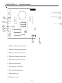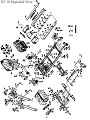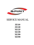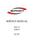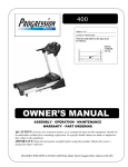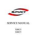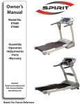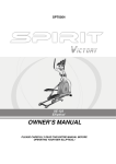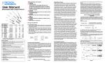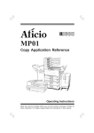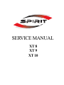
1
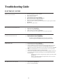
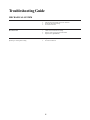
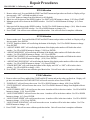
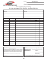
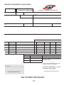
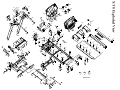
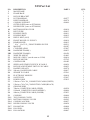
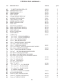
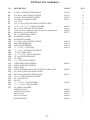
SERVICE MANUAL
XT 8
XT 9
XT 10
Table of Contents
Troubleshooting Guide
Electronic System……………………………………………….3
Mechanical System……………………………………………...4
Repair Procedures
Procedure 1 (Calibrating the unit)………………………………5
Procedure 2 (Checking wire harness)…………………………...6
Procedure 3 (Speed sensor adjustment)…………………………6
Procedure 4 (Checking treadmill circuit breaker)……………….6
Procedure 5 (Checking roller for magnet)……………………….6
Procedure 6 (Adjust torque boost)………………………………6
Procedure 7 (Replacing controller)……………………………...7
Procedure 8 (Replacing wire harness)…………………………...7
Procedure 9 (Replacing drive motor)……………………………7
Procedure 10 (Replacing incline motor)…………………………7
Procedure 11 (Controller diagram)………………………………8
Procedure 12 (XT 10 Engineering mode).……………………….9
Warranty
Contacting Customer Service…………………………………....10
Treadmill Warranty……………………………………………....10
Warranty Policy………………………………………………….11
Parts Order Form………………………………………………...12
Warranty Labor Credit Form…………………………………….13
XT 8
Exploded View...…………………………………………………14
Parts List....................................................................................15-17
XT 9
Exploded View....………………………………………………...18
Parts List......................................................................................19-21
XT 10
Exploded View....………………………………………………...22
Parts List......................................................................................23-25
2
Troubleshooting Guide
ELECTRONIC SYSTEM
No power
9.
Unit must be plugged into an outlet with power
Power switch must be illuminated
Tether cord must be in place
Check treadmill circuit breaker. (procedure 4)
Check “POWER” LED on controller. (procedure 11)
Make sure wires on board are plugged in securely.
Check wire harness for continuity. (procedure 2)
If LED’s on controller are not lit, test fuse on controller. If fuse is good, replace controller.
(procedure 7)
If LED’s are on, replace console.
LS error
Belt movement for a few seconds then LS error
1.
2.
3.
4.
5.
Run the calibration procedure. (procedure 1)
Adjust speed sensor. (procedure 3)
Check roller for magnet (Procedure 5)
Check wire harness for continuity. (procedure 2)
If roller has a magnet and sensor adjustment does not fix, replace speed sensor.
LS error
No belt movement at all then LS error
1.
2.
3.
Run the calibration procedure. (procedure 1)
Check wire harness for continuity. (procedure 2)
Look at LED labeled “PWM”. (procedure 11)
-If it lights up when the START button is pressed, replace the controller.
- If it does not light when the START button is pressed, replace the console.
There is no power to the console.
Incline does not work
1.
2.
3.
4.
5.
6.
7.
8.
1.
2.
3.
4.
5.
Belt surging
Belt speeds up and slows down frequently
1.
2.
3.
Run the calibration procedure. (procedure 1)
Check wire harness for continuity. (procedure 2)
If there is an ERR message in the incline window, make sure that all the wires from the
incline motor are connected to the controller correctly (procedure 12). If they are
connected correctly, and the calibration does not fix, replace the incline motor. (procedure
10)
When the UP and DOWN buttons are pressed, there should be a “beep” and a number
change in the incline window. If there isn’t, replace the console.
Observe the UP and DOWN diagnostic lights on the controller (procedure 11). When the
UP or DOWN buttons are pressed, you should (1) see one of the lights come on and (2)
hear a relay click.
If there is no relay click and no diagnostic lights, replace console and controller
(procedure 7).
If there is a relay click and a diagnostic light and motor wires are connected
correctly, replace incline motor.
Adjust torque boost (procedure 6)
Adjust speed sensor (procedure 3)
Replace controller (procedure 7)
3
Troubleshooting Guide
MECHANICAL SYSTEM
Belt noise
Drive motor noise
Deck noise
Squeaking or creaking while walking
1.
2.
3.
4.
Check belt to see if it needs to be tracked.
Take off motor hood to make sure noise is from belt.
Check belt and deck for damage.
Clean deck and re-lube.
1.
2.
3.
Check wires around motor for rubbing.
Remove, clean, and re-insert the motor brushes
Replace motor. (procedure 9)
1.
2.
Tighten deck bolts
Clean and re-lube deck
4
Repair Procedures
PROCEDURE 1: Calibrating the unit
XT8 Calibration
1. Remove tether cord. Press and hold the START and FAST buttons and put tether cord back on. Display will go
into test mode. “SET” will blink in middle of screen.
2. Use “STOP” button to change from Km (Meteric) to M (English).
3. Wheel size will be shown in the SPEED window. Use FAST or SLOW buttons to change. (2.50) Press START.
4. Minimum speed will be shown in the SPEED window. Use FAST or SLOW buttons to change. (0.5) Press
START.
5. Max speed will be shown in the SPEED window. Use FAST or SLOW buttons to change. (10.0) Max elevation
will be shown in the INCLINE window. Use UP or DOWN buttons to change. (14)
6. Press START. Unit will now auto-calibrate speed then incline. Unit will reset when it completes calibration.
XT9 Calibration
1. Remove tether cord. Press and hold the START and FAST buttons and put tether cord back on. Display will go
into test mode. Press ENTER.
2. “UNITS” English or Metric will scroll along the bottom of the display. Use UP or DOWN buttons to change.
Press ENTER.
3. “ADJUST WHEEL SIZE” will scroll along the bottom of the display and a number will flash in the calorie
window. Use UP or DOWN buttons to change. (2.30) Press ENTER.
4. “ADJUST MIN SPEED” will scroll along the bottom of the display and a number will flash in the calorie
window. Use UP or DOWN buttons to change. (0.5) Press ENTER.
5. “ADJUST MAX SPEED” will scroll along the bottom of the display and a number will flash in the calorie
window. Use UP or DOWN buttons to change. (10.0) Press ENTER.
6. “ADJUST MAX ELEVATION” will scroll along the bottom of the display and a number will be in the calorie
window. Use UP or DOWN buttons to change. (14) Press ENTER.
7. “GRADE RETURN” will scroll along the bottom of the display and “ON” or “OFF” will be in the calorie
window. Use UP or DOWN to change. (ON)
8. Press START. Unit will now auto-calibrate speed then incline. Unit will reset when it completes calibration.
XT10 Calibration
1. Remove tether cord. Press and hold the START and FAST buttons and put the tether cord back on. Display will
go into a test mode then FACTORY SETTING will scroll across the screen. Press ENTER.
2. “POWER ON” will scroll across the screen. Use UP or DOWN buttons to change. (ON) Press ENTER.
3. “UNITS ENGLISH” will scroll across the screen. Use UP or DOWN buttons to change from English to Metric.
Press ENTER.
4. “ADJUST WHEEL SIZE” will scroll across the screen. A number will be in the time window. Use UP or DOWN
buttons to change. (2.50) Press ENTER.
5. “ADJUST MIN SPEED” will scroll across the screen. A number will be in the time window. Use UP or DOWN
buttons to change. (0.5) Press ENTER.
6. “ADJUST MAX SPEED” will scroll across the screen. A number will be in the time window. Use UP or DOWN
buttons to change. (12.0) Press ENTER.
7. “ADJUST MAX ELEVATION” will scroll across the screen. A number will be in the time window. Use UP or
DOWN buttons to change. (15)
8. Press START. Unit will now auto-calibrate speed then incline. Unit will reset when it completes calibration.
5
PROCEDURE 2: Checking wire harness for continuity
2.1
2.2
2.3
2.4
2.5
Set your multimeter to read ohms.
Place the test leads at opposite ends of the wire, make sure both leads are on the same wire and are in contact
with metal.
If the reading is close to 0 ohms, the wire has continuity (unbroken).
If the reading is very high or there is no reading at all, there is no continuity.
If there is no continuity, the harness needs to be replaced.
PROCEDURE 3: Speed sensor adjustment
3.1
3.2
3.3
Take off the motor hood.
The speed sensor is located on the frame, near where the drive belt goes around the front roller.
The sensor should be adjusted to about 1/16th of an inch from the front roller.
PROCEDURE 4:
4:1
4.2
The circuit breaker is a small, red button between the power cord and the power switch.
Press the button in to reset.
PROCEDURE 5:
5.1
5.2
5.3
Check roller for magnet
The front roller should have a round magnet and a round counter weight.
Take a screw or something metallic and test each one.
Only one should be magnetic.
PROCEDURE 6:
6.1
6.2
6.3
6.4
Checking treadmill circuit breaker
Adjust Torque Boost
Using a small screw driver, turn the dial counter clockwise until it stops.
Press the START button on the console.
With someone standing on the walking belt, turn clockwise until the belt begins to move.
Increase the speed and check for smooth belt movement.
(See PROCEDURE 11 for location of Torque Boost)
6
PROCEDURE 7:
7.1
7.2
7.3
7.4
7.5
7.6
Disconnect power cord from unit.
Remove motor hood.
Remove two Phillips screws holding in the controller.
Disconnect all wires connected to the controller.
Insert new controller, secure with Phillips screws.
Reconnect wires to controller. (See Procedure 12 )
PROCEDURE 8:
8.1
8.2
8.3
8.4
8.5
Replacing drive motor
Turn power switch off.
Disconnect red and black motor wires from controller.
Loosen tension bolt and remove four motor bolts.
Take off drive belt.
Insert new motor into place.
Put drive belt on.
Put in four motor bolts. Do not tighten them all the way down.
Tighten the tension bolt until you only have about an inch of play in the drive belt.
Tighten down the four motor bolts.
Plug the motor wires into the controller.
PROCEDURE 10:
10.1
10.2
10.3
10.4
10.5
10.6
10.7
10.8
10.9
10.10
Replacing wire harness
Turn power switch off.
Unplug harness from console and controller.
Tie the end of the new harness to the old harness (with a zip-tie or spare wire).
As you pull the old harness out of the upright, you will pull the new harness in.
Connect to board and console, & turn power back on.
PROCEDURE 9:
9.1
9.2
9.3
9.4
9.5
9.6
9.7
9.8
9.9
9.10
Replacing controller
Replacing incline motor
Turn power switch off.
If possible, fold up unit.
Turn treadmill onto its side.
Disconnect motor wires from controller.
Remove bolt from incline tube.
Remove bolt from top of incline motor and take out motor.
Insert new motor and put in bolt on the top.
Reconnect motor wires to controller.
Turn on unit. The new motor should turn until it is at “zero”.
Insert bolt into incline tube.
7
PROCEDURE 11: Controller diagram
10
1
FUSE
2
9
AC 1
AC 2
8
3
4
5
DOWN
COM
UP
Down UP
6
7
1. Black wire from power switch
2. White wire from power switch
3. Black wire from incline motor
4. White wire from incline motor
5. Red wire from incline motor
6. Incline potentiometer
7. Wire harness connection
8. Torque boost adjustment
9. White motor wire
10. Red motor wire
8
PROCEDURE 12: XT 10 Engineering mode
1. Remove the tether cord.
2. Press and hold the START, ENTER, and STOP buttons and replaced the tether
cord.
3. The display will say ENGINEERING MODE. Press ENTER.
4. Press the UP and DOWN buttons to scroll through the following sub menus:
-Calibration
-Factory Settings
-Security
-Functions
-Display Test
-Key Test
5. Press ENTER to access the desired program.
-Calibration
Speed Calibration – In this mode, you can test the speed.
Incline Calibration – In this mode, you can test the incline.
-Factory Settings
This mode will allow you to view the Wheel size, Max inc, Max and Min speed.
Use the UP and DOWN buttons to scroll through. (They cannot be changed here)
-Security
Child Lock On/Off
Press ENTER to turn on or off. To unlock display, press START and ENTER.
-Functions
Sleep Mode On/Off. Press ENTER to turn on or off.
Units English/Metric. Press ENTER to change.
Maintenance
Lube Message Reset. Press ENTER to reset.
Odometer Reset. Press ENTER to reset.
Pause Mode On/Off. Press ENTER to turn on or off.
-Display Test
Test all LED’s
-Key Test
Test all buttons on console.
9
CONTACTING CUSTOMER SERVICE
It is the responsibility of the Dealer to assemble and setup any Spirit product they have sold, as
well as diagnose problems and perform service, regardless of the product’s location. Recognizing
the importance of insuring the consumer’s satisfaction, Spirit technical support will always be
available to assist the Dealer in diagnosing a problem. All warranties are valid from the original
date of purchase by the original purchaser.
PARTS ORDERS
Fax 870-930-9013
Fax your order using a completed parts purchase order to (870) 930-9013. Please do not call to
place your parts orders, fax only. Service technicians are available to assist in the repair of
treadmills. If taking parts orders by telephone, technical service calls will go unanswered.
Standard shipping is UPS ground. If you need an order shipped by another method, you must
pay for shipping.
CUSTOMER SERVICE
Call 800-258-4555
Calling from Store Location
Dial 1 to reach the first available technician, or select the extension number for one technician. You
must have the serial number of the machine.
Eddie Greene, Customer Service Supervisor ext. 630
Jerry Savage, Customer Support ext. 632
Travis Lawrence, Customer Support ext. 633
Kevin Thomas, Customer Support ext. 628
If the technician you choose is unavailable, leave a detailed message. Leave only one message. Do
not call another extension. Do not leave multiple messages. This results in a duplication of effort
and keeps our technicians from assisting you and other customers in a prompt manner.
Calling from Customer Location
Dial 0 for an operator. Relay to the operator you are a dealer and in a customer’s home. You will
be assisted by the first available technician.
TREADMILL WARRANTY
Spirit Manufacturing Inc. warrants all its treadmills’ parts for a period of 5 years from the date of
retail sale, as determined by sale receipt, or eighteen (18) months from the original factory shipping
date, whichever comes first. Spirit’s responsibilities include providing new or remanufactured
parts, at Spirit’s option, and technical support to our independent dealers and servicing
organizations. In the absence of a dealer or service organization, these warranties will be
administered by Spirit directly to a consumer. An extended warranty period applies to the
following components:
XT 8
Frame - Lifetime
Motor - 20 years
All parts - 3 years
Labor - 1 year
XT 9 & XT 10
Frame - Lifetime
Motor - 30 years
All parts - 3 years
Labor - 1 year
10
WARRANTY POLICY
Parts Returns
It is very important that you have not only the model number but also the serial number on hand when placing a parts order. If
a serial number is provided at the time a warranty parts order is placed the required parts will be sent to you at no charge. If the
unit is no longer covered under warranty the parts will be billed to you on 30 day payment terms.
If a warranty replacement part is required to be returned to Spirit it will be noted on the packing list included in your shipment.
Also noted on the packing list will be the amount you will be invoiced if the parts are not returned within 30 days.
Parts Required to be Returned for Credit
Upper and Lower Electronics - All STS / SC / SL / Inspire / Z / XT Series
Paperwork Requirement: A copy of your invoice or packing list and diagnostic form (if included with replacement part)
must be returned with the defective part to receive warranty consideration.
Warranty Labor Reimbursement Procedure
Complete Request for Warranty Labor Credit Form.
Fax completed form to Terry Jordan at (870) 930-9013.
Once Spirit has received your returned parts, your request will be processed and returned by fax to you.
What is Not Covered
1)
2)
3)
4)
5)
6)
7)
8)
Failures created due to improper installation or maintenance.
Repairs requiring only simple adjustments, fuses, or calibrations.
Damages sustained from shipping - Freight claim must be filed with your carrier.
Repairs that are made beyond the warranty period.
Repairs where the customer is paying the base labor fee to the dealer.
Units that are dealer stock or floor models.
Trips for diagnostic visit.
Residential units in a commercial setting.
Credit will not be issued for repairs in which:
1) Parts required for return are not returned to Spirit within 30 days.
2) All paperwork is not completed or returned.
3) Spirit confirms that work was not completed.
Warranty Labor Reimbursement Policy
Spirit has established a set of guidelines that are fair to both independent service companies and to Spirit. Our policy on labor
warranty reimbursement is simple...we pay a one time flat completion fee of $80 per service occurrence. Once all work required
to complete the repair has been finished and all parts required for return have been returned to Spirit either credit or payment in
the amount of $80 will be issued to your company. The one-time flat completion fee of $80 will be paid only when the repair is
complete and the unit has been returned to proper working condition. If your company needs consideration for labor or trip fees
that are higher than Spirit’s standard fees, they will be evaluated on a case-by-case basis. (e.g. - travel to perform service work
in Manhattan). Any change in the fee schedule must be approved in writing by Spirit before any work is performed.
For Dealers That Wish To Use Third Party Service
It is Spirit’s policy that all dealers service products that they sell to end users. If your company chooses to use an independent
company for service, you are responsible for all service work. Our labor reimbursement policies apply in every case and any
charges in excess of Spirit’s one time flat completion fee will be billed back to the selling dealer. In certain circumstances, we
will work directly with an independent service company, but we will not pay for any service that deviates from our policy for
dealers wishing to have this arrangement. Dealers will be responsible to the service company for all charges disallowed by
Spirit. Any deviation from Spirit policy must be approved in advance in writing.
11
Fax to:
870-930-9013
Attention:
PARTS PURCHASE ORDER
Fill in completely for processing.
All orders are shipped F.O.B. Spirit Mfg., Jonesboro, Arkansas.
Dealer Name
Account No.
Ship to
Street & No.
Street & No.
City
State
Phone Number
Fax Number
Purchase Order No. Dealer Buyer’s Name
Qty.
Zip
City
State
Phone Number
Fax Number
All parts ordered are considered stock orders unless a serial number is listed below each
parts’ description box. A serial number listed will qualify it for warranty evaluation.
Part No.
Description
Unit Price
Zip
Date of Order
Amount
Order Completion - Orders must be signed!
Shipping Instructions: (All orders will be shipped via ground delivery
If a part is not accompanied by a serial number, it will be assumed that the
unless otherwise indicated.) Buyer will be responsible for all expe-
part order is for stock. We encourage all dealers to stock parts. Spirit will
dited shipping charges.
always be fair to all dealers on credit for parts. Spirit reserves the right to
Special Instructions:
subject parts returns to a 20% restocking fee if Spirit determines that the
2nd Day Air________________
Next Day Air_______________
dealer has excessively ordered parts randomly to repair a problem.
Saturday Delivery___________
Buyer Signature_____________________________ Date____________
Initial Your Special Shipping Instructions Here______________________
(Orders for expedited shipping without initials will be shipped via ground delivery.)
12
REQUEST FOR WARRANTY LABOR CREDIT
Labor Warranty :
Date of Repair
Spirit is responsible
Customer is responsible
Model#
Service Company
P.O. BOX 2037 JONESBORO, ARKANSAS 72402
Serial Number
Svc CoAcct Number
Owner’s Name
Owner’s Address
Selling Dealer
Number
Selling Dlr Acct
Phone Number With Area Code
Date Sold
Problem
Repair Done
FACTORY USE ONLY
QUANTITY
PART NUMBER
PART DESCRIPTION
WTY
TEST RESULTS
UNIT PRICE
WORK ORDER
INVOICE
FACTORY USE ONLY
FREIGHT:
SHIPPING:
LABOR
TRIP
WARRANTY CREDIT WILL BE ISSUED TO
DEALER ACCOUNT.
____________
TOTAL LABOR
ALL PARTS MUST BE RETURNED TO FACTORY
UNLESS INSTRUCTED OTHERWISE.
____________
Authorization No.___________________________
CLAIMS MUST BE RETURNED TO SPIRIT
CORP. WITHIN 7 DAYS OF REPAIR.
____________
_________________________________________
SHADED AREAS FACTORY USE ONLY
WARRANTY ADMINISTRATOR
FAX TO SPIRIT (870) 930-9013
13
XT 8 Exploded View
39-9
26
39-8
101
27-127-136 25
39-9
39-9
39-7
39-8
102
39-7
27
36
6
37
100
94
25
91
39-4
20R
90
91
22
5
90 90
96
90
72
87
85
88
66
76
18
66
87
87
32
22
14
87
87
87
87
87
89
35 47
92
21
87
65
86 86
60
60
47
52
33
74
75
79 74
99
75
74
52
52
34
84
38
1
84
86
74
84
52
86
84
92
52
87
121
113
116
77
3
75
73
87
16
79
73
54
57
53R
53L
79
87
54
57
87
97
98
86
51
84
122
126
120
86
84
86
59
950914PM1450
86
12
13
51
86
104
84
86
21
74
75
86
84
52
89
105
90
48
74
46
28 87
58
2
49
23
69
87
87
87 38
29
46
87
85
8947
10
87
87
92
21
87
50
76
82
83
81
83
81
90
90
24 64
42
37
86
82
14
4
30
39-1
39-5
27
20L
96
78
15
42
94
102
90
87
85
91
89
94
95
94
91
89
94
95
94
26
102 102
39-2
XT8 Part List
NO.
1
2
3
4
5
6
7
8
10
11
12
13
14
15
16
17
18
19
20L
20R
21
22
23
24
25
26
27
27~1
28
29
30
32
33
34
35
36
37
38
39
39~1
39~2
39~4
39~5
39~7
39~8
39~9
DESCRIPTION
MAIN FRAME
FRAME BASE
INCLINE BRACKET
LEFT HANDRAIL
RIGHT HANDRAIL
CONSOLE SUPPORT
OUTER SLIDE (same as XT200/600)
INNER SLIDE (same as XT200/600)
BOTTOM MOTOR COVER
BELT GUIDE
RUNNING DECK
RUNNING BELT
DRIVE BELT (610J)
FRONT ROLLER W/ PULLEY
REAR ROLLER
˜ 10 x ˜ 14 x 35.5L_ FRONT WHEEL SLEEVE
MAGNET
CYLINDER (450N)
HANDGRIP FOAM(L)
HANDGRIP FOAM(R)
WIRE TIE MOUNT
MOTOR-2.5HP YC (not the same as U-F80)
INCLINE MOTOR
CONTROLLER
SPEED ADJUSTMENT SWITCH W/CABLE
INCLINE ADJUSTMENT SWITCH W/CABLE
HANDPULSE ASSY.
900 m/m_HANDPULSE CABLE
SENSOR W/CABLE
ELECTRONIC MODULE
SAFETY KEY
POWER CORD
150m/m x 764 x 764_CONNECTING CABLE(WHITE)
150m/m x 764 x 764_CONNECTING CABLE(BLACK)
GROUND WIRE
700m/m_COMPUTER CABLE (UPPER)
1100m/m_COMPUTER CABLE (MIDDLE)
900m/m_COMPUTER CABLE (LOWER)
CONSOLE
TOP CONSOLE COVER
BOTTOM CONSOLE COVER
CONSOLE ANCHOR
INNER CONSOLE COVER
FAN MOTOR
FAN GRILL
FAN ANCHOR
15
PART #
000377
000378
000409
000410
000413
000411
000412
022553
000414
000415
000311
000507
023097
000433
000434
010083
000416
022762
000405
000424
000425
000370
000417
022561
000418
022497
022812
QTY.
1
1
1
1
1
1
1
1
1
2
1
1
1
1
1
2
2
1
1
1
5
1
1
1
1
1
2
2
1
1
1
1
1
1
1
000520
000406
022823
000404
000419
000385
000427
000428
000808
000420
000807
1
1
1
1
1
1
2
1
2
2
4
XT8 Part List continued....
NO.
DESCRIPTION
PART #
QTY.
42
43R
43L
44
45
46
47
48
49
50
51
52
53L
53R
54
57
58
59
60
61
62
63
64
65
66
67
69
70
71
72
73
74
75
76
77
78
79
80
81
82
83
84
85
86
87
88
˜ 38_BUTTON HEAD END CAP
FRAME BASE CAP (R)
FRAME BASE CAP (L)
FRONT WHEEL
REAR WHEEL
%30x60_SQUARE END CAP
MOTOR COVER ANCHOR
LEFT MOTOR COVER
MIDDLE MOTOR COVER
RIGHT MOTOR COVER
FOOT RAIL
M6xØ25x22_CUSHION
REAR ADJUSTMENT BASE (L)
REAR ADJUSTMENT BASE (R)
FOOT PAD CAP
Ø30x3/8"_FOOT PAD
SENSOR RACK
LUBRICANT
˜ 10 x 24 x 3T _NYLON WASHER (A)
˜ 50 x 13 x 3T _NYLON WASHER (B)
1/2" x 1-1/4"_CARRIAGE BOLT
1/2" x 1"_HEX HEAD SCREW
3/8" x 4"_SOCKET HEAD CAP SCREW
3/8" x92m/m_HEX HEAD SCREW
3/8" x 1" _HEX HEAD SCREW
5/16"×2-3/4"(JSYr)__BUTTON HEAD SOCKET SCREW
M8 x 12m/m _HEX HEAD SCREW
3/8" x 2"_FLAT HEAD SOCKET SCREW
5/16" x 1" __BUTTON HEAD SOCKET SCREW
M8 x 60m/m _HEX HEAD SCREW
M8 x 80m/m _SOCKET HEAD CAP SCREW
M6 x 25m/m _FLAT HEAD COUNTERSINK SCREW
1/2" x 8T_ NYLON NUT
3/8" x 7T_ NYLON NUT
5/16" x 6T_ NYLON NUT
M8 x 8T_ NYLON NUT
3/8" x 7T_ NUT
˜ 35 x 5/16" x 1.5T _ FLAT WASHER
˜ 25 x 10 x 1.5T _ FLAT WASHER
˜ 19 x 10 x 1.5T _ FLAT WASHER
˜ 10 _SPRING WASHER
˜ 6.5 x 25 x 1T_CONCAVE WASHER
M5_RAISED WASHER
4x12m/m_SELF TAPPING SCREW
5x16m/m_TAPPING SCREW (Black)
5x19m/m_TAPPING SCREW
022024
000389
000388
022479
000127
022480
22484
000390
000421
000392
000422
000423
000394
000395
000396
022713
022989
022271
2
1
1
2
2
2
3
1
1
1
2
8
1
1
2
2
1
1
2
4
2
2
1
1
4
2
2
2
2
1
2
8
4
4
3
1
3
2
4
4
4
8
3
18
28
2
16
000061
000058
022885
023102
000080
010108
010099
023010
000070
010110
030057
XT8 Part List continued....
NO.
DESCRIPTION
PART #
QTY.
89
90
91
92
93
94
95
96
97
98
99
100
101
102
104
105
106
107
108
109
110
111
112
113
114
115
116
119
120
121
122
123
124
126
127
5x16m/m_TAPPING SCREW (Black)
3.5x12m/m_SELF TAPPING SCREW
4x38m/m_SELF TAPPING SCREW
3.5x16m/m_TAPPING SCREW
5/16"_NUT
5/16" x 15m/m_BUTTON HEAD SOCKET SCREW
˜ 5/16" x 19 x 1.5T _CURVED WASHER
M5 x 15m/m_PHILLIPS HEAD SCREW
010110
010113
000325
022979
5
21
4
5
2
14
4
4
1
1
1
1
1
8
1
1
1
1
1
2
2
1
1
1
1
1
1
1
1
1
1
1
1
1
1
1
1
2
1
1
COMB. M5 ALLEN WRENCH & PHILLIPS HEAD SCREW DRIVER
M6(66X86)_ALLEN WRENCH
3/8"×2"_HEX HEAD SCREW
HANDGRIP FOAM(L)
HANDGRIP FOAM(R)
3.5×32m/m_SELF TAPPING SCREW
NON-SLIP RUBBER(L)
NON-SLIP RUBBER(R)
˜ 5ט 8×25L_ CLEVIS PIN
˜ 5ט 8×9L_ FASTENING BUSHING
˜ 8×30L_LINK SHAFT
˜ 8ט 12.7×12L_ SHAFT BUSHING
2T_ FASTENING BRACKET
2T_LINK
˜ 1.0_ DUAL ROTA-SPRING
CHENCHING ROTA-SPRING
STEEL ROPE ROTA-SPRING
STEEL ROPE
CLENCHING HANDLE ASSY-LOCKING CABLE ASSY.
M3×10m/m_PHILLIPS HEAD SCREW
M5×15m/m_PHILLIPS HEAD SCREW
5/16"×2"_PHILLIPS HEAD SCREW
M5_ NYLON NUT
M3_NUT
˜ 5ט 10×1.0T_ FLAT WASHER
˜ 5ט 12×1.0T_ FLAT WASHER
M3_SPRING WASHER
OVERLAY (LCD)
OVERLAY (8 Button)
DECAL (Side)
DECAL (Console)
HARDWARE KIT
17
000087
000913
000089
022973
000914
000313
000314
030101
000082
000429
000913
023086
000399
000400
000435
000402
000430
XT 9 Exploded View
18
XT9 Part List
No.
DESCRIPTION
PART #
1
2
3
4
5
6
7
8
10
11
12
13
14
15
16
17
18
19
20L
20R
21
22
23
24
25
26
27
27~1
28
29
30
32
33
34
36
37
38
39
39~1
39~2
39~4
39~5
39~7
39~8
39~9
42
MAIN FRAME
FRAME BASE
INCLINE BRACKET
LEFT HANDRAIL
RIGHT HANDRAIL
CONSOLE SUPPORT
OUTER SLIDE
INNER SLIDE
BOTTOM MOTOR COVER
BELT GUIDE
RUNNING DECK
RUNNING BELT
DRIVE BELT - 610J
FRONT ROLLER W/ PULLEY
REAR ROLLER
˜ 10 x ˜ 14 x 35.5L_ FRONT WHEEL SLEEVE
MAGNET
CYLINDER - 570N
HANDGRIP FOAM(L)
HANDGRIP FOAM(R)
WIRE TIE MOUNT
MOTOR-2.5HP YC (not the same as U-F80)
INCLINE MOTOR
CONTROLLER
SPEED ADJUSTMENT SWITCH W/CABLE
INCLINE ADJUSTMENT SWITCH W/CABLE
HANDPULSE ASSY.
900 m/m_HANDPULSE CABLE
SENSOR W/CABLE
ELECTRONIC MODULE
SAFETY KEY
POWER CORD
150m/m x 764 x 764_CONNECTING CABLE(WHITE)
150m/m x 764 x 764_CONNECTING CABLE(BLACK)
800m/m_COMPUTER CABLE (UPPER)
1100m/m_COMPUTER CABLE (MIDDLE)
1000m/m_COMPUTER CABLE (LOWER)
CONSOLE
TOP CONSOLE COVER
BOTTOM CONSOLE COVER
CONSOLE ANCHOR
INNER CONSOLE COVER
FAN MOTOR
FAN GRILL
FAN ANCHOR
˜ 38_BUTTON HEAD END CAP
19
000377
000378
000379
000380
000413
000381
000382
022553
000436
000437
000311
000507
023098
000433
000434
010083
000416
022762
000405
000424
000425
000370
000417
022561
000418
022497
022812
022720
000406
000407
000383
000384
000385
000386
000387
000808
000420
000807
022024
Q’ty
1
1
1
1
1
1
1
1
1
2
1
1
1
1
1
2
2
1
1
1
6
1
1
1
1
1
2
2
1
1
1
1
1
1
1
1
1
1
1
1
2
1
2
2
4
2
XT9 Part List continued....
No.
DESCRIPTION
PART #
Q’ty
43R
43L
44
45
46
47
48
49
50
51
52
53L
53R
54
57
58
59
60
61
62
63
64
65
66
67
70
71
72
73
74
75
76
77
78
79
80
81
82
83
84
85
86
87
88
89
90
91
FRAME BASE CAP (R)
FRAME BASE CAP (L)
FRONT WHEEL
REAR WHEEL
%30x60_SQUARE END CAP
MOTOR COVER ANCHOR
LEFT MOTOR COVER
MIDDLE MOTOR COVER
RIGHT MOTOR COVER
FOOT RAIL
M8xØ30x35_CUSHION
REAR ADJUSTMENT BASE (L)
REAR ADJUSTMENT BASE (R)
FOOT PAD CAP
Ø30x3/8"_FOOT PAD
SENSOR RACK
LUBRICANT
˜ 10 x 24 x 3T _NYLON WASHER (A)
˜ 50 x 13 x 3T _NYLON WASHER (B)
1/2" x 1-1/4"_CARRIAGE BOLT
1/2" x 1"_HEX HEAD SCREW
3/8" x 4"(JSYr)_SOCKET HEAD CAP SCREW
3/8" x92m/m(JSYr)_HEX HEAD SCREW
3/8" x 1" _HEX HEAD SCREW
5/16"×2-3/4"_BUTTON HEAD SOCKET SCREW
3/8" x 2"_FLAT HEAD SOCKET SCREW
5/16" x 1" _BUTTON HEAD SOCKET SCREW
M8 x 60m/m _HEX HEAD SCREW
M8 x 80m/m _SOCKET HEAD CAP SCREW
M8 x 25m/m _FLAT HEAD COUNTERSINK SCREW
1/2" x 8T_ NYLOC NUT
3/8" x 7T_ NYLOC NUT
5/16" x 6T_ NYLOC NUT
M8 x 8T_ NYLOC NUT
3/8" x 7T_NUT
˜ 35 x 5/16" x 1.5T _ FLAT WASHER
˜ 25 x 10 x 1.5T _ FLAT WASHER
˜ 19 x 10 x 1.5T _ FLAT WASHER
˜ 10 _SPRING WASHER
˜ 6.5 x 25 x 1T _CONCAVE WASHER
M5_RAISED WASHER
4x12m/m_SELF TAPPING SCREW
5x16m/m_TAPPING SCREW (BLACK)
5x19m/m_TAPPING SCREW
5x16m/m_TAPPING SCREW (BLACK)
3.5x12m/m_SELF TAPPING SCREW
4x38m/m_SELF TAPPING SCREW
000389
000388
022479
000127
022480
022484
000390
000391
000392
000393
022482
000394
000395
000396
022713
022989
022271
1
1
2
2
2
3
1
1
1
2
6
1
1
2
2
1
1
2
4
2
2
1
1
4
2
2
2
1
2
8
4
4
3
1
3
2
4
4
4
8
3
18
28
2
5
21
4
20
000061
022885
000101
023102
000080
000080
010099
023010
000070
010110
030057
010110
010113
000325
XT9 Part List continued....
No.
DESCRIPTION
PART #
Q’ty
92
93
94
95
96
97
98
99
100
101
102
104
105
106
107
108
109
110
111
112
113
114
115
116
119
120
121
122
123
124
126
127
3.5x16m/m_TAPPING SCREW
˜ 32 x 1.8T _NUT
5/16" x 15m/m _BUTTON HEAD SOCKET SCREW
˜ 5/16" x 19 x 1.5T _CURVED WASHER
M5 x 15m/m_PHILLIPS HEAD SCREW
022979
6
2
14
4
6
1
1
1
1
1
8
1
1
1
1
1
2
2
1
1
1
1
1
1
1
1
1
1
1
2
1
1
1
1
1
2
1
M5 ALLEN WRENCH / PHILLIPS HEAD SCREW DRIVER
M6(66X86)_ALLEN WRENCH
3/8"×2"_HEX HEAD SCREW
HANDGRIP FOAM(L)
HANDGRIP FOAM(R)
3.5×32m/m_SELF TAPPING SCREW
NON-SLIP RUBBER(L)
NON-SLIP RUBBER(R)
˜ 5ט 8×25L_ CLEVIS PIN
˜ 5ט 8×9L_ FASTENING BUSHING
˜ 8×30L_LINK SHAFT
˜ 8ט 12.7×12L_ SHAFT BUSHING
2T_ FASTENING BRACKET
2T_LINK
˜ 1.0_ DUAL ROTA-SPRING
CHENCHING ROTA-SPRING
STEEL ROPE ROTA-SPRING
STEEL ROPE
CLENCHING HANDLE ASSY. w/ Cable
M3×10m/m_PHILLIPS HEAD SCREW
M5×20m/m_PHILLIPS HEAD SCREW
5/16"×2"_PHILLIPS HEAD SCREW
M5_ NYLOC NUT
M3_NUT
˜ 5ט 10×1.0T_ FLAT WASHER
˜ 5ט 12×1.0T_ FLAT WASHER
M3_SPRING WASHER
HARDWARE KIT
OVERLAY (LCD)
OVERLAY (KEYPAD)
DECAL (SIDE)
DECAL (CONSOLE)
000087
000913
000089
022973
000914
000313
000314
030101
000082
000563
023086
000398
000431
000400
000401
000402
21
XT 10 Exploded View
22
XT10 Part List
No.
DESCRIPTION
PART #
1
2
3
4
5
6
7
8
10
11
12
13
14
15
16
17
18
19
20L
20R
21
22
23
24
25
26
27
27~1
28
29
30
32
33
34
36
37
38
39
39~1
39~2
39~4
39~5
39~7
39~8
39~9
42
43R
MAIN FRAME
FRAME BASE
INCLINE BRACKET
LEFT HANDRAIL
RIGHT HANDRAIL
CONSOLE SUPPORT
OUTER SLIDE
INNER SLIDE
BOTTOM MOTOR COVER
BELT GUIDE
RUNNING DECK
RUNNING BELT
DRIVE BELT - 610J
FRONT ROLLER W/ PULLEY
REAR ROLLER
˜ 10 x ˜ 14 x 35.5L_ FRONT WHEEL SLEEVE
MAGNET
CYLINDER - 570N
HANDGRIP FOAM(L)
HANDGRIP FOAM(R)
WIRE TIE MOUNT
MOTOR, 2.75hp YC
INCLINE MOTOR
CONTROLLER
SPEED ADJUSTMENT SWITCH W/CABLE
INCLINE ADJUSTMENT SWITCH W/CABLE
HANDPULSE ASSY.
900 m/m_HANDPULSE CABLE
SENSOR W/CABLE
ELECTRONIC MODULE
SAFETY KEY
POWER CORD
150m/m x 764 x 764_CONNECTING CABLE(WHITE)
150m/m x 764 x 764_CONNECTING CABLE(BLACK)
800m/m_COMPUTER CABLE (UPPER)
1100m/m_COMPUTER CABLE (MIDDLE)
1000m/m_COMPUTER CABLE (LOWER)
CONSOLE
TOP CONSOLE COVER
BOTTOM CONSOLE COVER
CONSOLE ANCHOR
INNER CONSOLE COVER
FAN MOTOR
FAN GRILL
FAN ANCHOR
˜ 38_BUTTON HEAD END CAP
FRAME BASE CAP (R)
23
000377
000378
000379
000380
000413
000381
000382
022553
000436
000437
000311
000507
023098
000433
000434
010083
000432
022762
000405
000424
000425
000370
000417
022561
000418
022497
022812
022720
000406
000407
000397
000384
000385
000386
000387
000808
000420
000807
022024
000389
Q’ty
1
1
1
1
1
1
1
1
1
2
1
1
1
1
1
2
2
1
1
1
6
1
1
1
1
1
2
2
1
1
1
1
1
1
1
1
1
1
1
1
2
1
2
2
4
2
1
XT10 Part List continued....
No.
DESCRIPTION
PART #
43L
44
45
46
47
48
49
50
51
52
53L
53R
54
57
58
59
60
61
62
63
64
65
66
67
70
71
72
73
74
75
76
77
78
79
80
81
82
83
84
85
86
87
88
89
90
91
92
FRAME BASE CAP (L)
FRONT WHEEL
REAR WHEEL
%30x60_SQUARE END CAP
MOTOR COVER ANCHOR
LEFT MOTOR COVER
MIDDLE MOTOR COVER
RIGHT MOTOR COVER
FOOT RAIL
M8xØ30x35_CUSHION
REAR ADJUSTMENT BASE (L)
REAR ADJUSTMENT BASE (R)
FOOT PAD CAP
Ø30x3/8"_FOOT PAD
SENSOR RACK
LUBRICANT
˜ 10 x 24 x 3T _NYLON WASHER (A)
˜ 50 x 13 x 3T _NYLON WASHER (B)
1/2" x 1-1/4"_CARRIAGE BOLT
1/2" x 1"_HEX HEAD SCREW
3/8" x 4"(JSYr)_SOCKET HEAD CAP SCREW
3/8" x92m/m(JSYr)_HEX HEAD SCREW
3/8" x 1" _HEX HEAD SCREW
5/16"×2-3/4"(JSYr)_BUTTON HEAD SOCKET SCREW
3/8" x 2"_FLAT HEAD SOCKET SCREW
5/16" x 1" _BUTTON HEAD SOCKET SCREW
M8 x 60m/m _HEX HEAD SCREW
M8 x 80m/m _SOCKET HEAD CAP SCREW
M8 x 25m/m _FLAT HEAD COUNTERSINK SCREW
1/2" x 8T_ NYLOC NUT
3/8" x 7T_ NYLOC NUT
5/16" x 6T_ NYLOC NUT
M8 x 8T_ NYLOC NUT
3/8" x 7T_NUT
˜ 35 x 5/16" x 1.5T _ FLAT WASHER
˜ 25 x 10 x 1.5T _ FLAT WASHER
˜ 19 x 10 x 1.5T _ FLAT WASHER
˜ 10 _SPRING WASHER
˜ 6.5 x 25 x 1T _CONCAVE WASHER
M5_RAISED WASHER
4x12m/m_SELF TAPPING SCREW
5x16m/m_TAPPING SCREW (Black)
5x19m/m_TAPPING SCREW
5x16m/m_TAPPING SCREW (Black)
3.5x12m/m_SELF TAPPING SCREW
4x38m/m_SELF TAPPING SCREW
3.5x16m/m_TAPPING SCREW
000388
022479
000127
022480
022484
000390
000391
000392
000393
022482
000394
000395
000396
022713
022989
022271
24
000061
022885
000101
023102
000080
010099
023010
000070
010110
030057
010110
010113
000325
022979
Q’ty
1
2
2
2
3
1
1
1
2
6
1
1
2
2
1
1
2
4
2
2
1
1
4
2
2
2
1
2
8
4
4
3
1
3
2
4
4
4
8
3
18
28
2
5
21
4
6
XT10 Part List continued....
No.
DESCRIPTION
PART #
93
94
95
96
97
98
99
100
101
102
104
105
106
107
108
109
110
111
112
113
114
115
116
119
120
121
122
123
124
126
127
˜ 32 x 1.8T _NUT
5/16" x 15m/m _BUTTON HEAD SOCKET SCREW
˜ 5/16" x 19 x 1.5T _CURVED WASHER
M5 x 15m/m_PHILLIPS HEAD SCREW
M5 ALLEN WRENCH / PHILLIPS HEAD SCREW DRIVER
M6(66X86)_ALLEN WRENCH
3/8"×2"_HEX HEAD SCREW
HANDGRIP FOAM(L)
HANDGRIP FOAM(R)
3.5×32m/m_SELF TAPPING SCREW
NON-SLIP RUBBER(L)
NON-SLIP RUBBER(R)
˜ 5ט 8×25L_ CLEVIS PIN
˜ 5ט 8×9L_ FASTENING BUSHING
˜ 8×30L_LINK SHAFT
˜ 8ט 12.7×12L_ SHAFT BUSHING
2T_ FASTENING BRACKET
2T_LINK
˜ 1.0_ DUAL ROTA-SPRING
CHENCHING ROTA-SPRING
STEEL ROPE ROTA-SPRING
STEEL ROPE
CLENCHING HANDLE ASSY. w/ Cable
M3×10m/m_PHILLIPS HEAD SCREW
M5×20m/m_PHILLIPS HEAD SCREW
5/16"×2"_PHILLIPS HEAD SCREW
M5_ NYLOC NUT
M3_NUT
˜ 5ט 10×1.0T_ FLAT WASHER
˜ 5ט 12×1.0T_ FLAT WASHER
M3_SPRING WASHER
HARDWARE KIT
OVERLAY (LED)
OVERLAY (KEYPAD)
DECAL (SIDE)
DECAL (CONSOLE)
25
000087
000913
000089
022973
000914
000313
000314
030101
000082
000563
023086
000398
000445
000400
000403
000402
Q’ty
2
14
4
6
1
1
1
1
1
8
1
1
1
1
1
2
2
1
1
1
1
1
1
1
1
1
1
1
2
1
1
1
1
1
2
1