1
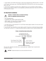
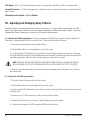
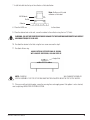
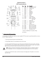
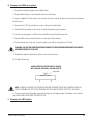
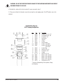
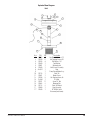
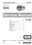
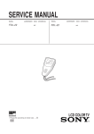
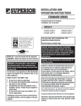
Multi-Pattern Lake Management Aerator
Service Manual
Instant Fountain Contents
Water Feature Placement . . . . . . . . . . . . . . . . . . . . . . . . . . . . . . . . . . . . . . . . . . . . . . . . . . 2
Installation . . . . . . . . . . . . . . . . . . . . . . . . . . . . . . . . . . . . . . . . . . . . . . . . . . . . . . . . . . . 2-7
Technical Specifications . . . . . . . . . . . . . . . . . . . . . . . . . . . . . . . . . . . . . . . . . . . . . . . . . 7-8
Adjusting/Changing Spray Patterns and Accompanying Exploded View Diagrams . . . . . . . 8-13
Light Kit Installation. . . . . . . . . . . . . . . . . . . . . . . . . . . . . . . . . . . . . . . . . . . . . . . . . . . 14-15
Trouble Shooting Guide . . . . . . . . . . . . . . . . . . . . . . . . . . . . . . . . . . . . . . . . . . . . . . . . 16-17
Maintenance. . . . . . . . . . . . . . . . . . . . . . . . . . . . . . . . . . . . . . . . . . . . . . . . . . . . . . . . . . . 18
Winterization. . . . . . . . . . . . . . . . . . . . . . . . . . . . . . . . . . . . . . . . . . . . . . . . . . . . . . . . . . . 18
Exploded View Diagram - Unit . . . . . . . . . . . . . . . . . . . . . . . . . . . . . . . . . . . . . . . . . . . . . . 19
Customer Satisfaction Policy . . . . . . . . . . . . . . . . . . . . . . . . . . . . . . . . . . . . . . . . . . . . . . . 20
Aerator Startup Report . . . . . . . . . . . . . . . . . . . . . . . . . . . . . . . . . . . . . . . . . . . . . . . . . . . 21
Rain Bird ® LMM Service Manual
1
I. Water Feature Placement
When using your Water Feature for aesthetic enhancement only, position the Water Feature in the place you feel it is best
suited. When using your Water Feature for water aeration choose the LM11 pattern and place the Water Feature as shown
below.
II. Unit Installation
A. Unpack and inspect your Water Feature. Remove the protective cardboard ring around the top of the unit. Report any
shipping damage to the carrier who delivered your Rain Bird® Water Feature. Verify you have received the following:
1. Water Feature - you will find a label located on the inner motor houing. This label can be read through the screen.
Check to make sure you have received the correct horsepower and voltage.
The Water Feature comes standard with 100 ft (30m) of power cable. If a custom length was specified, verify you
have received the proper length.
2. Power Control Center - A mini power control center is standard on all 60Hz Water Features. If your unit is 60Hz,
verify the control center is present. On 50Hz units, the panel is optional. If ordered, verify the panel is of the proper
voltage and frequency.
3. Hardware Kit - included in this kit are 2 mooring/anchor clips, a LM10 spray nozzle, 2 cable ties and one 1/8"
Allen wrench.
4. Optional Light Kit - If lights were ordered, verify the proper number of lights and a light power control center are
enclosed.
B. Prior to installation, please measure your water depth. All Rain Bird® Water Features require at least 18" or .5m of water to run properly. If the water is too shallow, dig out a portion of the pond bottom directly under the Water Feature. If high
waves or large fluctuations in depth occur, it will be necessary to allow for more than the required 18"
or .5m.
2
Rain Bird ® LMM Service Manual
C. Pattern Selection: your Rain Bird® Water Feature has been factory configured with the LM20 spray pattern. If the LM10
or LM11 pattern is desired, refer to the “ADJUSTING/CHANGING SPRAY PATTERN SECTION” of this manual and change the
pattern at this time.
D. Light Kit: lights are optional on your Water Feature. If ordered with your unit, they should be in stalled on the Water
Feature at this time. Electrical installation must be completed by a qualified licensed electrician. Refer to the LIGHT INSTALLATION section of this manual.
III. Electrical Installation
WARNING: TO PREVENT FATAL OR SERIOUS ELECTRICAL
SHOCK, THIS EQUIPMENT MUST BE INSTALLED:
•
•
•
•
By a licensed electrician
In compliance with national and local electrical codes
With the proper size fusing and/or circuit breaker protection
With 5 milliamp ground fault protection (GFCI)
A. Your Water Feature is safety tested and ETL, ETLc and CE listed. However, proper installation is the most crucial step to
assure a safe and reliable unit.
B. Install Rain Bird® Power Control Panel as close to pond as possible. The enclosure is rated for both indoor and outdoor
use. Mount panel a minimum of 3' (1m) above the ground and above any flood zone. Always keep the panel door closed.
TYPICAL 115V CONTROL PANEL INSTALLATION
115V Waterproof GFIC Outlet
Protected by 15A Circuit Breaker
Water Feature
Lite Transformer
Control Panel
Panels Mounted 3 Feet (1 Meter)
Above the Ground and Flood Zone
Cable in Conduit for
Protection and as Required
to Meet Electrical Codes
Verify your power cable does not exceed maximum recommended length. If additional length is required, contact
Rain Bird® for a solution.
CAUTION: The power control panel must not be accessible from the water.
Rain Bird ® LMM Service Manual
3
Maximum Cable Length
Horsepower
Voltage
Frequency (Hz)
1/2
1/2
1/2
3/4
115
230
220
230
60
60
50
60
Maximum Length
#12 Cable
125' or 37.8m
480' or 146.3m
700' or 213.4m
350' or 106.7m
C. Have a licensed, qualified electrician install the proper size fusing and/or circuit breaker protection as listed below. All
work must be done in compliance with national and local electrical codes.
NOTE: THE 230V panel includes the proper fusing.
Horsepower
Voltage
Frequency (Hz)
1/2
1/2
1/2
3/4
115
230
220
230
60
60
50
60
Circuit Breaker Slo-Blow/Delay
Size
Fuse Size
30
20
15
10
15
10
20
15
D. Have the electrician connect the power control center to the power source.
NOTE: For 115V units, a plug is supplied with the panel. This plug must be attached to the Water Feature cable and installed only into the power control panel
WARNING: Never run the Water Feature out of the water. Running the unit out of the water may damage the
motor and void warranty
CAUTION: KEEP HANDS CLEAR OF THE IMPELLER WHEN TRYING TO START THE
WATER FEATURE.
E. Physically disconnect the power cable from its source and proceed with the installation of the unit.
DANGER
THERMALLY PROTECTED AUTOMATIC RESET
•UNIT WILL RESTART WITHOUT WARNING AFTER PROTECTOR TRIPS.
•KEEP FINGERS OUT OF IMPELLER SYSTEM UNTIL UNIT IS DISCONNECTED.
•ALWAYS DISCONNECT UNIT FROM POWER SOURCE BEFORE SERVICING.
NOTE: This unit contains thermal protection to help prevent intense heat conditions in the motor that could damage the
motor. If your unit is intermittently starting and stopping, the unit is showing symptoms of a larger problem and you should
disconnect power from the unit and call your local service center.
4
Rain Bird ® LMM Service Manual
IV. Physical Installation
NOTE: Your Rain Bird® Water Feature may either be moored or anchored in the water. Mooring is the preferred method as it
provides an easy method to retrieve the unit and allows for fluctuations in water height.
WARNING: DO NOT USE THE POWER CABLE AS A MOORING LINE.
A. The hardware kit supplied with your unit includes 2 mooring clips. These clips are designed to slide into any of the 6
slots in the bottom of the float cover.
B. Install two mooring clips on opposite sides of the unit. Fasten the clips from the inside so that the holes are on the
outside. Refer to figure below.
Figure A
C. Using cable tie supplied, secure power cord to one of the cable tie mounts on the bottom of the unit.
D. Mooring the Water Feature
1. The following is required to moor your Rain Bird® Water Feature.
a. 1/4" or 6.3mm polypropylene rope or 1/8" stainless steel cable for use as mooring lines. Note: Use all brass
or stainless steel hardware.
b. For mooring points, either wooden stakes, 1/2" or 125mm rebar, or “duckbill” type earth anchors.
-Duckbill Earth Anchors are driven into the ground, using a drive rod and heavy hammer, compacting the earth as they drive downward, until they reach the recommended depth.
After removing drive rod, installer pulls up on cable. This planes or rotates the anchor into load lock
position, like a toggle bolt in undisturbed earth.
2. Choose a suitable location for your water feature. Refer to the “WATER FEATURE PLACEMENT” section of this
manual.
3. Secure your first mooring point. If you are using a stake or rebar, make sure to pound the mooring point securely
into the ground on outer edge of the pond. If you are mooring with an earth anchor, you will need to place the earth
anchor two feet into the pond, below the surface of the water, and then pound the earth anchor two feet into the pond
bottom. The earth anchor will allow your mooring lines to be virtually unnoticeable as it will be hidden beneath the
water surface.
Rain Bird ® LMM Service Manual
5
4. Attach the mooring lines to the mooring clips on the Water Feature.
5. Carefully, place the Water Feature into the water.
6. Walk one mooring line around to the far edge of the pond and pull the Water Feature into the desired location.
7. Secure your second mooring point. Attach the line/cable leaving enough slack in the lines to allow the Water
Feature to turn 120 degrees or 1/3 turn. This slack will allow for proper start-up, wave action, and fluctuations in the
water level.
8. Proceed to FINAL ELECTRICAL INSTALLATION instructions in this manual.
E. Anchoring the Water Feature.
1. The following is required to anchor your Rain Bird® Water Feature.
a. 1/4" or 6.3mm polypropylene rope or 1/8" stainless steel cable for use as anchor lines. Note: use all brass or
stainless steel hardware.
b. Two 15 lb or 8 kg anchors.
2. Choose a suitable location for your Water Feature. Refer to the “WATER FEATURE PLACEMENT” section of this
manual.
3. Using a boat, take the Water Feature and anchors to the chosen location.
4. Drop the anchors (with anchor lines attached) out of the boat at a minimum of a 45 degree angle from the desired
location of the Water Feature. See figure on previous page.
5. Bring the anchor lines together and secure each of them to the corresponding anchor clip on the Water Feature.
Attach the line/cable leaving enough slack in the lines to allow the Water
Feature to turn 120 degrees or 1/3 turn. This slack will allow for proper startup, wave action, and fluctuations in the
water level.
6
Rain Bird ® LMM Service Manual
V. Final Electrical Installation
CAUTION: All electrical work must be done by a qualified, licensed electrician.
A. With the Water Feature securely moored or anchored, re-attach the power cable to the source of electricity.
NOTE: Rain Bird® suggests that the power cable be encased in conduit when placed underground. The Water Feature’s
underwater power cable should be encased in conduit from the power source to approximately 3-4' or 1m out into the
water. The insures against possible cable damage.
B. Apply power to the unit. With the unit running, have the licensed electrician conduct a voltage and amperage reading. Verify your unit is receiving the proper voltage. Record the voltage and amperage readings on the back cover of this
manual.
Unit Voltage
115 VOLTS 60HZ
220/240 VOLTS 50HZ
230 VOLTS 60HZ
MIN. VOLTAGE
109
209
218
MAX. VOLTAGE
122
242
242
C. Test the GFCI device for proper operation by depressing the test button. GFCI devices must be tested monthly or per
manufacturers recommendations.
D. This completes the installation of your Water Feature. If desired, the spray pattern can be adjusted or changed. Refer to
the ADJUSTING/CHANGING SPRAY PATTERN section of this manual.
VI. Technical Specifications
HP
Voltage
and
Phase
Motor
RPM
Running
Amp
Draw
Resistance
Ohms
Spray
Height*
Spray
Diameter*
Pumping
Rate
50
1/2
75
3/4
115 1 ph.
230 1 ph.
220 1 ph
230 1 ph.
3450 @ 60Hz
3450 @ 60Hz
2875 @ 50Hz
3450 @ 60Hz
12.0
6.0
3.9
8.0
1.0-1.3
4.2-5.2
6.3-7.7
3.0-3.6
2.5'
2.5'
0.8m
3.0'
12'
12'
4.3m
19'
125 gpm
125 gpm
24m3/hr
135 gpm
Model
LM11
LM20
50
1/2
75
3/4
115 1 ph.
230 1 ph.
220 1 ph
230 1 ph.
3450 @ 60Hz
3450 @ 60Hz
2875 @ 50Hz
3450 @ 60Hz
12.0
6.0
3.9
8.0
1.0-1.3
4.2-5.2
6.3-7.7
3.0-3.6
115 1 ph.
230 1 ph.
220 1 ph
230 1 ph.
3450 @ 60Hz
3450 @ 60Hz
2875 @ 50Hz
3450 @ 60Hz
12.0
6.0
3.9
8.0
1.0-1.3
4.2-5.2
6.3-7.7
3.0-3.6
Inside
Outside
Inside
Outside
8'
8'
2.1m
10'
4'
4'
1.2m
6'
2'
2'
0.6m
2'
12'
12'
3.7m
16'
80 gpm
80 gpm
18m3/hr
90 gpm
LM10
50
1/2
75
3/4
12'
12'
2.9m
15'
2'
2'
0.6m
2'
80 gpm
80 gpm
18m3/hr
90 gpm
*Spray patterns will vary by adjusting the diffuser ring. Therefore, the figures given are averages. Spray patterns will also vary due to voltage drop, humidity and other relevant site situations
Rain Bird ® LMM Service Manual
7
Unit Weight: 45 lbs. or 21K and includes power center, unit, spray patterns and 100' or 30.48m of underwater cable.
Induced Circulation: is 10 times the pumping rate. Induced circulation is the mixing effect which is occurring below the
water's surface.
Minimum Operating Depth: is 18" or 500mm.
VII. Adjusting and Changing Spray Patterns
Your Water Feature can be configured into three different spray patterns. It has been factory assembled with the LM20
pattern. To change or adjust the pattern, refer to the proper section below and follow the directions carefully. Refer to the
Exploded View Diagrams following each section for an illustration of referenced parts.
A. Adjusting the LM20 spray pattern. The outer spray pattern of the LM20 can be adjusted, using the supplied 1/8"
Allen wrench, by repositioning the diffuser on top of the unit. Follow the steps below for adjustment.
1. Physically disconnect the power from the Water Feature.
2. Bring the Water Feature to shore and place the unit on a flat surface.
3. Using the supplied 1/8" Allen wrench, loosen the two setscrews holding the diffuser ring in position. Adjusting
the ring up will lower the height of the outer pattern and increase its width. Lowering the ring will make the outer pattern higher and narrower. Adjust the ring to the new location and secure the two setscrews.
NOTE: CAREFULLY, SECURE THE SETSCREWS. APPLYING EXCESSIVE FORCE WILL DAMAGE THE RING OR
NOZZLE ASSEMBLY. THE TOP OF THE RING MUST NOT BE AD JUSTED ABOVE THE TOP OF THE NOZZLE.
4. Place your unit back into the water, secure the mooring lines and reapply power. If the pattern is not as desired,
repeat above steps.
B. Changing to the LM20 spray pattern.
1. Physically disconnect the power from the Water Feature.
2. Bring the Water Feature to shore and place the unit on a flat surface.
3. Using the supplied 1/8" Allen wrench, loosen the two setscrews securing the diffuser ring in position and remove
the diffuser ring.
4. Remove the four 1/4" bolts and the four screws on the top of the top retainer.
5. Carefully lift the top retainer off of the unit. A slight twisting motion may be required.
6. If the unit was configured as a LM10, remove the LM10 nozzle from the unit.
8
Rain Bird ® LMM Service Manual
7. Install the baffle into the top of the collector as illustrated below.
LM20 Nozzle
Baffle
Note: Baffle must fit inside
collector as illustrated
Collector
8. Place the LM20 nozzle (nozzle with 8 holes in center area) into the retainer.
9. Place the retainer back on the unit, secure the retainer to the collector using the four 1/4" bolts.
WARNING: DO NOT USE EXCESSIVE FORCE. DAMAGE TO THE PUMPING COMPONENTS MAY RESULT.
MAXIMUM TORQUE IS 20 IN-LBS.
10. Re-attach the retainer to the float using the four screws removed in step 4.
11. Re-attach diffuser ring.
ALWAYS ATTACH DIFFUSER RING AS SHOWN,
WITH ANGLED SIDE DOWN, HOLLOW SIDE UP.
Angled Side
NOTE: CAREFULLY, SECURE THE SETSCREWS. APPLYING EXCESSIVE FORCE WILL DAMAGE THE RING OR
NOZZLE ASSEMBLY. THE TOP OF THE RING MUST NOT BE ADJUSTED ABOVE THE TOP OF THE NOZZLE.
12. Place your unit back into the water, secure the mooring lines and reapply power. If the pattern is not as desired,
refer to adjusting LM20 SPRAY PATTERN SECTION.
Rain Bird ® LMM Service Manual
9
Exploded View Diagram
LM20 Pumping Configuration
2
1
3
4
5
6
7
1
8
3
9
11
10
12
13
14
15
16
19
17
18
Item
1
2
3
4
5
6
7
8
9
10
11
12A
12B
P/N
FR103
FR109
FR105
FR108
FR804
FR209
FR803
FR805
FR207
FR701
FR206
FR800
FR801
Qty
8
11
8
2
1
1
1
1
1
2
1
*
*
13
14
15
16
17
18A
18B
18C
18D
19
FR205
FR102
FR104
FR204
C2-112
FR601
FR602
FR603
FR604
FR114
1
4
4
1
4
*
*
*
*
4
Description
Hex Bolt, 1/4"-20 x 2.75"
Self Tapping Screw, #10
Flat Washer, 1/4"
Set Screw
Diffuser
Top Retainer
LM20 Nozzle
LM20 Baffle
Collector
O-Ring
Pump Chamber
Impeller, 1/2HP 60Hz
Impeller, 3/4HP 60Hz or
1/2HP 50Hz
Impeller Ring
Lock Nut, 5/16"-24
Flat Washer, 5/16"
Standoff
Lock Nut, 1/4"-20
Motor, 1/2HP 115V 60Hz
Motor, 1/2HP 230V 60Hz
Motor, 1/2HP 220V 50Hz
Motor, 3/4HP 230V 60Hz
Heavy Washer, 5/16"
* One per unit depending on horsepower, voltage,
and frequency
C. Adjusting the LM10 spray pattern.
The spray pattern of the LM10 can be adjusted, using the suppplied 1/8" Allen wrench, by repositioning the diffuser on top of
the unit. Follow the steps below:
1. Physically disconnect the power from the Water Feature.
2. Bring the Water Feature to shore and place the unit on a flat surface.
3. Using the supplied 1/8" Allen wrench, loosen the two setscrews holding the diffuser ring in position. Adjusting
the ring up will increase the spray pattern width and slightly lower it’s height. Lowering the ring will make the pattern
higher and narrower. Adjust the ring to the new location and secure the two setscrews.
NOTE: CAREFULLY, SECURE THE SETSCREWS. APPLYING EXCESSIVE FORCE WILL DAMAGE THE RING OR
NOZZLE ASSEMBLY. THE TOP OF THE RING MUST NOT BE ADJUSTED ABOVE THE TOP OF THE NOZZLE
4. Place your unit back into the water, secure the mooring lines and reapply power. If the pattern is not as desired,
repeat above steps.
10
Rain Bird ® LMM Service Manual
D. Changing to the LM10 spray pattern.
1. Physically disconnect the power from the Water Feature.
2. Bring the Water Feature to shore and place the unit on a flat surface.
3. Using the supplied 1/8" Allen wrench, loosen the two setscrews securing the diffuser ring in position and remove
the diffuser ring.
4. Remove the four 1/4" bolts and the four screws on the top of the top retainer.
5. Carefully lift the top retainer off of the unit. A slight twisting motion may be required.
6. If the unit was configured as a LM20, remove the LM20 nozzle and baffle from the unit.
7. Place the LM10 nozzle (nozzle without holes in center area) into the retainer.
8. Place the retainer back on the unit, secure the retainer to the collector using the four 1/4" bolts.
WARNING: DO NOT USE EXCESSIVE FORCE. DAMAGE TO THE PUMPING COMPONENTS MAY RESULT.
MAXIMUM TORQUE IS 20 IN-LBS.
9. Re-attach the retainer to the float using the 4 screws removed in step 4.
10. Re-attach diffuser ring.
ALWAYS ATTACH DIFFUSER RING AS SHOWN,
WITH ANGLED SIDE DOWN, HOLLOW SIDE UP.
Angled Side
NOTE: CAREFULLY, SECURE THE SETSCREWS. APPLYING EXCESSIVE FORCE WILL DAMAGE THE RING OR
NOZZLE ASSEMBLY. THE TOP OF THE RING MUST NOT BE ADJUSTED ABOVE THE TOP OF THE NOZZLE.
11. Place your unit back into the water, secure the mooring lines and reapply power. If the pattern is not as desired,
refer to ADJUSTING LM10 SPRAY PATTERN SECTION.
E. Changing to the LM11 pattern.
Rain Bird ® LMM Service Manual
11
Exploded View Diagram
LM10 Pumping Configuration
2
1
3
4
5
6
7
1
3
9
11
10
12
13
14
15
16
19
17
18
Item
1
2
3
4
5
6
7
9
10
11
12A
12B
P/N
FR103
FR109
FR105
FR108
FR804
FR209
FR802
FR207
FR701
FR206
FR800
FR801
13
14
15
16
17
18A
18B
18C
18D
19
FR205
FR102
FR104
FR204
C2-112
FR601
FR602
FR603
FR604
FR114
Qty
8
11
8
2
1
1
1
1
1
2
1
*
*
1
4
4
1
4
*
*
*
*
4
Description
Hex Bolt, 1/4"-20 x 2.75"
Self Tapping Screw, #10
Flat Washer, 1/4"
Set Screw
Diffuser
Top Retainer
LM10 Nozzle
Collector
O-Ring
Pump Chamber
Impeller, 1/2HP 60Hz
Impeller, 3/4HP 60Hz or
1/2HP 50Hz
Impeller Ring
Lock Nut, 5/16"-24
Flat Washer, 5/16"
Standoff
Lock Nut, 1/4"-20
Motor, 1/2HP 115V 60Hz
Motor, 1/2HP 230V 60Hz
Motor, 1/2HP 220V 50Hz
Motor, 3/4HP 230V 60Hz
Heavy Washer, 5/16"
* One per unit depending on horsepower, voltage,
and frequency
NOTE: The shape of the LM11 pattern can not be adjusted.
1. Physically disconnect the power from the Water Feature.
2. Bring the Water Feature to shore and place the unit on a flat surface.
3. Using the supplied 1/8" Allen wrench, loosen the two setscrews securing the diffuser ring in position and remove
the diffuser ring.
4. Remove the four 1/4" bolts and the four screws on the top of the top retainer.
5. Carefully lift the top retainer off of the unit. A slight twisting motion may be required.
6. Remove the nozzle from the unit. If the unit was configured as a LM20, also remove the LM20 baffle.
7. Place the retainer back on the unit, secure the retainer to the collector using the four 1/4" bolts.
12
Rain Bird ® LMM Service Manual
WARNING: DO NOT USE EXCESSIVE FORCE. DAMAGE TO THE PUMPING COMPONENTS MAY RESULT.
MAXIMUM TORQUE IS 20 IN-LBS.
8. Re-attach the retainer to the float using the (4) screws removed in step 4.
9. Place your unit back into the water, secure the mooring lines and reapply power. The LM11 pattern can not be
adjusted.
Exploded View Diagram
LM11 Pumping Configuration
2
1
3
6
1
3
9
11
10
12
14
13
15
16
17
19
18
Item
1
2
3
6
9
10
11
12A
12B
P/N
FR103
FR109
FR105
FR209
FR207
FR701
FR206
FR800
FR801
Qty
8
11
8
1
1
2
1
*
*
13
14
15
16
17
18A
18B
18C
18D
19
FR205
FR102
FR104
FR204
C2-112
FR601
FR602
FR603
FR604
FR114
1
4
4
1
4
*
*
*
*
4
Description
Hex Bolt, 1/4"-20 x 2.75"
Self Tapping Screw, #10
Flat Washer, 1/4"
Top Retainer
Collector
O-Ring
Pump Chamber
Impeller, 1/2HP 60Hz
Impeller, 3/4HP 60Hz or
1/2HP 50Hz
Impeller Ring
Lock Nut, 5/16"-24
Flat Washer, 5/16"
Standoff
Lock Nut, 1/4"-20
Motor, 1/2HP 115V 60Hz
Motor, 1/2HP 230V 60Hz
Motor, 1/2HP 220V 50Hz
Motor, 3/4HP 230V 60Hz
Heavy Washer, 5/16"
* One per unit depending on horsepower, voltage,
and frequency
Rain Bird ® LMM Service Manual
13
VIII. Light Installation
CAUTION: All electrical work must be done by a qualified licensed electrician.
A. Mounting the lights to your Water Feature.
1. Lights are mounted on the side of the float shell using one of the six screws securing the two halves together.
2. To mount the lights, remove two or three of the screws as shown. If two lights are being installed, it is recommended for them to be placed 180 degrees apart, three lights 120 degrees apart.
3. Install the L-bracket as shown.
4. Install the light fixture to the L-bracket using the 5/16" nut supplied.
5. The light fixture can be tilted or rotated slightly for the best effect by loosening the #10 screw and nut.
NOTE: The main light cord must be secured to the bottom of the unit using the cable tie supplied. Failure
to do so may result in a tilted spray pattern. Do not attach light and pump cables together at the base of the
unit!! This may result in a tilted spray pattern.
6. Loosely attach the cable tie supplied to the main light cord (approximately 3 feet from the first light).
7. Insert the cable tie into the cable tie mount in the bottom of the unit. Tighten cable tie securely and cut off excess.
14
Rain Bird ® LMM Service Manual
Exploded View Diagram
Light Set Configuration
2
5
8
9
1
11
13
15
16
Item
P/N
Qty
1
GP1002
1
2
24-0006 6*
4
4
GP5200 1*
6
5
GP5800 1*
6A
GP5102 1*
7
6B GP5102B
10
6C GP5102R
12
6D GP5102G
20
19
6E GP5102Y
18
7
GP8300 1*
14
8
GP8400 3*
22 21
9
GP5700 3*
10 GP3001A 1*
17
11
GP1211 6*
12
GP5801 1*
13
GP5004 **
14
GP1215 ***
15
GP3999 ****
16
GP1300
2
17A F-GP56
17B F-GP46-P
18
GP1208 1*
19 C2-1142 1*
20
GP1200 1*
21
FR704
1*
22
GP1207 1*
Description
Transformer/Timer
Light Ring Screw
Wire Rock Guard
Light Ring
Clear Lens
Blue Lens
Red Lens
Green Lens
Yellow Lens
Light O-Ring
Bulb Retaining Screw
Bulb Clip
Bulb, 14W
Light Ring Nut
Plastic Light Housing
Light Cable Connector
End Plug
Cable, 12/3 (Order per Foot)
Fork Connector (2 per Cable End)
56" Jumper (1 per 2 Light Set)
46" Jumper (2 per 3 Light Set)
Locknut, 5/16"-18
Light "U" Bracket
Light "U" Bracket Screw
Light "L" Bracket
Locknut , #10-24
* Quantity per Light
** 2 per First or Middle Light, 1 per Last Light
*** 1 per Last Light ONLY
**** 100ft is Standard, length may be custom
Rain Bird ® LMM Service Manual
15
IX. Trouble Shooting Guide
SYMPTOM
Motor will not start
POSSIBLE CAUSE
Breaker/fuse has tripped
CORRECTION
Check breaker or fuse. Reset/replace
Low voltage
Verify voltage in spec
Excessive cable length
Verify acceptable maximum cable length
Defective or disconnected
power cable
Check & verify cable is properly connected
GFCI device has tripped
Reset and test GFCI device. Replace if
necessary
Defective power cable
Inspect cable for torn insulation
Bad or noisy power
Low voltage or surges may cause
nuisance tripping
Unit turns on and off
Low voltage
Verify voltage is within spec
Fuse blows or circuit
breaker trips
Excessive cable length
Verify acceptable
maximum cable length
Defective motor
Take a winding resistance reading
GFCI device trips
continuously
1/2HP 115V 60Hz = 1.0-1.3 ohms
1/2HP 220V 50Hz = 6.3-7.7 ohms
1/2HP 230V 60Hz = 4.2-5.2 ohms
3/4HP 230V 60Hz = 3.0-3.6 ohms
Spray pattern low
or distorted
16
Clogged screen
Clean screen
Clogged nozzle or
pumping chamber
Clean nozzle or pumping chamber of debris
LM20 model, baffle
is missing
Insert baffle in unit
LM10 or LM11
model, baffle is present
Remove baffle
Rain Bird ® LMM Service Manual
SYMPTOM
POSSIBLE CAUSE
Unit hitting bottom
CORRECTION
Move unit to deeper water
Diffuser ring installed wrong
Install diffuser ring with
angled side down into unit.
LM10/LM20
Spray pattern is
straight up, low,
and heavy
Missing diffuser ring
Attach diffuser ring
LM20 model
no inner spray pattern
LM10 nozzle installed
Install LM20
nozzle (8 holes in
center of nozzle)
Spray pattern tilted
Cables not attached to
bottom of unit
Attach cable using
cable tie
Rain Bird ® LMM Service Manual
17
X. Maintenance
Your Rain Bird® Water Feature has been designed for years of dependable service.
• The screen should be cleaned as required to prevent any intake restrictions.
• At least once a year, you should thoroughly inspect the water feature, underwater cable, and mooring/anchor lines
for any signs of external damage.
Winterization
If the temperature in your region of the country falls below 30 degrees for any extended period of time, Rain Bird® strongly
suggests that you remove your Water Feature from the water and store it in a dry and above freezing temperature location.
Storage in a shed or garage where temperatures drop below freezing is not recommended as unit may freeze.
!! WARNING !!
This unit is not made to run in winter weather conditions. Leaving your Rain Bird® Water
Feature operating during the winter can lead to the Water Feature freezing in. If your Water
Feature freezes in, motor or pumping component damage can occur. This will not be covered under warranty.
The motor used in this Water Feature is of a water lubricated design. Therefore, the unit
must not be allowed to freeze as this will cause damage to the motor and pumping components. Unit must be stored in above freezing temperatures!
18
Rain Bird ® LMM Service Manual
Exploded View Diagram
Unit
1
4
6
2
3
5
2
17
8
9
10
11
12
13
6
14
15
Item
P/N
Qty
1
FR103
8
2
FR109 11
3
FR105
8
4
FR209
1
5
FR901
1
6
FR200
1
8 42-0011 1
9
1
10
FR113
1
11
FR301
1
12
FR106
5
13 C2-930
1
14
FR101 11
15
FR302
2
16
FR112
2
17
FR500
1
17* FR549
1
Rain Bird ® LMM Service Manual
16
Description
Hex Bolt, 1/4"-20 x 2.75"
Self Tapping Screw, #10
Flat Washer, 1/4"
Top Retainer
Warning Label
Shell/Screen Assembly
Float
Pump Chmbr/Motor Assy
Cable Tie
Motor Sleeve
Self Tapping Screw, #8
ID Label
Speed "U" Nut
Mooring Clip
Cable Tie Mount
Cord Assembly
OPTIONAL Quick
Disconnect(not shown)
19
Rain Bird® Professional Customer Satisfaction Policy
WARRANTY: Rain Bird will repair or replace at no charge any Rain Bird professional product that fails in normal use within the warranty period stated below. You must return it to the dealer or distributor where you bought it. This commitment to repair or replace
is our sole and total warranty.
Implied warranties of merchantability and fitness, if applicable, are limited to one year from the date of sale.
We will not, under any circumstances, be liable for incidental or consequential damages, no matter how they occur.
a) TURF PRODUCTS
c) AGRICULTURAL PRODUCTS
Falcon Series rotors, the T-Bird‚_Series rotors, the R-50
Series rotors, 5000 Series rotors, 1800 Series pop-up spray
heads, U-Series nozzles, brass MPR nozzles, A-8S and
PA-8S-PRS shrub adapters and 1300 and 1400 bubblers
- 5 years.
PC Dripline - 3 years
Lake Management Aerator:
LM10, LM11, LM20, LM30 - 5 years.
All agricultural products - 2 years
Lake Management Aerator: LMM - 2 years
d) ALL OTHER PRODUCTS - one year
Rain Guns - 3 years (in agricultural applications only)
Disk Fillers - 1 year
Pressure Gauges - 1 year
Lake Management Aerator Lights - 1 year
All other turf products - 3 years.
ADDENDUM: In freezing climates, it is necessary to properly
prepare the installed system in winter shutdown in order to
minimize the potential for freeze damage.
b) GOLF PRODUCTS
Golf Rotors: TG-25, DR, DH, DS, ESR and EAGLE™ series
Golf rotors - 3 years.
Additionally, any TG-25, DR, DH, DS or EAGLE rotor sold and
installed in conjunction with a Rain Bird swing joint - 5 years.
Proof of concurrent installation is required
Swing Joints - 5 years.
Brass and Plastic Valves: EFB and PE-B Remote Control
Valves, and Brass Quick Coupling Valves and Keys - 3 years.
Filtration system controllers - 3 years.
Rain Bird cannot and does not warranty against damage to
equipment caused by lightning or electrical surges.
PRICE CHANGES: Prices are subject to change without
notice.
DESIGN CHANGES: Rain Bird Sprinkler Mfg. Corp. reserves
the right to redesign, alter or modify its products without
incurring any liability from anyone’s inventory of such parts
or products that may become obsolete
Lake Management Aerator: LM10, LM11, LM20, LM30 - 5
years
Lake Management Aerator: LMM - 2 Years
Lake Management Aerator Lights - 1 year
All other golf products - 1 year
For price and availability of service parts, please call:
OTTERBINE BAREBO, INC.
(610) 965-6018
(800) 237-8837
20
Rain Bird ® LMM Service Manual
AERATOR STARTUP REPORT
CUSTOMER:
ADDRESS:
DISTRIBUTOR:
ADDRESS:
PHONE #:
PHONE #:
PRODUCT INFORMATION:
MODEL OF AERATOR:
HP:
VOLTAGE:
OPTIONS (CIRCLE INSTALLED):
SERIAL NUMBER OF UNIT:
SITE INFORMATION:
WATER DEPTH AT AERATOR:
POWER
TRANSFORMER:
PHASE CONVERTER:
PHASE:
(FT)
YES
NO
TYPE:
YES
NO
TYPE:
SURFACE
BUCK
SCREEN
ROCKCOVER
LIGHTS
SEQUENCER
ACERAGE:
BOOST
(ACRES)
SIZE:
SIZE:
BASIC CONDITION OF WATER:
INSTALLATION INFORMATION:
ANCHORING
METHOD:
MOORING
ANCHORS
DISTANCE BETWEEN ANCHORS:
(FT)
CABLE LENGTH & SIZE (FROM SOURCE TO CONTROL PANEL):
CABLE LENGTH & SIZE (FROM CONTROL PANEL TO AERATOR):
SUPPLY VOLTAGE PRIOR TO STARTUP:
(L1-L2)
(L1-L3)
(L2-L3)
VOLTAGE WITH AERATOR ON:
(L1-L2)
(L1-L3)
(L2-L3)
AMPERAGE (2 MINUTE RUN TIME):
L1
L2
L3
AMPERAGE (45 MINUTE RUN TIME):
L1
L2
L3
NOTES:
Rain Bird Corporation • 6991 E. Southpoint Rd. • Tucson, AZ 85706 • 520-741-6100 FAX 520-741-6522
Rain Bird Corporation
Contractor, Landscape Drip
and Accessories Division
970 W. Sierra Madre
Azusa, CA 91702
Phone: (626) 812-3400
Fax: (626) 812-3411
Rain Bird Corporation
Commercial Division
6991 East Southpoint Road
Tucson, AZ 85706
Phone: (520) 741-6100
Fax: (520) 741-6146
Rain Bird International, Inc.
145 North Grand Avenue
Glendora, CA 91741
Phone: (626) 963-9311
Fax: (626) 963-4287
Rain Bird Technical Service
(800) 247-3782
(U.S. and Canada only)
The Intelligent Use of Water.™—Visit www.rainbird.com
to learn more about our efforts.
® Registered Trademark of Rain Bird Corporation
© 2004 Rain Bird Corporation 4/04
DXXXXX