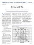
1
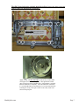
SERVICE MANUAL
Designed by a Quilter, for Quilters.®
5/12/09
© 2009 Handi Quilter, Inc.
Table of Contents
About the HQ Fusion (I)
About the Manual (I)
Service Manual General Rules (I)
General Specifications (II)
Assembly Torque Specifications (III)
Lubrication Specifications (IV)
Adjustments:
Section
Lubrication Instructions………………………………………………..……………….0
General Observation of Front Frame Cover, Mast and Hand Wheel ………….............1
Removal of Front Cover ……………………………………………………………….2
Securing Flats and Screws……………………………………………..……………….3
Axial Play Check and Adjustment..…………………………………………………….4
Adjusting the Base Plate ……………………………………………………………….5
Adjusting the Motor Drive / Timing Belt Tension……………….…………………….6
Adjusting the Presser Bar Height / Presser Foot………………………………………..7
Needle Position, Check, & Adjustment…………………………………………...........8
Adjustment of the Loop Lift and Needle Distance…..…………………………………9
Adjusting Needle Height………………………………………………………………10
Adjustment of the Stop Finger …………………………………………………..…….11
1
About the HQ Fusion Quilting Machine
The HQ Fusion™ utilizes high-tech electronics and an innovative touch-pad user
interface to offer greater functionality and ease of operation to home quilters than ever
before conceived in the quilting industry. The HQ Fusion™ quilting machine is a high
quality machine that incorporates very robust design features and is very easy to service.
The HQ Fusion™ machine is constructed following a specific sequence of operations similar to the construction of a house. Walls cannot be erected until the foundation is in
place. Similarly, this service manual has been written with an adjustment logic that is
driven by the construction processes used to create the machine. If the service technician
carefully follows the adjustment steps in the order presented, a fine running sewing
machine is possible each and every time.
About the Manual
The purpose of this service manual is to help the technician complete a repair on a
machine accurately and quickly. The manual is complete with photographs and
explanations that we hope will aid you in your repair efforts. In addition to the teaching
aids found herein, you will also find all of the tools listed that are necessary for
adjustments. If you need help in locating these tools for purchase, please contact Handi
Quilter.
Handi Quilter’s Customer Service technical staff is available for assistance and advice
during normal business hours. For additional help in technical training, we refer you to
the training schedule at the Corporate Office in North Salt Lake, Utah.
Service Manual General Rules
•
Adjustments shown in the manual should only be made if a setting deviates from the
tolerance specified in the manual.
•
Adjustments should be made only in the logical sequence shown and described in the
manual. (Do not jump ahead or start in the middle of the adjustment sequence – this
may cause additional or more serious problems than the original issue.)
•
Safety must be considered when working on any machine. Safety warnings are
included throughout this manual where appropriate, but these warnings do not address
all possible safety concerns that might confront the service technician.
•
When working on or near any live electrical assemblies, the power cable must be
removed from the machine.
•
We urge you to observe the cautions in the manual.
•
Please note that the hand wheel must always be turned in the direction of normal
rotation unless otherwise instructed. This is especially true when making the loop lift
timing and needle height adjustment. (Exceptions are removing thread locks or
testing belt tension – the handwheel may be rocked forward and reverse in these
cases)
2
HandiQuilter.com
Page 3
General Specifications
Sewing Opening Dimensions:
Sewing Speed:
Needle System:
Needle Sizes, (recommended):
Hook System:
Bobbin Type:
Bobbin Case:
Motor Type:
Needle Positioning:
Electrical Power:
LED Power Consumption:
Sew Foot Stroke/Lift:
Needle Bar Stroke:
Take-Up Stroke:
Lubrication, (main components):
Lubrication of hook:
Page 4
(245mm X 610mm)
9.625” X 24”
Manual Mode:
Min 110spm, Max 2200spm
Regulated Mode:
Min 0spm, Max full speed
134 (135 X 7)
12/80 - 20/125
(Rotary, custom made, Cerliani,
Type FA, Vertical, M Bobbin)
Aluminum, Class M
Cerliani, Type MF
Brushless DC, internal encoding
Up/down, half stitch, walking stitch
90 – 264 VAC, 47-63Hz, 400W peak
15 W
5 mm
35.3 mm
73 mm
(Kluber Lube, permanent)
(Velocite 10, Texaco 22)
3
HQ Fusion Service Manual
Assembly Torque Specifications
The Torque Specifications apply to all internal and external fasteners in sizes 4.0, 5.0,
and 6.0mm in general at ISO 4762 Screw class 8.8. The torque specifications are also
generally classified as soft jointed and are listed according to size and placement in the
machine.
1. 4 mm Allen Socket Head Cap Screws, Class 8.8 @ 2.5Nm (uses 3mm Allen tool)
• Head-frame, Bearing retainers, Front cover small
2. 4mm Allen Set Screw, Class 8.8 @ 1.2 Nm (uses 2.0mm Allen tool)
• Tension assembly, 3 hole thread guide, Motor pulley
3. 5mm Allen Socket Head Cap Screw Class 8.8@ 5.6Nm (*uses 4mm Allen tool)
• *Front cover large
• Belt Tensioner (flat head screw - uses 3mm Allen tool)
4. 5mm Allen Set Screw, Class 8.8 @ 2.4 Nm (uses 2.5mm Allen tool)
• Main shaft timing pulley, Hook shaft timing pulley, Collars, Front handwheel
5. 6mm Allen Socket Head Cap Screws Class. 8.8 @ 9.9Nm. (uses 5mm Allen tool)
An exception must be observed here since the screws are considered soft jointed
and shallow threaded and are used externally. It is therefore advised that this
torque specification not exceed 6Nm.
• Drive train bracket, Base Plates
6. 6mm Allen Set Screw, Class 8.8 @ 4.5 Nm (uses a 3mm Allen tool)
• Rear Handwheel
HandiQuilter.com
4
Page 5
Lubrication Specifications
Rep Lube Kit Part# QM49262
Lubricant type
Machine Components
#1. Kluber, Constant OY68
(Red)
#2 Kluber, Mikrozella G 8 OY (Blue)
#3. Kluber, GLY 2100
(Yellow)
#4. Kluber, NCA 15, Isoflex
#5. Kluber, GLY 151, Polylub
(Green)
(Orange)
#6. Conoco, Hydroclear R&O 32 (Purple)
or similar white oil, i.e.
Texaco 22, or Velocite 10
All main bearings
Not used on HQ Fusion Machine
Take-up lever, articulating link, and
needle bar driver
Take-up caged needle bearings
Presser bar guide and plunger, lifting
link, and pitman eccentric
Hook race
HQ Lubricant Order Numbers
#1 Red
OY 68
#2 Blue
Mikrozella G 8 OY
#3 Yellow GLY 2100
#4 Green IsoFlex NCA-15
#5 Orange GLY 151
#6 Purple Texaco 22, hook race only
All the above in box w/ booklet
Replacement Lube
Replacement Lube
Replacement Lube
Replacement Lube
Replacement Lube
Replacement Lube
Rep Lube Kit Box
#1 Red:
#2 Blue:
#3 Yellow:
#4 Green:
#5 Orange:
#6 Purple:
#1-#6 Kit
QM49301
QM49302
QM49303
QM49304
QM49305
QM49306
QM49262
The HQ Fusion lubricating schedule should be followed every year up to every two
years to insure top mechanical performance.
Page 6
5
HQ Fusion Service Manual
The HQ Fusion lubricating schedule should be followed every year up to every two
years to insure top mechanical performance.
Lube #1 (Red), between the bearing
and the shaft at the 9 places shown.
Apply one drop of Lube #6 (Purple), to the raceway of the bobbin
case support two to three times per day. This application is based
upon sewing for 8 hours of machine time. If the machine is used less,
lubricate the hook less frequently. After the lubrication of the hook,
it is recommended that one momentarily sew on scrap material before
resuming the sewing of the quilt. Failure to do so may result in oil
stains on the quilt piece.
6
HandiQuilter.com
Page 7
5
#1 (Red) OY 68 One drop on
the side of the needle and
presser bars.
(2 places)
3
3
4
4
5
#3 (Yellow) GLY 2100
One drop per orifice,
articulating link, take up
lever, and needle bar
driver (3 places)
5
#4 (Green) IsoFlex NCA-15,
inside caged needle bearings
(2 places)
5
3
#5 (Orange) GLY 151
Add grease sparingly to the
presser bar slide and plunger.
Add a small amount between the
stylus and cams of both the
presser bar lifting link, and the
hopping mechanism lifting arm.
(4 places)
1
1
Page 8
7
HQ Fusion Service Manual
1. General Observation of the Front Frame Cover, Mast, and Hand Wheel
The following observations, accompanied by necessary adjustments, will ensure trouble-free thread passage.
Failure at any of these points will significantly affect thread tension.
Check:
1. The Thread Mast should be adjusted so that the eyelet
loops are centered directly over the spool pins. (Figure
1.1)
If a correction is necessary:
Loosen the jam nut, reposition and tighten the jam nut.
(10mm open end wrench)
2.
Figure 1.1
Check: Make sure that a gap of 1.0mm to 1.5mm exists
between the frame and the hand wheel. (Note: The
handwheel screw is inside the front cover and cannot be
seen from the outside of the machine, therefore it can only
be adjusted with the front cover removed ) (Figure 1.2)
If a correction is necessary:
(Usually this would only be necessary if the handwheel is
rubbing, has an extreme gap or is loose) remove the front
cover (see Section 2), loosen the hand wheel set screw,
position the hand wheel and retighten the set
screw. (3mm handle allen)
3.
Figure 1.2
1
Check / Inspect: test the condition of the thread guides 1,
2, 3, 4, thread stirrup 5, thread guide 6, and needle bar
thread guide 7 for any abrasions, cuts, or electroplating
blistering. Test each guide by flossing it with thread, left
to right and front to back in all directions, checking for
any sharp defects that may damage or cut the thread.
Replace any damaged parts. (Figure 1.3) (2mm and
2.5mm handle allen)
2
3
4
5
6
7
Figure 1.3
8
HandiQuilter.com
Page 9
Figure 1.4
Figure 1.5
Check the top tension assembly for the following:
llowing:
Check between the tension discs for any foreign material
that could prevent the discs from functioning properly.
If a correction is necessary:
Check the relative location of the knob before
removing the knob. Remove the knob, detent washer,
tension discs, and cone spring. Clear and reassemble.
Note: on very rare occasions, if the machine has
been used an extreme amount, it is possible for a
groove to be worn into the tension discs. This will
make it impossible for the tension to be adjusted
correctly as the thread can pass thru this worn
groove in the tension discs, while the unworn part of
the discs touch, resulting in no tension on the thread
in the groove. This may result in thread nests on the
bottom of the quilt. The top tension assembly will
need to be replaced in this instance. Top tension
assembly part # QM10198
Check: that the take up spring has a normal torsion
tension and inspect the spring for any cuts, breaks or
abrasions. When moved by hand and released, it should
return to the end of the cutout in the top tension assembly.
If a correction is necessary: (2mm handle allen, #1
flat screw driver) (Figure 1.5)
Loosen the set screw under the top tension assembly
a couple turns as it fixed into an undercut into the top
tension base. Note that the set screw is on about a
30° angle to the machine front cover. Loosen the
slotted set screw at the rear of the top tension base
and rotate the split bolt until the spring returns to the
end of the slotted groove when pushed and released.
If the take up spring needs replacement remove the
tension parts and split bolt and carefully work the
spring around until it can be removed. Replace with
a new take up spring – part # QM10197. Make sure
the split bolt is inserted all the way into the base and
retighten the slotted screw. Reinstall the top tension
parts on the split bolt and then the assembly into the
machine front cover and tighten the set screw – see
below for the radial position of the top tension
assembly. When the top tension assembly is properly
installed into the machine front cover, the straight
part of the take up spring (before the loop) will be
straight up at 12 o’clock (or toward 11 o'clock).
Check that the top tension knob is not too loose on the
split bolt and that it has some resistance so that it will not
vibrate loose while sewing.
If a correction is necessary:
To correct: remove the knob, detent washer and
cone spring, adjust the split bolt by spreading with a
flat screw driver until the knob has adequate
resistance to keep its setting. Caution: the split bolt
is hardened and if adjusted too much it may break –
the top tension assembly will then need to be
replaced – Top Tension Assembly part # QM10198
9
Page 10
HQ Fusion Service Manual
2. Removal of the Front Cover
Tools Required: 2mm, 3mm, 4mm handle allen, 4mm L allen, #3 flat screwdriver, and #2 philips
screwdriver.
A
1. Loosen the set screw A in (Figure 2.1), rotate the thread
guide 3 to allow access to the frame screw, then re-snug the
screw so the guide will not become misplaced. (2mm handle
allen tool)
Figure 2.1
2. Remove the three frame screws as shown in (Figure 2.2.)
(3mm handle allen)
Figure 2.2
3. Before removing the C-pod, use a grounding mat and wrist
strap. Connect the two ground clips to the bare threads of the
hopping foot. (Figure 2.3) Caution: make sure the
machine is unplugged from the wall before removing the
C-pod or whenever working on the machine.
Figure 2.3
4. Remove the “C-pod” by unscrewing the 4 screws
(Figure 2.4) (#2 Philips screwdriver)
Figure 2.4
10
HandiQuilter.com
Page 11
5. With the machine properly grounded and with a ground
wrist strap, carefully unplug the cables from the C-pod. Be
careful not to touch the C-print or damage the cables or plugs.
They should be pulled straight out by the connector. (Figure
2.5) Note: the plugs are labeled and keyed on the C-pod
circuit board.
Figure 2.5
Motor (Figure 2.6), Motor
Controller Board (Figure 2.7),
Motor Encoder (Figure 2.8), and
Cables
Figure 2.7
Figure 2.6
Page 12
Figure 2.8
11
HQ Fusion Service Manual
Fusion P-Pod and Cables
Fusion C-Pods and Cables
Figure 2.9
Figure 2.10
CAUTION
- - DANGER OF ELECTRICAL SHOCK – DANGEROUS
VOLTAGES. Do not plug in main power or run the sewing machine with the p-pod
off of the machine and or open so that human body part comes in contact with
electrical energy.
Note 1: The C-Pod and the P-Pod are STATIC SENSITIVE parts and should not be handled
without special discharge tools. For this reason, all C and P Prints will be exchanged in the pod
covers. Do not remove the Printed Circuit Boards (PCBs) from the pods.
Note 2: The plugs are labeled and keyed on the C-pod circuit board.
Note 3: After installing the cables through the service hole on the front cover, carefully take out
any excess cable through the hole and fold inside of the pod covers. This will prevent any
pinching or subsequent damage to the cables by moving parts.
12
HandiQuilter.com
Page 13
6. Remove the needle plate. (Figure 2.11). (#3 flat
screwdriver)
Figure 2.11
Figure 2.12
Figure 2.13
7. Loosen both the two front and three rear base plate screws a
couple turns to allow the front cover to be removed. (Figures 2.12
and 2.13) (Tools needed: 5mm handle Allen wrench)
8. Remove the 7 frame screws in (Figure 2.14 and 2.15)
Note: The seventh screw is behind the C-print removed in
step 4. (4mm handle allen – may need 4mm L allen tool to
break loose screws)
Figure 2.15
Figure 2.14
9. Separate the Front Frame Cover. Make sure the take up
lever does not get caught in the frame slot. Important Note:
the take up lever is very hard and will break, not bend
13
Page 14
HQ Fusion Service Manual
3. Checking and Securing Flats and Screws
The HQ Fusion has been designed using flats and special screws to help prevent loop lift timing from
slipping, except at the hook (if the hook cannot slip then something has to break when something goes
wrong.. The hook is designed to be adjusted without removing the front cover.)
Check the following locations, making sure that the first
screw of a timed component has been fixed firmly on the
respective flat on the shaft:
Pitman 1st screw
The Pitman crank (Figure 3.1) (3mm handle allen), the
main shaft thrust collar (Figure 3.2) (2.5mm handle allen),
the main shaft timing pulley (Figure 3.3) 2.5mm handle
allen), and the hook shaft timing pulley (Figure 3.4)
(2.5mm handle allen). Note: The screws are generally
positioned 120 degrees apart. When the first screw
(Position 1) has been located and tightened on a flat, the
second screw is then tightened, compounding the tightness
of the first screw, thus securing and assuring that timing
will not change.
Note: the main shaft collar is a long collar with two in line
screws, the left screw, nearest the bearing, is on the flat, the
right screw is on the shaft.
Figure 3.1
Note: See torque specifications chart in the specification
section for torque values.
Collar inclined flat
Figure 3.2
Note: The thrust collar flat is inclined. The first screw(left)
(shown in Figure 3.2) must be provisionally tightened. The
second screw(right) is then fully tightened. The first
screw(left) is then fully tightened. It is important to check
that this collar tightening procedure did not create a tight
arm shaft condition. If so, readjust the collar again until
there is no tightness and minimal to no end play. This is
checked by rotating the shaft and checking a few times thru
a full 360° rotation of the shaft.
Position 1
120 o
Position 2
Main Shaft
Timing Pulley
Figure 3.3
HandiQuilter.com
Direction of
rotation
FIRST SCREW, FIRST POSITION RULE:
The first screw or first position is ALWAYS located 120°
apart in the direction of rotation from the second screw or
second position.
14
Page 15
Checking and Securing Flats and Screws (Continued)
Hook shaft timing pulley - (2.5mm handle allen)
Note: the hook shaft timing pulley rotates the opposite
direction as the main shaft timing pulley – carefully note the
labeled first screw (Figure 3.4)
Note: the hook shaft collar does not have a flat – the flat is
located on the hook shaft timing pulley 1st screw.
Hook Shaft Timing
Pulley 1st screw
Figure 3.4
Important hook shaft notes:
The hook shaft turns two times per stitch and rotates in the opposite direction as the
main shaft. Please carefully note which screw is the first screw in the direction of
motion and on the flat.
The hook shaft gear is set to a specific setting from the end of the shaft to allow proper
needle to hook distance adjustment. Adjust the collar to remove axial play, not the hook
shaft gear, or the setting can be thrown off which may make it so needle to hook
distance can not be adjusted.
The HQ Fusion utilizes long collars with two screws in line to help prevent the collar
from tipping when tightened causing variation of tightness or play as the collar rotates
360º. To insure no tightness or play the collar should be checked through a full
rotation until it has minimal tightness and minimal play.
15
Page 16
HQ Fusion Service Manual
4. Axial Play Check and Adjustment
Axial or end play on shafting can result in noise, wear,
and faulty sewing.
Tools required: (2, and 2.5mm handle allen)
Check:
1.
Check the arm-shaft by pushing and pulling on the
hand wheel. (Figure 4.1) Note: a small amount of
main shaft axial play is permissible. Too much main
shaft play, however, may cause noise and or stitching
issues.
If a correction is necessary:
Figure 4.1
•
•
•
•
•
•
Remove the front cover.
Loosen the thrust collar screws (Figure 4.2)
Adjust so that minimal to no play is detected. Care
must be taken on the first screw that is fixed on an
inclined flat so as not to tighten too tight at first.
Provisionally set the left screw nearest the bearing
first, tighten the second screw fully tight.
Tighten the first screw.
Check that the shaft has minimal play and no
tightness from the collar being too tight.
Collar set screws
Figure 4.2
2. Check the hook shaft by pushing and pulling the hook
as shown in (Figure 4.4). If a correction is necessary:
•
•
Remove the front cover.
Remove the play by loosening the hook shaft thrust
collar (not the hook shaft timing pulley) and
adjusting out any axial play. (Figure 4.3) Note:
there is no flat for the hook shaft thrust collar.
Figure 4.4
Collar set screws
16
Figure 4.3
HandiQuilter.com
Page 17
5. Adjusting the Base Plate Feet and Rollers
Tools required: (5mm handle allen)
Check:
1. The Base Plate must be adjusted so that the rubber feet,
or the wheels as applicable, will sit flat on a planed
surface. Note: this is done on a precision surface
plate at the factory during assembly.
If a correction is necessary: thin shim washers
may be used as shown in (Figures 5.1 and 5.2).
Figure 5.1
Figure 5.2
Adjustment of Base Plate Rollers:
Check: The base plate rollers must be equally
spaced in their respective positions. Using a tape
measure or a 16”or longer ruler check that the front
and back wheels are equal distance on both sides of
the machine. (Figure 5.3)
If a correction is necessary:
• Slightly loosen the front base plate screws.
(Figure 5.4)
• Shift the front base plate until the front and rear
wheels are equidistant on both sides.
Figure 5.3
17
Figure 5.4
Page 18
HQ Fusion Service Manual
6. Adjusting the Motor Drive/Timing Belt Tension
The HQ Fusion machine utilizes a single motor drive/timing belt system.
Tools required: (3mm handle allen)
Check: With the machine front cover removed. Check the
belt tension for tautness by pressing it with the index finger
(Figure 6.1). Press the vertical center of the belt with
approximately 2 lbs of pressure. The belt should deflect
about ½”. Proper belt tension provides for some belt
flexibility under light finger pressure, but should not be so
tight as to bind the machine. Double check the tension by
rotating and rocking the handwheel. Confirm that there is no
backlash or play between the belt teeth and any of the driven
components. Confirm also that there is an immediate transfer
of motion to all components driven by the belt.
Important: Do not over tighten the belt as this will make
the machine too tight and difficult to turn and may cause
other undesirable issues.
If a correction is necessary:
• Insert a 4mm handle allen tool through the hole in the
main frame casting (Figure 6.2). Loosen the belt
tensioner screw. Adjust the belt tensioner by pressing
down on the tensioner and tightening the belt tensioner
screw.
Figure 6.1
Figure 6.2
Main
Timing Belt
18
HandiQuilter.com
Page 19
7. Adjusting the Presser Bar Height
(Tools required: 3 mm handle allen, 0. 5mm feeler gauge, 8mmopen end wrench)
Figure 7.3
•
•
•
•
Figure 7.4
•
Check: When the needle bar is in its lowest position,
the sewing foot should be no higher than 0.5mm above
the needle plate as shown in (Figure 7.3). It is
permissible for the sewing foot ring to lightly touch the
needle plate. Note: the factory default is for the
presser bar (not the jam nut) to be about 1.5” above the
needle plate with the needle in the lowest position. In
this position the foot should be screwed into the presser
bar about 14 or 15 revolutions. Check the foot without
removing it by looking to see that there are about 10 or
12 threads of the foot exposed below the hopping foot
jam nut. It is important to check this before resetting
the presser bar height in case the end user has changed
the foot height. Improper setting of the presser bar
height and foot height can cause stitch problems,
including skipped stitches.
If a correction is necessary:
Turn the handwheel until the needle bar is at its lowest
position.
Place the (0.5mm feeler gauge Part # QM40133) under
the hopping foot. (Figure 7.3)
Loosen screw C through the machine front cover (3mm
allen driver) (Figure 7.4, 7.5)
Wiggle the presser bar up or down to the desired position.
Tighten screw C - push down lightly on the tool blade
towards the table while tightening. This will insure the
hopping block mechanism contacts the appropriate
lifting lever and eccentric.
Confirm the ring of the foot is centered on the needle
when the screw is retightened.
7 c. Adjusting the Presser Foot (Sewing Foot)
Screw “C”
Figure 7.5
The HQ-Sixteen features the “KinetiQuilt” hopping
mechanism, allowing the sewing foot to move (hop) up,
down, and dwell on the fabric when the needle is in the
fabric. This allows fabric to move through the machine
similar to a normal sewing machine with a feed dog.
The dwell time allows for a longer hesitation of the foot
on the fabric and completion of the stitch cycle. The
results are better tension, less needle breakage, and
increased hook life.
The foot should be no more than 0.5mm above the
needle plate when the needle is in the lowest position.
It is permissible for the foot to touch the needle plate.
The end user may have adjusted the foot at the threads,
this usually can be corrected as stated below.
If a correction is necessary:
Hold the foot, loosen the jam nut, screw the foot shaft to the
desired height. Make sure the ring is centered on the needle,
Tighten the jam nut – (8mm open end wrench). Note: ake
sure you hold the foot while tightening and loosening the
jam nut as shown (Figure 7.6)
19
Figure 7.6
Page 20
HQ Fusion Service Manual
8. Needle Position, Check, & Adjustment
The needle position adjustment is the most important of
all adjustments in the machine. Needle Position provides
des
the foundation for which all other settings are made. Once
the needle position has been completed, great care must
be maintained to keep this setting. It is important that the
sewing machine be transported carefully, so as to not
allow bumping or dropping.
Check:
• Use a new system 134 size 100, needle. Check the
needle for straightness on a flat surface such as the
needle plate. The needle must be centered in the
stitch hole of the needle plate as shown in (Figure
8.1). (2mm and 3mm handle allen)
Bobbin case end
Figure 8.1
A
Adjustment for Y axis: (Cover Off)
B
Note that adjustment is done with the front frame
cover off.
F
If a correction is necessary:
• Loosen first the screw D and screw F (Figure 8.2 )
• Loosen screw A and screw B in (Figure 8.2)
While pushing the head frame back into the main
casting, gently slide the head frame left or right to
correct as necessary.
• Tighten screws A and B in (Figure 8.2).
Note: If needle position changes, repeat the
process. Provisionally tighten screw D & F at this
time.
D
Adjustment for X axis: (Cover On)
F
D
Figure 8.2
F
D
E
C
F
D
Note that adjustment is done with the front frame
cover on. Important Note: The picture shows the
cover off for illustration purposes only!
The primary adjustment is accomplished using the right
side of the head frame shown in (Figure 8.3). The
screws on the left side are loosened to allow movement
of the head frame.
If a correction is necessary:
• Loosen screw F, and screw E 2 or 3 turns.
• Loosen screw D 2 or 3 turns and back off screw C
a little.
• Push the head frame back against the main frame
so that screw C touches the main frame. Adjust
screw C to bring the needle to center in the needle
plate.
• Tighten screw D. Note: if the needle changes,
repeat the process.
• Tighten screw E until it gently touches the main
frame, then tighten screw F.
Note: If needle position changes, repeat the process
Figure 8.3
20
HandiQuilter.com
Page 21
9. Adjustment of the Loop Lift and Needle Distance
Important note: The timing and needle distance adjustment must be done with the front machine
cover on.
“Loop Lift” is a universal hook and timing term for all lock
stitch sewing machines. When the needle lifts a specified
distance from the BDC (bottom dead center), the hook
point is set to coincide with the needle as shown in (Figure
9.4 ) This is the radial position of the hook called “Loop
Lift” commonly referred to as timing. Another part of
timing is the “Needle Distance” This is the axial distance
from the hook point to the needle. Loop lift is the radial
setting of the hook and needle distance is the axial setting of
the hook.
Both of these are set on the hook and fixed with the same
set screws. Since two things are being set at the same time,
this can be a little difficult until practiced.
Figure 9.1
Tools required: (loop lift clamp part # QM40199,
2.2mm forked feeler gauge part # QM40136, 2mm ball
end L Allen wrench, 2mm handle allen, and a #3 flat
screwdriver)
NOTE: The loop lift clamp used must have a plastic
protective compression pad, so as not to damage the coating
on the needle bar.
Figure 9.2
Figure 9.3
Check: (observe the following)
• Remove the needle plate.
• Turn the hand wheel until the needle bar is at its
lowest position or BDC.
• Place the loop lift clamp (with special protective
compression pad) on the needle bar and set the
thumbscrew lightly.
• Place the 2.2mm feeler gauge between the clamp and
the bottom of the head frame bearing surface
(Figure 9.1).
• Raise, reset, and tighten the clamp, pinching the 2.2
feeler gauge in between the clamp and projected
bearing. This step may need to be repeated a few
times to remove all excess play between the clamp
and gauge.
• Remove the 2.2 feeler gauge (Figure 9.2).
• Rotate the hand wheel in the direction of motion,
“Important” until the clamp lightly touches the
gauging surface. (Figure 9.3). Important note: if if
the handwheel is turned too hard the clamp may
move, making the check invalid.
• Check the position of the hook point relative to the
needle. (Figure 9.4).
• Check the distance between the needle and the hook
point. It should be as close as possible. Ideally there
will be less than .001” gap between the two. Too
much needle distance or improper loop lift settings
may cause shredding and or skipped stitches. Too
little distance will cause the needle to bend during
sewing and may cause other issues.
21
Figure 9.4
Page 22
HQ Fusion Service Manual
9. Adjustment of the Loop Lift and Needle Distance - Continued
If correction of loop lift or needle distance is
necessary then the basket must first be rotated
down:
Rotating basket down - Note: With the bobbin case
basket in the normal position, the basket needle
guard deflects the needle and makes it difficult to
accurately adjust the needle distance between the
hook point and the back of the needle scarf. It is
important that the basket needle guard be rotated
down out of the way to allow correct adjustment of
the needle distance setting.(Figure 9.5) shows from
below the stop finger engaged with the bobbin case
installed.
Figure 9.5
Stop finger engaged with bobbin case installed, as seen from
below. (Figure 9.5)
Stop finger engaged without bobbin case, as seen from
above (Figure 9.6)
Figure 9.6
Rotate the basket out of the way to facilitate the needle distance
adjustment - Important: after moving the stop finger, you
need to hold the basket in place when turning the hand wheel,
to prevent the needle from hitting the basket.
• Loosen the stop finger screw with the (2.5mm handle
allen tool).
• Slide the stop finger out of the basket groove, until the
basket can be rotated. You may need to remove the stop
finger – in this case don’t worry about reinstalling it
until after you are finished with the timing adjustments.
• Snug the stop finger screw.
• Rotate the basket 180 degrees until large cutout is up
towards needle as shown in (Figure 9.7) (you will now
need to hold the basket in that position - see important
note above)
• Adjust needle distance (and loop lift).
Basket rotated 180 degrees down, facilitating needle distance
adjustment, as seen from above –(Figure 9.7)
Figure 9.7
22
HandiQuilter.com
Page 23
9. Adjustment of the Loop Lift and
Needle Distance – Continued Note: If
Figure 9.8
Needle guard
Figure 9.9
Hook screws
Figure 9.10
•
•
•
•
Thread cutters
Figure 9.11
•
•
•
•
Hook screws w/o front cover
Figure 9.12
Page 24
needle height is not set roughly close first, it will not
be possible to set needle distance correctly. If a
correction is needed: If still in place from the check
- Remove the clamp. The basket must be rotated
down in order to make setting the needle distance
properly possible. See previous page for
information and pictures on rotating the basket
down. Note: Once the basket has been turned down
it must be held while turning the handwheel to
prevent it from turning and colliding with the
needle .Note: When the hook screws have been
loosened, the adjustments of the loop lift and needle
distance are possible since the hook can be moved
radially as well as axially. Note: Some hooks are
tighter than others on the hook shaft. You may be
tempted to pry on the hook mechanism. If you pry on
the hook it may become damaged, irreparable and
unusable.
Loosen the two screws on the hook base (2mm
handle Allen) (Figure 9.10) Replace the clamp and
reset with the 2.2 feeler gage as described above
making sure to turn the hand wheel in the direction
of motion.
Set the hook to the correct positions by sliding the
hook axially (needle distance) on its shaft, as well as
radially (loop lift), setting the hook point relative to
the needle, as described below. For radial position of
loop lift. (Figure 9.8)
Adjust the needle distance by sliding the hook axially
toward the needle to as close as possible. Note:
When properly set, the needle will barely move when
pushed on lightly with a small screwdriver – ideally
less than .001”
Lightly tighten the 1st screw with the 2mm ball end L
Allen tool while providing resistance against the
adjustment by holding the hook in place with your
other hand. Carefully rotate the hook on the hook
shaft to set the loop lift. Carefully snug and then
tighten the 1st screw.
Remove the clamp.
While holding the basket in the down position and
from turning, rotate the handwheel until the 2nd hook
screw is accessible. Carefully snug then tighten the
2nd screw. If you push on the tool while tightening
the hook may move, throwing the settings off.
Tighten both screws tight with the 2mm handle Allen
tool.
Reset the loop lift clamp and gauge again to check
that loop lift and needle distance are still correct.
Important Note: if loop lift, needle distance, and
needle height are not adjusted accurately, the
machine may skip stitches, shred thread or not sew
In other words, it will have ”issues”.
HQ Fusion Service
23 Manual
•
10. Adjusting the Needle Height
Tools required: (#2 or #3 Fillister screwdriver)
1.0mm
Check:
Note: This adjustment must be completed with the front
frame cover on. Important note: shown with cover off
for illustration purposes only!
The needle height must be set so that when viewed from
behind as shown, the hook point is flush with right side of
the needle. The bottom of the hook point should be
1.0mm above the top of the needle eye, when the hook
point is at the right, far edge of the needle as shown in
(Figure 10.1).
Figure 10.1
Figure 10.2
If a correction is necessary:
• Lower the needle bar to its lowest position.
• Remove the front rubber plug (or the Micro Handle
mount if applicable) (Figure 10.2)
• Insert a screw driver through the access hole. (Figure
10.3 and 10.4)
• Hold the needle bar with your other hand to provide
resistance against the adjustment, so the needle bar
will not fall down out of the driver.
• Loosen the screw slightly so that the needle bar can
be wiggled up or down to the correct position.
• Insure that the needle bar thread guide is straight
towards the front of the machine, the position where
the user stands to use the front handle bar.
Note: Under NO circumstance should the needle bar
clamp screw be completely loosened. Failure to observe
this caution can result in the uncoupling of the needle bar
from the needle bar driver. If this happens, do not run the
machine. Remove the front frame cover, reassemble the
needle bar to the needle bar driver and readjust.
Figure 10.4
Figure 10.3
24
HandiQuilter.com
Page 25
11. Adjustment of the Stop Finger
Screw A
A
Figure 11.1
Machined edge
Tools required: (2.5mm handle allen)
Check:
The engagement of the Stop Finger and throat of the
bobbin case support basket must have a clearance of
0.8mm to 1.0mm. (This clearance ensures that adequate
space exists for thread escapement during the sewing
process).
Note: if set with too much needle clearance the basket
will be noisy and can also slip out of adjustment more
easily, if set too tight the thread will get stuck around the
stop finger and may jam the machine.
If an adjustment is necessary:
• Loosen screw A, in (Figure 11.1) and adjust the stop
finger so the proper clearance is achieved as shown in
(Figures 11.1 and 11.2).
• Important: Insure that the stop finger stays up tight
against the machined edge at the left of the stop
finger as shown in (Figure 11.1). Note: this view is
from the underside looking up, not from the top side
looking down.
• The machined edge helps support the stop finger
from twisting to the side allowing the basket to spin
out of position, be hit by the needle, and damaged.
• Tighten screw A.
0.8mm to 1.0mm
Figure 11.2
Stop finger cutout
Figure 11.3
25
Page 26
HQ Fusion Service Manual
HandiQuilter.com
Page 27
Designed by a Quilter, for Quilters.®
Handi Quilter, Inc
445 N. 700 W.
North Salt Lake, UT 84054
1-877-697-8458
www.handiquilter.com
© 2009 Handi Quilter, Inc. All rights reserved. Printed in the USA. 5/12/09