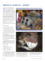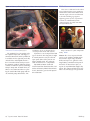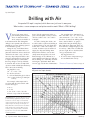
1
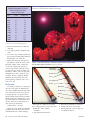
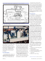
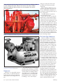
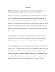
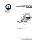
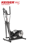
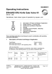
By John L’Espoir
V
Drilling with Air
Airspeed of 35 mph is required, while foam can just have its own pace.
What makes a screw compressor and piston machine work? What is DTHH drilling?
elocity is the most critical
part of drilling with air in the
direct circulation method.
Air is compressed and forced
to the bottom of the hole through the
drill pipe and expands at the bit to near
atmospheric pressure, blowing upward
in the annulus to get out.
Along the way, it will blow formation chips, water, and other hole occupants out of this hole. Please note that I
did not use the word “carry.” Air does
not carry chips. Chips will fall because
of gravity. An upward air velocity that
is equal to the fall speed will balance
that chip. A higher velocity will blow
it out of the hole at 34 to 58 mph. This
equates to 3000 to 5000 fpm annular uphole velocity for air drilling.
The formula is easy:
(D 2 – d 2) × 16.5 = cfm
D = bit size in inches
d = O.D. of flush joint pipe in inches
cfm = required cfm to get 3000 fpm
velocity.
then a 750 cfm compressor will be required. Actual uphole velocity at 100%
efficiency will be 750 ÷ 721 × 3000 =
3120 fpm.
Yes, hole-cleaning time before connection is still a requirement. Drilling at
a depth of 500 feet, the chip flying time
will be 500 ÷ 3120 × 60 seconds = 10
seconds. As soon as you cut off the air
supply, the chips start falling down.
Many drillers will have one or more
compressors and typically a 4½-inch
flush joint pipe is used. Do not use a
square shoulder tool joint style drill pipe
for air drilling. (See “Drill Pipe and Collar Designs,” April 2009 Water Well
Journal, page 54, for more information.)
The question arises: Just how big a
hole can I drill? (D 2 – d 2) × 16.5 = cfm
converts into D = √ (d 2 + cfm ÷ 16.5).
For direct circulation air drilling without
foam, consider Table 1 as “gospel.”
Many drillers brag on drilling larger
holes with their compressor. Some of
them will have enough integrity to call
me and say: “John, I hate to admit that
you were right. We are stuck bad, how
can I get my hammer out?”
My suggestions were:
●
Get one or more compressors to get
at least 5000 ft/min velocity.
TRANSFER OF TECHNOLOGY/continues on page 40
Figure 1. Many drill manuals include this chart to determine compressor size.
We prefer our simple formula.
For example, what compressor is
needed to drill an 8-inch air hole with
4½-inch O.D. pipe?
●
●
●
D=8
d = 4.5
(82 – 4.52) × 16.5 = 721 cfm.
If no air escapes into the formation,
John L’Espoir has enjoyed a 40-year career in
portable drilling equipment design. He holds
a bachelor of science degree in mechanical
engineering and was formerly the director of
engineering for the George E. Failing Co. in
Enid, Oklahoma. John was born in the Netherlands and moved to Enid in 1969. He is the
founder, owner, and president of Enid Drill
Systems Inc. He received the 2003 NGWA
Technology Award.
38/ September 2010 Water Well Journal
NGWA.org
Table 1
Maximum Diameters for Some
Popular Compressor Sizes,
Using 41⁄2-Inch Pipe
cfm
d Inch
D-Max Inch
1
71⁄8
71⁄2
81⁄8
81⁄2
85⁄8
91⁄8
95⁄8
101⁄2
117⁄8
131⁄8
141⁄4
500
600
750
850
900
1050
1200
1500
2000
2500
3000
4 ⁄2
41⁄2
41⁄2
41⁄2
41⁄2
41⁄2
41⁄2
41⁄2
41⁄2
41⁄2
41⁄2
Figure 2. Conventional three-cone bits.
Courtesy of GT Engineering, Shawnee, Oklahoma.
TRANSFER OF TECHNOLOGY/from page 38
●
●
●
●
Mix water/foam and try to float the
chips out.
Get a duplex pump to pump the hole
clean.
Get a crane large enough to pull your
pipe past the breaking point and hope
that it breaks close to the bit.
Fill the hole properly and start over.
The uphole velocity is strictly a function of the volume of the compressor
in cfm. The compressor capacity is
expressed as cfm/psi (900/350). Please
be aware that the cfm is the intake cfm
and not the volume at the rated pressure.
Atmospheric pressure equals 14.7 psi.
At 100% efficiency, ignoring altitude,
humidity, and temperature, the compressed package would be 900 × 14.7 ÷
350 = 37.8 cfm.
Figure 3. The down-the-hole hammer: (a) downstroke-drill position;
(b) upstroke-exhaust position. Courtesy of Numa.
Threaded
Connection
Backhead
Case
Feed Tube
Piston
Air Pressure
As stated previously, the compressed
air is forced to either the button bit tricone or the DTHH (down-the-hole hammer). The hammer does not eat the air;
it simply takes the energy stored in it,
and then turns it loose into the borehole.
Obstructions in the annular space, usually chips and water, will maintain some
pressure on the air, reducing this as it
comes to the top of the hole.
1 foot of water = 2.31 psi.
This is for clean, fresh water without
any kinds of solids. If the hole fills up
with formation water while making a
40/ September 2010 Water Well Journal
Blow Tube
Bit Bearing
Chuck
Bit
connection, the compressed air must
have enough pressure to overcome this
“hydrostatic” water column.
Example:
●
Rig shuts down for lunch.
●
●
●
Hole fills up with 460 feet of water.
Compressor is rated at 125 psi.
When putting the air to the pipe, no
circulation is noticed.
NGWA.org
Figure 4. (a) 350 cfm/220 psi deformed the kelly when using a DTHH. Both sub
and kelly required remachining. This was a tight connection. (b) The spindle on
the Dresser T70W is being ground down before the seal retainer can be removed.
Swelling was caused by 750/250 DTHH without a shock sub.
So, 460 ÷ 2.31 = 199 psi. A larger
compressor is needed, with reference
to the pressure rating—250 psi would
break the water column, blow out the
water, and drilling continues. An experienced driller will not shut down for
lunch; however, if the situation described in the example happens for
some reason, he would then pull 200
feet of pipe and try again. The water
column would now be 260 feet above
the bit or hammer (260 ÷ 2.31 = 112
psi). The 125 psi compressor would
break the water pressure and blow out
the water.
Quick connections and blowing after
each joint will get that bit back to the
bottom of the hole to continue air
drilling. Before selecting a compressor,
the pressure must be considered for:
●
●
●
Pressure required by the downhole
hammer
Maximum water column to be
expected in the hole
Cleaning of the bit.
TRANSFER OF TECHNOLOGY/continues on page 42
Figure 5. (a) Design A; (b) Design B; (c) Design C. Courtesy of NHM (North Houston Machine).
(a)
NGWA.org
(b)
(c)
Water Well Journal September 2010 41/
Table 2
LeRoi Air Compressor
Model 256 S2C
Figure 6. The LeRoi 250 series S2 (two stage) and SDS (single dual stage) are
found on many rigs for well developing (three cylinder models) and drilling with
air (six cylinder series). Courtesy of Comp Air.
rpm
hp
Capacity (cfm)
870
125
445
1000
156
510
TRANSFER OF TECHNOLOGY/from page 41
Penetration Rate
Figure 7. Schematic diagram of the air flow through compressor.
Courtesy of Comp Air.
Flow Control Valves
42/ September 2010 Water Well Journal
Let’s look at two basic but different
types of air drilling: conventional with
collars and button type tricones, and
down-the-hole jackhammer (known as
DTHH drilling).
The conventional three-cone bits
(Figure 2) for hard formation are either
a short tooth type or a tungsten carbide
button tooth. A lot of drill collar weight
is required to get proper chipping action. Weight of up to 8000 pounds per
inch of diameter may be needed. An
8-inch hole would require 8 × 8000 =
64,000 pounds of drill collars. Add the
drill pipe to get the string load and it
becomes obvious that a rig with a minimum hookload of 100,000 pounds is required. Air drills are not this big and
most rigs would have trouble putting
more than 30,000 pounds of pulldown
onto the string due to their limited rig
rear axle weight.
The DTHH is nothing more than a
jackhammer operated by air to get chisel
action at a slow rotary speed. A typical
air drill will have a very slow rotary
speed.
Years ago, the hammers commonly
used required 0 to 10 rpm and 250 psi.
With the introduction of the variable
speed hydrostat drives, the rpm has a
range from 0 to 125 rpm, whereas the
compressors have jumped from 250 to
300 to 350 to 450 to 500 psi.
How high will this go? In 2001, I
worked on a well rehabilitation project
requiring 4200 psi. The air compressor
was rated at 5000 psi. The psi in a hammer determines the energy of the blow
to the bit (chisel). A 5-pound hammer
could be seen as 125 psi making 350 psi
like a sledgehammer.
Downhole hammer suppliers came
right along with better steels, better tolerances, and better lubrication to use
these higher pressures. Rig manufacturNGWA.org
Figure 8. Typical piping diagram rig application. Courtesy of Comp Air.
energy hammers back into the drill
stem. Air rigs do not typically use more
than one or two drill collars. Pulldowns
are used to maintain pressure on the bit.
The reaction force energy will hammer
this pipe, up and up, right into the topdrive or swivel/bearings. With bigger
hammers, we see more premature bearing failures. Kelly and topdrive spindles
are hammered so badly that the material
swells (Figure 4).
The Shock Sub
Figure 9. Model 256 S2C installed on a Ewbank M-100-C operating in
the Sahara Desert, Egypt.
ers promptly modified designs to get
more horsepower, bigger trucks, bigger
PTOs and drives to get these larger
compressors on board. As a side effect,
the rigs became much larger and much
more expensive. Coupling a highpressure mobile compressor to your
old rig will have the same hammer
performance.
The DTH Hammer
The downhole hammer (Figure 3) is
a highly machined close tolerance machine tool. It will perform to predetermined cfm, psi, and lubrication. The
NGWA.org
piston has air grooves and channels to
direct the compressed air to either push
the piston up or blast it full speed down
to impact on the bit shank. It is this impact shock on the buttons that fractures
the rock formation. When specifying a
hammer, please know what bit size and
compressor will be used. Please keep
sand and dirt from getting inside your
drill pipe and pumping into the hammer,
and do not forget the lube system.
A bigger hammer and more air pressure will result in a bigger blow. Penetration rate will increase. What happens
to the hammer reaction force? This
To minimize the damage and isolate
this reaction force, our industry has
developed a series of subs (Figure 5).
Design A: This design is the most
effective. It is installed directly above
the hammer and isolates the reaction energy. Drill pipe connections do not hammer up or swell the tool joints. Shown
in Figure 5 is a 9-inch O.D. shock sub.
Design B: This design is installed
directly below the topdrive and is
cushioned only in the pulldown mode.
This flotation-type sub is used to let
the lower part move up as a pipe is unscrewed. It is very popular on rigs with
carousels, and keeps the hammer out of
your topdrive bearings and hydraulics.
Design C: This design is fully cushioned for both pulldown or holdback
applied drilling. It can either be a pure
shock sub as shown, or two cushions
can be taken out to get 2 inches flotation. It is installed below the topdrive.
Take note that a typical shock sub
mounted below the topdrive will have a
box-down connection to meet a pin-up
drill pipe. The author does not know of
any advantage to pin-up or pin-down
drill pipes.
Shock subs are available for pindown drill pipe as well as many different sizes of threads. NHM is currently
fabricating a 22-inch-diameter sub to
be installed behind a 32-inch Numa
hammer.
All shock sub designs must perform
the following duties:
1. Transmit full rotary torque.
2. Transmit full mast hookload capacity.
3. Seal air at maximum psi and
temperature.
4. Isolate the reaction energy.
TRANSFER OF TECHNOLOGY/continues on page 44
Water Well Journal September 2010 43/
Figure 10. A three-cylinder 250 psi model 253 S2 installed on a Mayhew 1000
is used to develop water wells. Note the tall receiver tank rated at 300 psi.
Operating in Nebraska. Mud and airlines are valved together. This requires
special maintenance.
Figure 11. Compressor module—no power. Courtesy of Sullair.
setting, the compressor delivers the
air volume based on the rpm of the
compressor.
When running at 1000 rpm, service
frequency, especially valve work, will
increase substantially. Consult the factory for more details. Do not overspeed
these compressors.
The SDS allows the operator to
switch from 250 to 50 psi.
For the lower pressure, open up the
shutoff to the second unloader with its
setting at 50 psi. Also switch two flow
control valves on the piping on the compressor. On the six-cylinder shown in
the diagram, this allows all six cylinders
to produce air on single stage compression. When pumping at 250 psi, the outside four cylinders will pump into the
two center cylinders for secondary compression. These two cylinders only increase the psi and do not add to the cfm
like they do at 50 psi. At 1000 rpm, the
delivery increases from 510 to 610 cfm
when switching to 50 psi.
The Screw-Type Compressor
TRANSFER OF TECHNOLOGY/from page 43
Compressors
While there are many different types
on the market, we will limit ourselves
to only the older design, the piston machine, and the newer design, the screw
type.
44/ September 2010 Water Well Journal
The LeRoi 250 series S2 (two stage)
and SDS (single dual stage) are found
on many rigs for well developing (three
cylinder models) and drilling with air
(six cylinder series). A smaller piston
compressor was reviewed in the June
2010 installment of the “Transfer of
Technology” series. At the 250 psi
Units are available as a complete
trailer-mounted unit, a skid package
with engine to mount on a rig, a skidmounted air module to be powered by
the rig, or individual components to
allow the engineer to put various components like airend, receiver tank, and
cooler in available space. While the
input speed on a screw compressor is
typically 2100 rpm, the actual screws
may operate at a much higher speed.
The tip speed of the lobes governs the
pressure. Single compression can reach
220 psi. The Sullair unit shown in Figure 14 actually has two sets of screws;
the larger set pumps into the smaller set.
In about 1986, the author designed an
air transportable 1500-foot water well
machine for the U.S. Army. The compressor was 350 cfm/220 psi. The pressure was by single stage compression
so that only one airend with one set
of screws was needed to save weight.
Because of the low profile of 8 feet
maximum height over mast and the
mounting on a 6×6 International truck,
the compressor was mounted in pieces.
The cooler was sideways with hydraulic
drive. The GHH airend model CF 128
(Figures 15 and 16) had an overdrive of
1.212 to 1, meaning that these screws
rotate at 2545 rpm when the truck
NGWA.org
Figure 12. Rotary screw compression. Courtesy of Sullair.
Because a rotary screw has a continuous rotary motion, it may be driven
by hydrostatic motors without any problems of pressure spikes, unlike the
reciprocating piston compressors with
on-off valves every revolution.
Rotary Speed
As mentioned before, the air drill rotary speeds have changed with the designs of more powerful higher pressure
hammers. Gone are the mechanical 10
speeds with four speed auxiliaries to the
rotaries to get down to below 10 rpm.
Let’s take a look at some basic differences between a mud rotary and an air
rotary drill (Table 3).
A combination rig becomes very
heavy, and usually the secondary function is very limited. Many mud rigs
have air compressors on board used for
well development and such. Bits and
hammers are very sensitive to weight
control and rotary speed.
Review with the product OEM to get
the recommended rpm, weight, and
compressor volume for maximum performance and life out of these components. How does the driller know if the
hammer is doing its job? With his ears!
The hammer will have a rhythm that is
music to the driller’s ears. (No, it is not
called hard rock or rap!)
The Injection Pumps
engine runs at 2100 rpm with the tranny
in 1 to 1.
Maximum speed for this oil-flooded
screw is about 4700 rpm. The basic dry
screw compressor was designed in the
1940s by SRM (Svenska Rotor Maskiner) in Sweden. Then came the oilflooded screw with the development of
a coalescent filter that is able to separate
the oil out of the compressed air. But
strangely enough, we add special oil
back into the air to lube downhole
equipment. Functions of the compressor
oil are:
●
●
●
Cooling of compressor
Lubrication of screws, bearings, and
gearbox
Sealing clearances between screws,
avoiding steel to steel contact.
NGWA.org
These include oil, water, foam, and
mixed water and foam concentrate.
The Basic System
1. Two screws rotate within a chamber.
2. Chamber is flooded with oil.
3. Coalescent removes oil and lets air
through.
4. Oil must be cooled in cooler.
5. Oil must be filtered and controlled;
flow of oil will maintain operating
temperature.
6. Throttle valve controls amount of
intake air and thus output cfm.
7. Air with oil comes into the tankseparator tangentially, spinning out
most oil like a centrifuge.
8. Drive clutch powers compressor
rotation. A closed throttle valve
allows the clutch to stay engaged
while no air is produced. There are
no unloader valves like on a piston
machine.
●
The Oil Pump
Our injection pumps, side by side,
are driven by air motors fed by the large
compressor. Flow is controlled by a needle valve and a pressure regulator limits
the pressure. The large pump delivers
water and foam.
As stated previously, use special oils
to inject into your air stream when
drilling. Conoco EP Rock Drill 100 has
a new name—Conoco Hydroclear Rock
Drill Oil 100. It is designed for jackhammers. It is formulated with high
viscosity index base oils and selected
additives to reduce oxidation in the
presence of compressed air. And it
is approved for downhole drilling
equipment.
Most rock drill oils are made from
petroleum products and as such are not
TRANSFER OF TECHNOLOGY/continues on page 46
Water Well Journal September 2010 45/
Figure 13. Schematic of screw compressor system. Courtesy of Sullair.
Figure 14. Sullair 750/350 installed on Ewbank model M-100-RD for reverse
airlift mud drilling. Also used to develop the well.
TRANSFER OF TECHNOLOGY/from page 45
classified as “H-1” food grade lubricants. When drilling water wells for
drinking water, we recommend a bottled
46/ September 2010 Water Well Journal
lubricant by Numa that is environmentally safe, biodegradable, and nontoxic,
and contains no petroleum distillates.
Simply pour one 8-ounce bottle into the
drill pipe when starting the hammer and
then add a bottle for every 300 feet of
drilling. A continuous water injection of
2 to 3 gpm is required. These quantities
are typical for a 6-inch hammer. This
lube works well for 8-inch hammers and
smaller and has been in use since 1988.
Another product for use in potable
water wells is made in Canada and
comes in 55-gallon drums and 5-gallon
pails for easy storage. The trade name is
Matex RDO 302 and it has been in use
in the United States since approximately
1991.
Shell Oil recommends their FM Gear
Oil 220, which is “H-1” approved, and
CITGO also has food grade gear lubes;
however, neither one has any records
of actually using these products in a
DTHH water well application. For nonwater well drilling, the following oils
have been used successfully with a
DTHH-type drilling:
●
●
●
●
Shell Torcula Oil 320
D-A Rockdrill Lubricant 500
Mobil Vactra Series
Hydrotex #207 and #208.
NGWA.org
Figure 15. Note that the input gear is not connected to the female rotor,
near side. Courtesy of GHH, Germany.
Air In
Overdrive
Air Out
Figure 16. The CF-128 coupled to a chain drive with air clutch. The valve in the
top air intake line controls the volume of the compressor and is called the throttle
control, which is automatically pneumatically controlled by the air tank pressure.
Once again, these are not rated for
food grade quality and we do not want
them in our water. Chevron-Texaco and
Exxon-Mobil do not make an “H-1”
food grade EP type lubricant for water
well hammer drilling.
Wear nose and mouth filters when
drilling with air to minimize your intake
of solids and the airborne oil mist particles, which can be hazardous to your
health.
NGWA.org
●
The Water Pump
Drilling with air stirs up a lot of dust.
To control the dust in dry holes, water
can be added to the airstream at a higher
pressure than the compressor. The water
converts the dust into mud balls. When
drilling with air, be sure to wear eye and
ear protection. Yes, you can still hear the
hammer operation.
Put in as little water as required by
the hole condition (water may be hard
to get at the drill site). A small pump at
8 gpm means 480 gallons per hour; four
hours of drilling is nearly 2000 gallons.
The pump must be variable volume delivery. The best drive will be a variable
speed hydraulic drive. With a fixed
drive, part of the delivery is piped back
to the tank through valving. This is a
waste of energy. The air motor concept
is good; however, it does take away
from the drill air cfm.
Some of the pumps frequently used
are the old twin piston Myers pump
(designs are now owned by Fred’s Water
Service). The model A08-4 produces
0 to 8 gpm at up to 400 psi. The pump
shaft eccentric provides a stroke of
0.688-inch and runs at maximum 360
rpm.
Other pumps include John Bean with
a choice of two, three, or four pistons
now sold as FMC Technology products.
CAT Pumps model 2020 has proven
to be very reliable on drilling rigs for
water injection. It offers a very simple
additional pump that injects foam
chemicals.
●
The Foam Pump
With the CAT triplex pump, it is very
simple to add a foam system.
The pump is a diaphragm design that
operates on the pressure in one of the
three cylinders and a spring will push it
back. Capacity is 0 to 1 quart per minute
and up to 1000 psi. There is no other
drive needed for this pump. Calibration
is by a built-in needle valve. Stainless
steel and brass are used to contain the
highly corrosive foam chemical—a
good reason to keep this out of your
water pump.
Drilling with foam greatly increases
the diameter of the well that can be
drilled with the air compressor on board
the rig. Air volume requirements drop
due to the lower uphole velocity of
approximately 45 to 150 fpm as compared to 3000 to 5000 fpm.
In a write-up by Bernard Higgins of
London from around 1975 to 1980, we
find a guide for borehole diameter vs.
cfm (Table 4).
Caution must be taken not to pump in
too much air. The air would simply find
a quick way out through the foam, and
cause many downhole problems.
The air/foam should come out of
the hole like a thick stream of shaving
cream, suspending and carrying the
chips. Adding bentonite to the foam will
TRANSFER OF TECHNOLOGY/continues on page 48
Water Well Journal September 2010 47/
Table 3
Basic Differences Between Mud Rotary and Air Rotary Rigs
Component
Mast hookload capacity
Rotary drive
Bore through swivel
Swivel capacity
Depth in feet
Horsepower of truck
Pump
Rotary speeds
Mud Rig
Air Rig
High
Table
Large
High
1500–2000
200–250
Duplex 51⁄2 ⳯ 8
50–160
Low
Topdrive
Small
Low
500–750
400–500
Compr 750–300
0–60
TRANSFER OF TECHNOLOGY/from page 47
turn the foam into a gel-type material
that improves borehole stability. Keep in
mind that the bentonite will have to be
washed out of your water well.
Foam is not recycled. Coming out of
the borehole, use a blooey line to divert
the flow away from the rig. Once again,
foaming agents are highly corrosive to
your drill. In a very short time, the foam
will break down and disappear while
your cuttings will be on the ground.
Well Development with Air
Figure 17. The oil pump.
After completing a well, having set
the screen and casing and having filled
the annular space properly with gravel
pack, hole fill material, and the top sanitary seal, the mud must be cleaned out
of the formation to provide clear, clean
groundwater.
A common method is to lower a pipe
into the casing and turn the compressor
on. It will build pressure, overcome the
hydrostatic water column pressure, and
blow the water out, surging fresh water
through the screen. After losing its air
pressure, the flow will stop, water column pressure restores, and so forth. The
cycling is automatic. The water column
is the on-off valve.
Jetting
Figure 18. Example of a water pump. Courtesy of Fred’s Water Service.
(An approach is used by Stewart
Brotheres in New Mexico. The following
report on jetting is submitted by David
Stewart, president of the company.)
We have done a lot of different things
over the years to develop wells: bailing,
surging, swabbing, airlifting, acidizing,
sand fracking, and jetting. In my opinion, jetting is the most effective way
to develop a well when it is completed
with wire wound screen. The triangular
shape of the wire makes jetting a natural
thing to do.
We build our own jetting tools. They
are very simple but very effective. We
take a short piece of casing, no more
than 4 to 6 inches in length, that will
just fit inside the wire wound screen we
want to develop. Three or four holes are
cut in the side, equally spaced around
the circumference and on the center line,
just large enough to accommodate a
¾-inch pipe collar. The pipe collars are
TRANSFER OF TECHNOLOGY/continues on page 50
48/ September 2010 Water Well Journal
NGWA.org
Figure 19. CAT model 2020 on Ewbank M-100-C in Egypt. Variable speed
hydraulic drive plus the additional foam injection assembly. The capacity
is up to 20 gpm and 800 psi.
Figure 20. Water injection. Courtesy of Sellers Co.
TRANSFER OF TECHNOLOGY/from page 48
inserted into the holes in the tool until
they are flush with the outside diameter.
Then they are welded in place, making
sure they are tangent and perpendicular
to the circumference of the circle and
taking care to protect the threads on the
inside of the collar.
Flat plates are usually welded on the
top and bottom of the tool. It is best to
cut these plates just a little smaller than
the outside diameter so that when the
plates are welded to the casing, it will
give a natural bevel to the corner instead
of a square corner that has to be ground
and beveled. The top plate should have
a hole cut in it to accommodate whatever threaded connection the driller will
be attaching to it.
50/ September 2010 Water Well Journal
When all the welding has been completed, threaded tungsten carbide hydraulic bit jets can be screwed into the
¾-inch pipe collars. These jets never
wear out, so we recommend welding
them to the pipe collar so there is no
danger of the jet backing out while in
use. The weld should be ground smooth
so there is nothing rough on the outside
diameter of the jetting tool that could
damage the wire wound screen.
The jetting tool should be run into
the casing to the bottom of the bottom
screen. The volume of fluid that is
pumped through the tool is a function of
the size of the jet and the volume and
pressure capability of the pump being
used to power the jet. Pump pressure
should be approximately 300 psi. The
jet should be rotated very slowly as it is
pulled back through the length of each
Figure 21. Foam injection.
Courtesy of Sellers Co.
Figure 22. Owner Thomas H. Oast told
me that he is one day older than his
rig, a Franks 1957 model KF-50. An
auxiliary foam system allows him to
use this system with the old WAH
compressor at 40 psi. Pictured in Oklahoma in 2002 drilling a 6-inch well.
screen. Making a second pass on each
screen can be effective as well. The top
of the sand pack should be monitored
throughout the jetting process and care
should be taken to keep the sand above
the top of the top screen. The removal of
fines and wall cake and the packing of
the sand and the removal of voids in the
sand will cause it to drop and additional
sand will need to be added. If it is not
NGWA.org
Figure 23. A mass of foam slowly moves down a hill in Oregon. A 900/350
compressor had no return air in this lava formation. The water injection pumped
pure foam concentrate downhole to get cuttings to come up. The foam flies out
of the blooey line in a steady flow. Depth reached was approximately 500 feet.
Pictures courtesy of STACO Well Drilling.
Table 4
Borehole Diameter Versus cfm
26⬙ Hole
15⬙ Hole
10⬙ Hole
6⬙ Hole
400–600 cfm
200–300 cfm
90–130 cfm
25–30 cfm
up to remove the fines from the casing
and prevent them from being circulated
back into a potentially productive formation. The reason jetting is one of the
best ways to develop a wire wound
screen is because it lets you expend the
hydraulic horsepower where the work
needs to be done, which is the same
reason the jetting of rock bits works so
well.
Do not try this system on wire wound
PVC screens.
Lubrication
These high-volume, high-pressure
compressors are very expensive, from
$60,000 to $120,000. Please know what
lubricant to put in and how often to
change fluid and filters. Fluids could
very easily be synthetics with a high
flash point. Remember, the oil also
transfers the heat.
Piping
possible to monitor the top of the sand
pack, then jetting probably should not
be done because it will probably expose
some of the screen to the borehole.
The basic principle of jetting is to jet
water through the screen into the sand
pack and disrupt it. With enough pressure and volume, the formation behind
the sand pack can actually be abraded or
sandblasted. The sand is disrupted and
NGWA.org
the fines are washed into the screen, and
as the jet moves up the screen the sand
below it settles in around the screen
very uniformly. Assuming circulation
can be maintained back to the surface,
the fines and possible wall cake will be
caught up in the fluid and circulated
back to the surface. If circulation does
not return to the surface, then some secondary pumping system needs to be set
Compressed air has a number of unwanted side effects. These include lots
of heat, making the full flow line hot to
the touch, and formation of condensation water. The compressor to flow line
connection should be a stainless steelreinforced hose designed for high temperatures, properly guarded. This hose
absorbs vibrations, dissipates heat,
and allows misalignments due to belt
tightening.
Next is the reservoir. These must be
ASME coded for the relief valve pressure setting. Do not ever weld on this
tank body unless you are an ASMEapproved welder.
The tank condensate should be
drained frequently and automatic drain
equipment is preferred. Lines and valves
get hot, and with the presence of moisture rust will form on the inside of lines
and valves. We recommend stainless
valves with “hi temp” ball seats such as
made by Inline Industries for maximum
TRANSFER OF TECHNOLOGY/continues on page 52
Water Well Journal September 2010 51/
Figure 24. A model Jed-A develops a large water well with a LeRoi 256
compressor.
TRANSFER OF TECHNOLOGY/from page 51
efficiency. Be sure to get full flow
valves for minimum friction (energy
loss). Stencil the word “Hot!” on these
components to warn hands could be
burned, followed by involuntary reaction jumps, possibly landing in even
more trouble. Put a screen guard around
these items.
●
●
●
Air and Mud Combination Piping
This is a difficult one. Even double
swing brass checks and ball valves will
eventually leak mud and sand into your
air tank. This mud will work its way
into the unloader valves on piston compressors and cause extreme pressure
buildup and pop the safety valve. When
mud is detected in the condensate, either
replace the checks and ball valves or
isolate the air to mud connection. If a
rig is equipped with this dual hookup,
we recommend that a small slobber pot
be installed on the tank to trap the mud
and keep it from going into the unloader
system lines.
Service and Operation
Suggestions
●
●
●
Check when the compressor was
last serviced with fresh lubricant and
filters.
If the compressor delivers oil with
the air, change the coalescent filter
immediately.
Clean or replace the air intake filters.
●
Figure 25. A Ewbank M-100-RD
develops a very large well with a
750/350 Sullair compressor. Note
the enormous difference in water flow,
meaning a much larger downhole
screen surge.
Photo by Gerry Neubecker III.
Check your pipe dope specs to make
sure it can be used for water wells.
Never use grease on tool joints.
Send the correct hammer oil with the
rig. Design a system that turns off the
water, foam, and oil injection when
the compressor tank pressure drops
below 25 psi. Be sure and thoroughly
clean oil-flooded wells.
Service related equipment such as the
water, foam, and oil injection system.
Check your air reservoir condensate
water for color, rust, and mud!
Resolutions to Make Today
1. Write a drill-air section on maintenance and stick with it.
2. Check your drilling program and see
if you have enough, too little, or too
much air. Watch out for diameter
changes in the borehole.
3. Have adequate filters and compressor
fluid on hand, with clear instructions
on how to add the fluid.
4. Determine what hammer lubricant
should be used.
5. Invest in a bit grinder and dress those
bits before sending them to the field.
Y
OLOG
CHN
OF TE
SFER
ries to
le se
TRAN
artic drilling
nical
nd
A tech understa ponents.
better ent com
s
equipm
onent
mp
Rig Co n
Drill
eratio
table
• Por n and Op
Tips
• Desig Sizing d Safety
per
an
• Pro enance
int
• Ma
NGW
re
A P
6. Contact the hammer manufacturer
to get proper lube specs and air volume/pressure for the DTHH.
7. Review if you need a shock sub.
8. Switch to nontoxic hammer lubes.
Coming next month: Drilling with
augers and buckets. No extra mud or air
for these holes. Why do some augers
have a hole on the centerline, and can
you get a patent on a hole in a tool?
Unless otherwise noted, all photos taken
by John L’Espoir.
Interested in the book Transfer of Technology?
It is available in the NGWA Bookstore.
The member rate is $75; the nonmember rate
is $87.50. Call NGWA at (800) 551-7379
to order your copy today.
ss
oir
. L’Esp
M. M
John
ieur
Ingen
52/ September 2010 Water Well Journal
NGWA.org
T
here must be thousands of reciprocating piston compressors
on drilling rigs today. The
major brands are Gardner Denver and LeRoi, while there are a lot of
Quincy and Joy units as well. Switching
over to the rotary screw type usually
means a contractor with a lot of deck
space can put on a compressor package
with its own engine. Typically, a new
trailer-mounted compressor will be required, which is costly with serious fuel
consumption. Of course, the new compressor will have more cfm and/or psi
as compared to the on-board piston
machine.
Some of the reasons why a screw
compressor does not fit as a replacement
are:
●
●
●
●
●
insufficient space
limited horsepower of engine
limited horsepower of drivetrain
inadequate speed of driveline
incorrect input rotation of driveline.
The above reasons are powerful reasons to maintain your compressor properly, repair it as required, and use the
proper lubrication.
Figure 1 shows a Gardner Denver
model 580 WCG. The rating is 580 cfm
at 50 psi at 870 rpm. The compressor
has six cylinders, all producing single
stage compression. This unit had been in
service for 30 years.
CompAir-LeRoi is now owned by
Gardner Denver. Their service manual
spells out a single-viscosity, nondetergent super refined oil with rust and oxidation inhibitors.
Figure 1. Courtesy of D.S.M., Austin, Texas
Figure 2. Courtesy of Rental Supply Co. of Grand Junction, Colorado
Grades of Oil
Ambient temperature range:
●
●
●
SAE 30—above 60°F
SAE 20—from 32°F to 60°F
SAE 10—below 32°F
A mineral-based oil will break down
over time with enough heat, causing severe carbon buildup on the compressor
valves. Figure 2 shows the outside of a
compressor that has been too hot. Inside
are either broken valves or valves that
NGWA.org
are completely covered with carbon.
LeRoi compressors run at 870 rpm
standard or about 1200 rpm maximum
speed, causing reduced life but increased volume. Running below 600
rpm is equally as bad since the oil is not
thrown up inside the cylinders to lubricate the pistons, liners, and rings.
TRANSFER OF TECHNOLOGY/continues on page 54
Water Well Journal September 2010 53/
Figure 3. Courtesy of Rental Supply Co. of Grand Junction, Colorado
Dedication
This series is dedicated to the education of John L’Espoir’s two grandsons,
Ethan Daniel Atwood and Elliott John
Atwood (right), who are each destined
to become a drilling rig engineer.
Opposing points of view or questions?
Contact us at Enid Drill Systems
(580) 234-5971, fax (580) 234-5980,
[email protected].
TRANSFER OF TECHNOLOGY/from page 53
The author believes in synthetic oils.
For a piston compressor, I strongly recommend a Rarus 827 made by Mobil. It
is available in 30 weight and practically
ends all of the carbon problems since
there is no mineral-based oil present in
the manmade synthetic lubricant. Figure
3 shows a LeRoi six-cylinder, dual-stage
250 psi compressor. In South Texas, we
find several contractors who are replacing the small LeRoi lube pump with an
external lube pump and oil filter. The
54/ September 2010 Water Well Journal
results have been excellent by the increased pressure on the lube system.
If you have a used compressor of this
type in the shed collecting dust, it might
be worth your time to try to sell it for
spare parts. Some of the parts are no
longer manufactured, increasing the
value of out-of-service compressors.
My thanks to Duane Cook and
Calvin Cook from Grand Junction, Colorado, and Stanley Martin from Austin,
Texas, who had a great deal of input in
this addendum.
Inspect and service your compressor
today. WWJ
Waiver: The views expressed in this
article are the author’s opinion and are
based on the engineering education,
skills, and experience gained in a lifelong industry commitment. No part of
this article is intended to replace or
supersede any information supplied by
others. The contents of this article may
not be used in any type of legal action.
NGWA.org