1
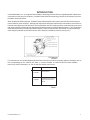
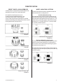
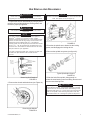
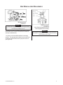
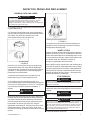
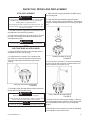
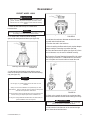
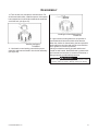
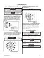
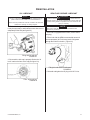
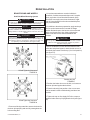
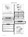
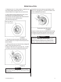
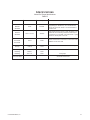
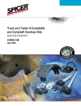
PreSet® Hubs Service Manual
Pre-Adjusted Bearings
Steer, Drive, and Trailer Applications
Table of Contents
Important Reminders ............................................................................................. 2
Introduction ........................................................................................................... 3
Identification ..........................................................................................................4
PreSet Wheel Hubs ................................................................................. 4
Wheel Mounting Systems ........................................................................ 4
Hub Pilot Wheel Mounting System ..............................................4
Ball Seat Wheel Mounting System ..............................................4
Periodic Inspection and Preventative Maintenance .................................................5
Visual Inspection - Oil Lubricated .............................................................5
Visual Inspection - Semi-Fluid Grease Lubricated .................................... 5
Functional Checks ................................................................................... 6
Hub Removal and Disassembly ........................................................................... 7-8
Inspection, Repair and Replacement ..................................................................... 9
Bearing Cups and Cones .......................................................................... 9
Wheel Studs ............................................................................................ 9
Stud Removal ...........................................................................................9
Stud Replacement ................................................................................... 10
ABS Tone Ring (As Applicable) .............................................................. 910
Reassembly - PreSet Wheel Hubs .................................................................... 11-12
Reinstallation ....................................................................................................... 13
Installing the PreSet Wheel Hub .............................................................. 13
Installing the Hubcap ............................................................................... 13
Oil Lubricant ............................................................................................ 14
Semi-Fluid Grease Lubricant ................................................................... 14
Brake Drums and Wheels ....................................................................... 15
Hub Pilot Wheel Mounting System .......................................... 15-16
Ball Seat Wheel Mounting System .......................................... 16-17
Specifications .................................................................................................... 18-19
IMPORTANT REMINDERS
Read this manual carefully, providing extra attention to its explanations and instructions. To
ensure safe, continuous, trouble-free operation, understand your wheel hub system, and keep
all components in proper operating condition. Pay particular attention to all NOTES, CAUTIONS, WARNINGS,
and DANGERS to avoid the risk of personal injury or property damage, and realize these statements are not
exhaustive. ConMet cannot possibly know or evaluate all conceivable methods in which service may be
performed or the possibly hazardous consequences of each method. Accordingly, those who use a
procedure not recommended by ConMet must first satisfy themselves that neither their safety nor the safety
of the product will be jeopardized by the service method selected. Use only ConMet approved replacement
parts. Do not attempt to use damaged parts. DISC WHEEL INSTALLATION PROCEDURES (ConMet part
number 103282), OIL DECALS (ConMet part number 106873), and SEMI-FLUID DECALS (ConMet part number
107383) are available upon request.
Notes
NOTE
These activities include additional information
that may assist the technician in service
procedures (see figure 1).
FIGURE 1
Cautions
These activities indicate that product damage may
result from failing to heed the stated advisory
(see figure 2).
!
CAUTION
FIGURE 2
Warnings
Associated activities indicate that personal injury may
result from failing to heed the advisory. Personal injury is
not equated to career-ending injury but may result in
possible change in quality of life (see figure 3).
!
WARNING
FIGURE 3
Dangers
Associated activities indicate that death or serious personal
injury may result from failing to heed the stated advisory.
Serious personal injury may be equated to career-ending
injury (see figure 4).
Consolidated Metco, Inc.
!
DANGER
FIGURE 4
2
INTRODUCTION
Consolidated Metco, Inc. is recognized as the leader in the design and manufacture of lightweight/low maintenance
components for the heavy truck industry. ConMet PreSet Wheel Hub technology offers the best solution to prevent
premature wheel hub failures.
When installed as OEM equipment, ConMet PreSet Hub Assemblies offer a three year/350,000 mile warranty on
tractors and five years on trailers. With periodic inspections and proper lubricant level maintenance, actual service
intervals can extend up to 500,000 miles. These assemblies include ConMet precision-machined hubs, premium oil
bath seals, specially toleranced roller bearings, and unique precision-machined bearing spacers. This combination
eliminates the need to manually adjust wheel end play. These components are delivered as a complete package,
eliminating the potential for premature failures due to improper installation practices (see figure 5).
TN Trailer Hub
FIGURE 5
For information on our standard lightweight aluminum or ductile iron hubs for manually adjusted bearings, refer to
the corresponding service manual (see table 1). Contact ConMet at 1-800-547-9473 for other available
technical or product information, or visit our web site at www.conmet.com.
Literature #
10005642
10005647
Description
PreSet Hub Assembly
Service Manual
ConMet Aluminum and Iron
Component Hub Service
Manual
Corresponding Literature
TABLE 1
Consolidated Metco, Inc.
3
IDENTIFICATION
PRESET WHEEL HUB ASSEMBLIES
WHEEL MOUNTING SYSTEMS
ConMet offers a complete family PreSet Wheel Hub
Assemblies for steer, drive, and trailer axles.
ConMet PreSet Wheel Hubs are available in both hub
pilot and ball seat nut configurations.
All ConMet PreSet Wheel Hubs come
complete with pre-installed bearings, cups
and cones, and oil seals. These hubs are
unique in that a precision tubular spacer is utilized
between the bearings, eliminating the need for manual
bearing adjustment (see figures 6-9).
Hub Pilot Wheel Mounting
The hub pilot wheel mounting system makes use of a
single two-piece flange nut on each wheel stud for both
single and dual wheel applications (see figure 10). The
hub pilot wheel mounting system is also known as the
Uni-Mount-10™ (10 stud), WHD-10™ (10 stud), WHD8™ (8 stud), and ISO system.
PreSet Steer Hub
FIGURE 6
Hub Pilot Mounting Systems
FIGURE 10
PreSet Drive Hub
FIGURE 7
Ball Seat Wheel Mounting System
The ball seat wheel mounting system makes use of the
spherical contact area between the nut and wheel to
both locate the wheel and hold the wheel tight against
the brake drum (see figure 11).
The ball seat wheel mounting system is also known as
the stud piloted, ball seat cap nut (BCN) and double cap
nut (DCN) system.
PreSet TN Trailer Hub
FIGURE 8
Ball Seat Mounting Systems
FIGURE 11
PreSet TP Trailer Hub
FIGURE 9
Consolidated Metco, Inc.
4
PERIODIC INSPECTION AND PREVENTIVE MAINTENANCE
ConMet requires a visual inspection of the PreSet Hub Assembly every 12 months or 100,000 miles.
NOTE
NOTE
ConMet requires PreSet wheel hub service at 500,000 mile
intervals or 5 years, whichever comes first.
In addition to the annual visual inspection, you should maintain
current shop preventative maintenance and pre-trip inspection
practices.
VISUAL INSPECTION
OIL LUBRICATED
SEMI-FLUID GREASE LUBRICANT
Visually inspect for leakage and oil contamination.
Visually inspect for leakage and grease contamination.
Leakage Indicators
1. Check to be certain that no oil is present around the
hubcap or on the wheel.
Leakage Indicators
1. Remove ConMet PreSet semi-fluid grease hubcap
(there is no sight window).
!
CAUTION
If oil is present, investigate the cause and take corrective action.
2. Check to be certain that no oil is present on the hub,
brake hardware, or brake shoes.
!
CAUTION
If oil is present, the seal may be defective, improperly installed, or
worn out. Replace the seal by following the instructions as
outlined in this manual.
!
CAUTION
Do not mix oil types. If oil needs to be added, make sure you use
the same type.
Oil Contamination
Allow any air in the oil to escape prior to inspection.
Visually inspect the lubricant for discoloration. Under
normal conditions, the oil will darken slightly. A white or
milky appearance indicates water contamination. If the
inspection indicates contamination, completely service
the PreSet Wheel Hub by following the instructions as
outlined in this manual.
Consolidated Metco, Inc.
2. Inspect the outer bearing to make sure sufficient
grease is present and that there is no sign of
contamination.
3. If additional grease is required, use the fill hole in the
barrl of the hub to add grease until it is clearly migrating
through the outboard bearing.
!
CAUTION
DO NOT mix grease types. If grease is added make sure it is the
same type installed by the OEM.
Grease Contamination
Visually inspect the grease for discoloration. Under
normal conditions the grease may darken slightly. A
white or milky appearance indicates water
contamination. If the inspection indicates
contamination, completely service the PreSet Hub by
following the instructions in the manual.
5
PERIODIC INSPECTION AND PREVENTIVE MAINTENANCE
FUNCTIONAL CHECKS
In addition to the Annual Inspection, the following
functional checks should be done in conjunction with
brake or tire service.
NOTE
Conduct the following inspections with the wheel(s) and drum
removed.
! WARNING
Never work under a vehicle supported by a jack without
supporting the vechicle with stands and blocking the wheels.
Rotate the hub and check for free, smooth, and quiet
rotation. If rotation is hampered, PreSet Hubs should be
serviced immediately.
Measure End Play
1. Remove the hubcap, and use a dial indicator with a
magnetic base mounted on the spindle end, to read the
travel at the hub cap mounting surface (see figure 12).
Checking for End Play
FIGURE 12
2. Grasp two wheel studs across from each other and
pull and push the hub while oscillating it.
3. Measure the end play by the difference between the
minimum and maximum dial indicator readings.
! CAUTION
PreSet Hubs should be serviced if end play exceeds 0.006”.
Consolidated Metco, Inc.
6
HUB REMOVAL AND DISASSEMBLY
! WARNING
Never work under a vehicle supported by a jack without
supporting the vechicle with stands and blocking the wheels.
NOTE
If the hub to be disassembled is a drive hub, remove the drive axle
shaft, and capture the oil (see figure 15).
1. Prepare the axle for disassembly by using a jack to
raise the axle until the wheels are off the ground, and
the axle is properly supported.
! CAUTION
Care should be taken to avoid damaging the hub or other
components.
NOTE
If you plan to replace the brake drum (i.e., cast in place of
CentrifuseTM or wheels (i.e., aluminum in place of steel),
measure stud standout (see figure 13). In hub piloted mounting
systems, the studs must be long enough for the threads to be
exposed beyond the installed wheel nut. In the ball seat
mounting system, the stud length beyond the brake drum should
be from 1.31” - 1.44” as measured from the brake drum to the
end of the stud. Call ConMet at 1-800-547-9473 for the correct
stud part number for your application.
If you plan to replace the brake drum, verify the new drum has
the same drum pilot diameter as the one that has been
removed.
Removing the Drive Axle Shaft
FIGURE 15
3. Examine the spindle nut to determine the locking
system, and disengage the locking device.
4. Remove the spindle nut system (see figure16).
Typical Spindle Nut System
FIGURE 16
Measuring Stud Standout
FIGURE 13
2. Remove the wheels and brake drum (see Figure 14).
5. Slide the hub off the spindle, being careful to
protect the outer bearing cone from falling. Remove and
save the outer bearing cone.
! CAUTION
Occasionally, the seal can become stuck on the spindle, making
the hub difficult to remove. If mechanical assistance is required
to remove the hub, care should be used to avoid damage to hub
components (see figure 17). In some cases, part of the seal will
remain on the spindle. When removing this portion of the seal,
care should be taken not to damage the spindle or seal journal.
Removing the Wheels
FIGURE 14
Consolidated Metco, Inc.
7
HUB REMOVAL AND DISASSEMBLY
Mechanical Puller
FIGURE 17
NOTE
ConMet makes several tools to assist in the removal of hubs.
These tools are available for purchase and are listed in the back
of this manual (see tables 6 and 7).
6. Place the hub on its outboard end and remove and
discard the seal (if it does not need to be retained for
warranty rembursement).
Hub Disassembly
FIGURE 18
(Inner Bearing Retainer is not on
Hubs equipped with CR Seals)
NOTE
All components replaced under warranty must be returned for
consideration of reimbursement. Contact the OEM manufacturer
for their warranty return policy.
7. If present, remove and discard the inner bearing
retainer. The stamped steel retainer secures the inner
cone during shipment and has no purpose in service
(see figure 18).
Consolidated Metco, Inc.
8
INSPECTION, REPAIR AND REPLACEMENT
BEARING CUPS AND CONES
!
CAUTION
If a bearing cup or cone shows signs of deterioration, replace
the suspect part along with the mating component. Use the
appropriate replacement parts to ensure proper bearing
adjustment (see table 5). When reinstalling cups, be certain they
are pressed fully against their seats.
1. Thoroughly clean and degrease all components with a
nonflammable solvent.
2. If required on an aluminum hub, remove the bearing
cup by welding a large bead around the bearing surface
of the steel cup, letting the assembly cool, and
removing the bearing cup (see figure 19).
Bearing Cup Pressed into Hub
FIGURE 20
6. Iron hubs do not need to be heated for bearing cup
installation. Press the bearing cup into the hub using
the appropriate assembly aids.
WHEEL STUDS
Welding Bead
FIGURE 19
On an iron hub, remove the bearing cup using a large
hammer and a heavy drift, along with the appropriate
cup knockout tool, as listed in the back of this manual
(see table 7). Take precaution to avoid damaging the
bearing cup bore and shoulder.
3. Inspect the bearing cup bore for evidence of cup
rotation (spun cups). If noted, replace the hub.
4. To install a new cup in an aluminum hub, it is
recommended that the hub be heated evenly throughout
in an oven or in boiling water to 175-215° F. Cooling the
cup in a freezer will further ease the installation, if
desired.
! CAUTION
Do not overheat the hub.
Remove the aluminum hub from the oven or water and
carefully drop in the new bearing cup being certain it is
fully seated. Variations within tolerances of materials
and oven temperatures may require the bearing cup to
be pressed in to the hub (see figure 20) using the
appropriate assembly aids, as listed in the back of this
manual (see table 6). If the cup is loose, allow a few
seconds for it to heat up and secure itself before moving
the hub.
Consolidated Metco, Inc.
Replace all wheel studs that have damaged or distorted
threads, are broken or bent, or are badly corroded. Also,
replace both studs adjacent to the damaged stud. If two
or more studs have damage, replace all the studs in the
hub. Broken studs are usually an indication of
excessive or inadequate wheel nut torque.
Inspect the drum pilots, wheel pilots, and mounting face
on the hub for damage. A damaged drum pilot is usually
caused by improper drum mounting. A damaged wheel
pilot could be the result of inadequate wheel nut torque,
allowing the wheels to slip in service. Also inspect the
wheels and brake drum for damage.
STUD REMOVAL
! WARNING
Observe all warnings and cautions for press operation provided
by the press manufacturer to avoid serious personal injury and
damage to components.
1. Place the clean hub in a shop press with the hub
supported evenly around and adjacent to the stud being
removed.
! WARNING
Failure to adequately support the hub can result in physical injury
and/or damage to the hub.
! CAUTION
Some hubs are configured so it is impractical to have supports to
prevent the hub from tipping when force is applied to the stud. In
this case, support the hub on wood blocks on the floor and use a
heavy hammer to drive the studs out with several sharp blows.
Be careful to avoid damaging the hub and components, particularly the seal bore and the ABS tone ring.
2. Press the stud out of the hub.
9
INSPECTION, REPAIR AND REPLACEMENT
STUD REPLACEMENT
! CAUTION
On the ball seat wheel mounting system, always use left-handed
threaded studs on left-handed hubs, and use right-handed
threaded studs on right-handed hubs.
The ConMet part number is located on the head of the stud. The
same part number must be used for replacement unless changing
the drum or wheel type.
4. Place the hub in a press and place the ABS ring on
the hub ring seat.
5. Using ConMet ring installation tool part number
107119, center the tool over the ABS ring. Each type of
ring fits a corresponding diameter on the tool (see figure
22).
1. To install a new stud, support the hub evenly around
and adjacent to the stud being installed.
2. Press the new stud all the way into the hub. Be sure
the stud is fully seated and that the stud head is not
embedded into the hub.
! WARNING
If the stud head is embedded into the hub, the hub should be
replaced.
ABS TONE RING (AS APPLICABLE)
1. Inspect the ABS Tone Ring for any damage caused
during hub removal or hub servicing.
2. If replacement is necessary, use a small pry bar
(see figure 21) or hammer to gently remove the ring,
using a circular pattern around the ring to prevent
cocking.
Installing the ABS Tone Ring
FIGURE 22
6. Press the ring on the hub. If a press is not available,
drive the ring on with a hammer or mallet until the ring
seats on the hub (see figures 22-23).
Using Pry Bar to Remove ABS Ring
FIGURE 21
3. Thoroughly clean and degrease the ABS ring seat on
the hub with a nonflammable solvent.
! CAUTION
Replace the hub if the ABS ring seat is damaged.
The ABS ring must be fully seated with a maximum of 0.008” axial
runout to ensure the ABS system functions properly.
NOTE
For steer hubs, be certain the inside diameter flange is facing up.
Using a Hammer to Install the Ring
FIGURE 23
7. Inspect the ring to ensure proper seating. If the ring
is not completely seated, continue to drive the ring with
the ring installation tool until the ring is completely
seated.
A dial indicator can be used once the hub is reinstalled
on the spindle to check axial runout.
Consolidated Metco, Inc.
10
REASSEMBLY
PRESET WHEEL HUBS
! CAUTION
When using an oil bath system, do not pack the bearing with
grease. Grease will prevent the proper circulation of axle
lubricant and can cause premature wheel seal and bearing
failure.
1. Place the hub seal end up on a clean work
bench surface.
NOTE
If you are working on a drive or trailer hub, go to step 3. If you
are working on a steer hub, proceed as follows.
2. For steer hubs, install the tubular bearing
spacer with the tapered end down (see figure 24).
Bearing Cone Assembly for Drive Hub
FIGURE 25
4. Lubricate the seal outer diameter and the hub seal
bore with wheel end lubricant.
5. Position the seal in the hub bore.
6. When installing the Dana wheel seal, tap the adapter
plate around the outer edge to position the seal.
7a. Drive the Dana seal into place (see figure 26). Once
the tool bottoms out, the seal is installed correctly.
7b. Press the Chicago Rawhide Scotseal Plus XL wheel
seal evenly into the bore. If additional force is needed,
use a flat plate and a small mallet to install the seal.
Bearing Cone Assembly for Steer Hub
FIGURE 24
3. Lubricate the inner bearing cone with the proper
wheel end lubricant and install it into the inner bearing
cup (see figure 25).
NOTE
The seal must be replaced every time the hub is removed from the
spindle.
Do not apply any gasket sealant to the seal outer or inner
diameter.
Always use the seal installation tool specified by the seal
manufacturer. Using an improper tool can distort or damage the
seal and cause premature seal failure.
If using the Dana Outrunner Wheel Seal, place the seal with the
“air side” facing the adapter plate of the installation tool.
If using the Chicago Rawhide ScotSeal Plus XL Wheel Seal, no
special installation tools are required.
Eaton Seal
CR Scotseal Plus XL
FIGURE 26
8. Check to be certain the seal is not cocked and that
the seal inner diameter and the inner bearing turn freely.
! CAUTION
Failure to lubricate the inner diameter of the seal, and the seal
journal, may result in premature seal failure.
9. Lubricate the inner diameter of the seal with a light
film of clean wheel end lubricant.
Consolidated Metco, Inc.
11
REASSEMBLY
10. Turn the hub over, and place it seal end down. For
all drive and trailer hubs, install the spacer. If the spacer
has a tapered end, it should face towards the outboard
end of the hub. (see figure 27).
Installing the Outer Bearing Cone
FIGURE 28
Installing the Spacer
FIGURE 27
11. Lubricate the outer bearing cone with the proper
wheel hub lubricant and install it into the hub assembly
(see figure 28).
12. Light corrosion fretting that forms on spindles is
normal and should be removed with a fine abrasive.
When the residue is cleaned away, the bare spindle is
again subject to corrosion and must be covered with a
film of grease for corrosion protection,
making sure both the bearing journals and the seal
journal are well coated. Standard Grade 2 greases work
well in normal environments. In severe environments, a
Moly-grease may provide added protection.
!
CAUTION
Failure to apply grease to the bearing journals will result in fretting
corrosion, which may result in difficulty removing the bearing.
Consolidated Metco, Inc.
12
REINSTALLATION
INSTALLING THE PRESET WHEEL HUB
! CAUTION
Never support the hub on the spindle with just the inner bearing
and seal. This can damage the seal and cause premature failure,
i.e., by cocking the seal in the bore.
3. Install the inner spindle nut and torque to 300 Ft.
Lbs. (see figure 31).
NOTE
Do not back off the spindle nut.
NOTE
If you are working on a steer or trailer hub, go to step 2. If you
are working on a drive hub, proceed as follows.
1. For drive hub installation, place the hub horizontal,
and remove the outer cone and spacer. Fill the cavity,
through the end of the hub with the axle flange studs,
with as much oil as possible. If a lubricant fill hole is
available, lubricant can be installed after assembly.
Reinstall the spacer and outer cone in the hub (see
figure 29).
Reinstalling the Spindle Nut
FIGURE 31
4. Engage any locking device that is part of the spindle
nut system. If the locking system cannot be engaged
when the nut is at 300 Ft.•Lbs., advance the nut until
engagement takes place and the nut is locked. If a
double nut or jam nut system is being used, bend the
lock tab or install the set screw after the outer nut is
torqued to 200 Ft.•Lbs.
Prelubricating the Drive Hub
FIGURE 29
2. Mount the hub assembly onto the axle spindle with a
smooth, firm motion while holding the outer bearing in
place. Use care to maintain alignment between the
bearing cones, spacer, and spindle and to avoid seal
damage (see figure 30).
!
CAUTION
Once the hub is on the spindle, do not remove the outer bearing.
Removing the outer bearing may cause the seal to become
misaligned, resulting in premature seal failure.
INSTALLING THE HUBCAP
NOTE
The hubcap bolt holes must be free of debris, such as silicon
gasket sealer to ensure the bolts will tighten properly to avoid
leaks. The vent should also be clean and free of debris. Remove
any burrs or sharp edges. Always use new gaskets.
1. Install the hubcap. A ConMet PreSet hubcap is
available for trailer hubs to aid in identification of the
assembly in the field.
NOTE
Use SAE Grade 5 bolts or stronger. Do not use star washers or
split lock washers as they will allow contaminants to corrode the
threads. Use only flat washers with no locking features.
2. Torque the hubcap bolts to 12-18 Ft.•Lbs., using a
star pattern.
! CAUTION
If you are using semi-fluid grease, special procedures must be
followed as outlined in the “Semi-Fluid Grease Lubricant” section.
Mounting the Assembly
FIGURE 30
Consolidated Metco, Inc.
13
REINSTALLATION
OIL LUBRICANT
NOTE
Use any oil approved for use with manually adjusted bearings
(refer to trailer or tractor OEM for oil recommendations).
Some hubs are provided with a fill hole, located in the barrel and
between the bearings for adding lubricant.
1. Fill the hub through the hubcap or the fill hole with oil.
It may be necessary to add lubricant more than once to
adequately fill the hub (see figure 32).
SEMI-FLUID GREASE LUBRICANT
! WARNING
Failure to fill and maintain the hub with the correct amount of
semi-fluid grease may cause premature failure of the wheel hub
system, bearing failure and possible loss of the wheel and will
void your warranty.
NOTE
Please refer to TMC RP 631A for the recommended fill and
maintenance procedures.
1. If the hub is equipped with a fill hole, remove the fill
hole plug.
2. Fill the hub with the OEM recommended amount of
room temperature (60° F minimum) semi-fluid grease
through the fill hole in the hub. (Figure 25)
Filling the Hub with Oil
FIGURE 32
2. Be certain the hub cap is properly filled to the “oil
level” mark on the face of the cap (see figure 33).
Filling Hub with Semi-Fluid Grease
FIGURE 25
3 . Reinstall and tighten the fill plug to 20-25 Ft.•Lbs.
Fill to “Oil Level Line”
FIGURE 33
Consolidated Metco, Inc.
14
REINSTALLATION
BRAKE DRUMS AND WHEELS
Hub Pilot Wheel Mounting System
!
CAUTION
The brake drum must be fully seated on the drum pilot and against
the hub face during and after installation of the wheel(s).
NOTE
If your shop practice requires the use of lubricant or anticorrosion material to the threads and/or the drum pilot area, avoid
getting lubricant on the flat mating surfaces of the hub, drum, and
wheels.
!
WARNING
Always tighten the top nut first to fully seat the brake drum on the
drum pilot and against the hub face. See the adjacent diagram for
bolt tightening sequence, and tighten in order from 1 through 8 or
10, depending on the bolt pattern (see figures 35-36).
2. In environments where a corrosion inhibitor is
beneficial, ConMet recommends the use of Corrosion
Block, a product of Lear Chemical Research, (905)
564-0018. In severely corrosive environments, a light
coat of Corrosion Block on the drum and wheel pilots
has proven beneficial.
3. In addition to the above preparation, apply two drops
of oil to a point betweeen the nuts and nut flange
washer and two drops to the last two or three threads
at the end of each stud. Also, lightly lubricate the
pilots on the hub to ease wheel installation and
removal.
! CAUTION
Do not get lubricant on the mounting face of the drum or wheel.
Failure to clean lubricant from these surfaces may result in
decreased clamping load.
4. Before installation of brake drums and wheels that
utilize the hub piloted system, rotate the hub so one of
the wheel pilot bosses is at the top (12 o’clock position)
(see figure 37).
10 Stud Tightening Sequence
FIGURE 35
Rotating the Hub
FIGURE 37
5. Position the brake drum over the hub, so it seats on
the drum pilot and against the hub face.
6. Place the wheel(s) into position. One or more nuts
can be started in order to hold wheel(s) and drum into
position.
8 Stud Tightening Sequence
FIGURE 36
7. Tighten the top nut first. Apply 50 Ft•Lbs. torque to
draw the brake drum up fully against the hub (see figure
38).
1. Remove all foreign material to ensure the drum fits
the drum pilot properly and can fully seat against the
hub mounting face.
Consolidated Metco, Inc.
15
REINSTALLATION
Reinstalling the Wheel
FIGURE 38
8. Install the remaining wheel nuts and using the
sequence as shown, torque all the nuts to 50 Ft.•Lbs,
then retorque to 450-500 Ft.•Lbs. (see figures 35-36).
The last nut rotation must be with a calibrated torquing
device.
9. Inspect the brake and wheel installation by checking
the seating of the wheel(s) and drum at the pilots, and
by turning the wheel(s) and checking for any irregularity.
!
DANGER
Excessive or inadequate wheel nut torque can result in a failure
of the wheel mounting system. After the first 50-100 miles,
retorque all the nuts to 450-500 Ft.• Lbs.
Ball Seat Wheel Mounting System
Clean all mating surfaces on the hub, drum,wheels and
nuts. Remove loose paint, scale, and any material
building around the pilots of the drum, hub, and wheels.
Be sure paint is fully cured on recently refurbished
wheels.
NOTE
When dual wheels are mounted, the stud length beyond the brake
drum (standout) should be from 1.31-1.44” as measured from the
brake drum to the end of the stud (see figure 39).
Stud Standout
FIGURE 39
Aluminum Wheels
ALCOA Cap Nut Number
3/4-16” Threaded
Studs
5995 R and 5995 L or
5554 R and 5554L,
depending on stud length
Single Aluminum Wheel Applications
TABLE 3
BATCO Cap Nut Number
Steel Wheels
13-3013 R and 13-3013 L
3/4-16” Threaded
Studs
Single Steel Wheel Applications
TABLE 4
1 . When installing the inner dual, verify the inner nuts
being used are suitable for the application: aluminum
wheels, steel wheels, brake drum thickness.
!
CAUTION
Inner cap nuts must be deep enough to ensure the stud will not
bottom inside the nut and must be of a configuration approved by
wheel manufacturer.
2 . Rotate the hub to bring a drum pilot to the top (12
o’clock) position (see figure 40). Position the inner
wheel and tire assembly over the studs against the
drum
When mounting dual aluminum wheels, use ALCOA inner cap nuts
5978R and 5978L or the equivalent. These nuts can also be used
with longer studs up to 1.88” standout.
For special single aluminum wheel applications on drive and trailer
hubs, use ALCOA single cap nuts 5995R and 5995L or 5554R and
5554R and 5554L or the equivalent, depending on the stud thread
length (see table 3).
For single steel wheel applications, use BATCO 13-3013R and 133013L or the equivalent (see table 4).
Rotating the Wheel Pilot to 12 O’Clock
FIGURE 40
Consolidated Metco, Inc.
16
REINSTALLATION
3 . Beginning in the 12 o’clock position, install the inner
cap nuts by hand to ensure they are not
cross-threaded. Do not tighten any nuts at this time.
7. Install the outer wheel and nuts and tighten to 450500 Ft.•Lbs. (see figure 43). The last nut rotation must
be with a calibrated torque device.
4 . Apply sufficient torque (about 50 Ft.•Lbs.) to the
inner top cap nut to draw the brake drum
up on the drum pilot and against the hub and seat the
ball seat of the nut into the ball socket
of the wheel (see figure 41).
Torquing the Outer Wheel Nuts
FIGURE 43
8. Inspect the brake and wheel installation by checking
the seating of the wheel(s) and drum at the pilots and
by turning the wheel(s) and check for any irregularity.
Tightening the Inner Cap Nuts
FIGURE 41
5 . To properly center the wheel, lightly tighten the
remaining wheel nuts. Verify the drum is in place over
the drum pilots.
!
DANGER
Excessive or inadequate wheel nut torque can result in a failure
of the wheel mounting system. After the first 50-100 miles,
retorque all the nuts to 450-500 Ft.• Lbs. Always remove the
load from the wheels by jacking the truck or trailer up when
retorquing. Loosen the outer nuts to retorque the inner nuts.
6 . Starting with the top nut first and using a staggered
pattern, torque the inner wheel nuts
in stages to 450-500 Ft•Lbs. (see figure 42). The last
nut rotation must be with a calibrated torque device.
Torquing the Inner Wheel Nuts
FIGURE 42
NOTE
Use the appropriate nuts with the above technique to install the
front and outer dual wheels. Follow your shop practice to locate
the valve stems.
Consolidated Metco, Inc.
17
SPECIFICATIONS
Service Parts List
TABLE 5
NOT E: BEARING CUPS & CONES M UST BE REPLACED AS A SET !!!
FF Front Steer Axle
ConM et PART
NUMBER
107500 Bearing
Set
107501 Bearing
Set
103592
10005430
10005434
107551
107545
TN Trailer Axle
DESCRIPTION
ConM et PART
NUMBER
DESCRIPTION
NP026773 Inner Cup
NP899357 Inner Cone
NP435398 Outer Cup
NP874005 Outer Cone
PreSet Spacer
PreSet Oil Seal / CR 35058
PreSet Rebuild Kit (CR Seal)*
PreSet Oil Seal / Outrunner 847
PreSet Rebuild Kit (Outrunner Seal)*
107504
Bearing Set
107500
Bearing Set
104144
10005432
10005436
107553
107548
NP503727 Inner Cup
NP965350 Inner Cone
NP026773 Outer Cup
NP899357 Outer Cone
PreSet Spacer
PreSet Oil Seal / CR 46300
PreSet Rebuild Kit (CR Seal)*
PreSet Oil Seal / Outrunner 859
PreSet Rebuild Kit (Outrunner Seal)*
TP Trailer Axle
R - Series Drive Axle
ConM et PART
NUMBER
DESCRIPTION
107502 Bearing
Set
107503 Bearing
Set
103593
10005431
10005435
107552
107546
NP363298 Inner Cup
NP034946 Inner Cone
NP053874 Outer Cup
NP840302 Outer Cone
PreSet Spacer
PreSet Oil Seal / CR 47692
PreSet Rebuild Kit (CR Seal)*
PreSet Oil Seal / Outrunner 861
PreSet Rebuild Kit (Outrunner Seal)*
ConM et PART
NUMBER
DESCRIPTION
107506
Bearing Set
107506
Bearing Set
104412
10005433
10005437
107554
107550
NP593561 Inner Cup
NP174964 Inner Cone
NP593561 Outer Cup
NP174964 Outer Cone
PreSet Spacer
PreSet Oil Seal / CR 42627
PreSet Rebuild Kit (CR Seal)*
PreSet Oil Seal / Outrunner 851
PreSet Rebuild Kit (Outrunner Seal)*
*N ote: PreSet rebuild kits include all bearing cups & cones, spacer and oil seal.
Assembly Aids Kit (Part No. 107508)
TABLE 6
Part No.
107526
Description
Cup Pusher Trailer TN Inner
NP503727
Qty.
1
Part No.
Description
Qty.
107529
1
107527
Cup Pusher Trailer TN Outer
Steer Inner, NP026773
1
Cup Pusher Trailer TP Inner or
Outer
NP593561
107530
Cup Pusher Steer Outer, NP435398
1
107528
107531
Cup Pusher Drive Inner, NP363298
1
1
Cup Pusher Drive Outer, NP053874
Dissembly Aids Kit (Part No. 107532)
TABLE 7
Part No.
107533
Description
Cup Knockout Trailer TN Inner
NP503727
Qty.
1
Part No.
Description
107537
Cup Knockout Drive Inner
NP363298
107534
Cup Knockout Trailer TN Outer
NP026773
1
107538
Cup Knockout Drive Outer
NP053874
1
107535
Cup Knockout Steer Outer
NP435398
1
107539
Cup Knockout Trailer TP
(Inner or Outer), NP593561
1
107536
Cup Knockout Steer Inner
NP026773
1
Consolidated Metco, Inc.
Qty.
1
18
SPECIFICATIONS
Wheel End Torque Specifications
TABLE 8
Item
Measurement
Ball Seat
3/4-16
Torque
Notes
450-500
Always tighten the top nut first. If lubricant is used,
apply sparingly on threads only. Do not lubricate the
faces of the hub, drum, wheel, or on the ball seats of
the wheel nuts
22mm x 1.5 mm
450-500
Always tighten the top nut first. Apply two drops of oil
between the nut and nut flange, and two or three drops to
the outermost 2 or 3 threads of the wheel studs. Lightly
lubricate the wheel pilots on the hub.
Drive Studs
3/4-16
40-60
Drive Studs
5/8-18
40-60
Hub Cap
5/16-18
12-18
Oil Fill Plug
1/4 NPT
20-25
3/8 NPT
20-25
-
20-25
O-Ring Style.
Wheel Nut
Hub Pilot
Wheel Nut
Consult manufacturer’s instructions for drive axle shaft
installation for all drive studs
Drive Studs
Oil Fill Plug
Oil Fill Plug
Disc Brake Rotor
Consolidated Metco, Inc.
9/16 - 18
Minimum SAE Grade 5 fasteners, flat washers only
-
See brake manufacturer.
19
Consolidated Metco, Inc.
13940 N Rivergate Blvd, Portland, OR 97203
Phone: 800-547-9473; Fax: 503-240-5488
www.conmet.com
ConMet Part No.10005642
Rev. B 6/03