1
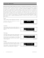
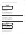
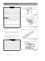
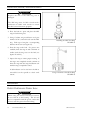
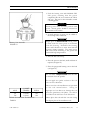
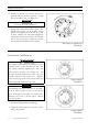
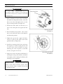
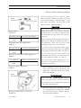
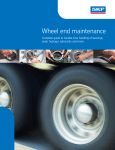
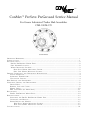
™
ConMet™ PreSet® PreGreased Service Manual
For Grease Lubricated Trailer Hub Assemblies
CMI-100M-199
CONTENTS
I M P O R T A N T R E M I N D E R S . . . . . . . . . . . . . . . . . . . . . . . . . . . . . . . . . . . . . . . . . . . . . . . . . . . . . . . . . . . . . . . . . . . . . . . . . . . . . . . . . . . . . . . . . . . . . . . . . . . . . . . . . . . . . . .i
INTRODUCTION.....................................................................................................1
IDENTIFICATION ....................................................................................................2
P R E S E T P R E G R E A S E D W H E E L E N D S . . . . . . . . . . . . . . . . . . . . . . . . . . . . . . . . . . . . . . . . . . . . . . . . . . . . . . . . . . . . . . . . . . . . . . . . . . . . . . . . . . . . .2
P A R T N U M B E R L O C A T I O N . . . . . . . . . . . . . . . . . . . . . . . . . . . . . . . . . . . . . . . . . . . . . . . . . . . . . . . . . . . . . . . . . . . . . . . . . . . . . . . . . . . . . . . . . . . . . . . . . . .2
W H E E L M O U N T I N G S Y S T E M S . . . . . . . . . . . . . . . . . . . . . . . . . . . . . . . . . . . . . . . . . . . . . . . . . . . . . . . . . . . . . . . . . . . . . . . . . . . . . . . . . . . . . . . . . . . . . .3
H U B P I L O T W H E E L M O U N T I N G S Y S T E M . . . . . . . . . . . . . . . . . . . . . . . . . . . . . . . . . . . . . . . . . . . . . . . . . . . . . . . . . . . . . . . . . . . . . . . . .3
B A L L S E A T W H E E L M O U N T I N G S Y S T E M . . . . . . . . . . . . . . . . . . . . . . . . . . . . . . . . . . . . . . . . . . . . . . . . . . . . . . . . . . . . . . . . . . . . . . . . . .3
P E R I O D I C I N S P E C T I O N A N D P R E V E N T I V E M A I N T E N A N C E . . . . . . . . . . . . . . . . . . . . . . . . . . . . . . . . . . . . . . . . . . . . . . . . . . . . . . . . . . . . . . .4
V I S U A L I N S P E C T I O N . . . . . . . . . . . . . . . . . . . . . . . . . . . . . . . . . . . . . . . . . . . . . . . . . . . . . . . . . . . . . . . . . . . . . . . . . . . . . . . . . . . . . . . . . . . . . . . . . . . . . . . . . . . . . . . .4
O P E R A T I N G T E M P E R A T U R E . . . . . . . . . . . . . . . . . . . . . . . . . . . . . . . . . . . . . . . . . . . . . . . . . . . . . . . . . . . . . . . . . . . . . . . . . . . . . . . . . . . . . . . . . . . . . . . . . . . .4
F U N C T I O N A L C H E C K S . . . . . . . . . . . .. . . . . . . . . . . . . . . . . . . . . . . . . . . . . . . . . . . . . . . . . . . . . . . . . . . . . . . . . . . . . . . . . . . . . . . . . . . . . . . . . . . . . . . . . . . . .4
H U B R E M O V A L A N D D I S A S S E M B L Y . . . . . . . . . . . . . . . . . . . . . . . . . . . . . . . . . . . . . . . . . . . . . . . . . . . . . . . . . . . . . . . . . . . . . . . . . . . . . . . . . . . . . . . . . . . . . . .5
I N S P E C T I O N , R E P A I R , A N D R E P L A C E M E N T . . . . . . . . . . . . . . . . . . . . . . . . . . . . . . . . . . . . . . . . . . . . . . . . . . . . . . . . . . . . . . . . . . . . . . . . . . . . . . . . . . . .8
S E R V I C E K I T S . . . . . . . . . . . . . . . . . .. . . . . . . . . . . . . . . . . . . . . . . . . . . . . . . . . . . . . . . . . . . . . . . . . . . . . . . . . . . . . . . . . . . . . . . . . . . . . . . . . . . . . . . . . . . . . . . . . . .8
B E A R I N G C U P S A N D C O N E S . . . . . . . . . . . . . . . . . . . . . . . . . . . . . . . . . . . . . . . . . . . . . . . . . . . . . . . . . . . . . . . . . . . . . . . . . . . . . . . . . . . . . . . . . . . . . . . . . .8
W H E E L S T U D S . . . . . . . . . . . . . . . . . . . . . . . . . . . . . . . . . . . . . . . . . . . . . . . . . . . . . . . . . . . . . . . . . . . . . . . . . . . . . . . . . . . . . . . . . . . . . . . . . . . . . . . . . . . . . . . . .1 0
A BS T O N E R I N G ( A S A P P L I C A B L E ) .. . . . . . . . . . . . . . . . . . . . . . . . . . . . . . . . . . . . . . . . . . . . . . . . . . . . . . . . . . . . . . . . . . . . . . . . . . . . . . . . . . . . .1 1
R E A S S E M B L Y . . . . . . . . . . . . . . . . . . . . . . . . . . . .. . . . . . . . . . . . . . . . . . . . . . . . . . . . . . . . . . . . . . . . . . . . . . . . . . . . . . . . . . . . . . . . . . . . . . . . . .1 2
P R E S E T P R E G R E A S E D W H E E L E N D S . . . . . . . . . . . . . . . . . . . . . . . . . . . . . . . . . . . . . . . . . . . . . . . . . . . . . . . . . . . . . . . . . . . . . . . . . . . . . . . . . . . . . 12
R E I N S T A L L A T I O N . . . . . . . . . . . . . . . . . . . . . . . . . . . .. . . . . . . . . . . . . . . . . . . . . . . . . . . . . . . . . . . . . . . . . . . . . . . . . . . . . . . . . . . . . . . . . . . . . . . . . . . . . .1 5
I NSTALLING THE PRE S ET PREGREASED WHEEL END..................................................................15
IN S T A L L I N G T H E H U B C A P . . . . . . . . . . . . . . . . . . . . . . . . . . . . . . . . . . . . . . . . . . . . . . . . . . . . . . . . . . . . . . . . . . . . . . . . . . . . . . . . . . . . . . . . . . . . . . . . . . 1 6
B R A K E D R U M S A N D W H E E L S . . . . . . . . . . . . . . . . . . . . . . . . . . . . . . . . . . . . . . . . . . . . . . . . . . . . . . . . . . . . . . . . . . . . . . . . . . . . . . . . . . . . . . . . . . . . .1 7
H U B P I L O T W H E E L M O U N T I N G S Y S T E M . . . . . . . . . . . . . . . . . . . . . . . . . . . . . . . . . . . . . . . . . . . . . . . . . . . . . . . . . . . . . . . . . . . . . .1 7
B A L L S E A T W H E E L M O U N T I N G S Y S T E M . . . . . . . . . . . . . . . . . . . . . . . . . . . . . . . . . . . . . . . . . . . . . . . . . . . . . . . . . . . . . . . . . . . . . . .1 9
S P E C I F I C A T I O N S . . . . . . . . . . . . . . . . . . . . . . . . . . . . . . . . . . . . . . . . . . . . . . . . . . . . . . . . . . . . . . . . . . . . . . . . . . . . . . . . . . . . . . . . . . . . . . .2 1
IMPORTANT REMINDERS
Read this manual carefully, providing extra attention to its explanations and instructions. To ensure safe,
continuous, trouble-free operation, understand your wheel end system, and keep all components in proper
operating condition. Pay particular attention to all NOTES, CAUTIONS, WARNINGS, and DANGERS
to avoid the risk of personal injury or property damage, and realize these statements are not exhaustive.
ConMet cannot possibly know or evaluate all conceivable methods in which service may be performed or
the possibly hazardous consequences of each method.
Accordingly, those who use a procedure not
recommended by ConMet must first satisfy themselves that neither their safety nor the safety of the
product will be jeopardized by the service method selected.
Use only ConMet approved replacement
parts. Do not attempt to use damaged parts. DISC WHEEL INSTALLATION PROCEDURES ( C o n M e t
part number 103282) and PRESET PREGREASED DECALS (ConMet part number 106859) are available
upon request.
Notes
These activities include additional information
t h a t m a y a s s i st th e t e c h ni ci an in s e r v i c e
NOTE
procedures (see figure 1).
FIGURE 1
Cautions
These activities indicate that product damage may
result from failing to heed the stated advisory (see
figure 2).
! CAUTION
FIGURE 2
Warnings
Associated activities indicate that personal injury
may result from failing to heed the advisory.
Personal injury is not equated to career-ending
! WARNING
injury but may result in possible change in quality
FIGURE 3
of life (see figure 3).
Dangers
Associated activities indicate that death or serious
personal injury may result from failing to heed the
stated advisory. Serious personal injury may be
equated to career-ending injury (see figure 4).
i
Consolidated Metco, Inc.
!
DANGER
FIGURE 4
CMI-100M-199
INTRODUCTION
Inner Grease
ABS Ring (Optional)
Retainer
Grease Seal
Spring Retainer
Inner Bearing Cone
Outer Grease
Inner Bearing Cup
Retainer
Spacer
Consolidated Metco, Inc. is
recognized as the leader in the
design and manufacture o f
light-weight components for
the heavy truck industry. With
the addition of PreSet® Wheel
End technology to our family of
products, ConMet now offers
the best solution to prevent
premature wheel end failures.
Outer Bearing Cone
Outer Bearing Cup
ConMet's PreSet PreGreased
Wheel Ends can extend service
TN PreSet PreGreased Trailer Hub
FIGURE 5
intervals up to 500,000 miles
on highway applications, while still providing
substantial weight savings to improve f u e l
efficiency and increase payload capacity.
Contact ConMet at 1-800-547-9473 or
www.conmet.com.
When installed as OEM equipment, ConMet
PreSet PreGreased Wheel Ends offer up to a fiveyear/500,000 mile warranty on all components,
including bearings and seals. With periodi c
inspections and proper maintenance, actual service
Literature #
Description
PreSet PreGreased
Service Manual for
CMI-100M-199
Grease Lubricated
Trailer Hub Assemblies
PreSet Service Manual
CMI-101M-199
for Oil Lubricated Steer,
Drive, and Trailer Hub
Assemblies
Service Manual for
CMI-103M-199
Manually Adjusted
Steer, Drive, and Trailer
Hub Assemblies
Corresponding Literature
TABLE 1
CMI-100M-199
intervals can extend beyond 500,000 miles. These
assemblies include ConMet lightweight aluminum
hubs, premium grease seals, specially toleranced
roller bearings pre-packed with Mobilith SHC 220
Grade 2 grease, and unique precision-machined
bearing spacers, eliminating the need to manually
adjust wheel end play. These components are
delivered as a complete package, eliminating the
potential for premature failure due to improper
assembly and/or installation (see figure 5).
For information on ConMet PreSet Oil Lubricated
Wheel Ends and our standard lightweigh t
aluminum hubs for manually adjusted bearings,
refer to the corresponding service manual (see
table 1). Contact ConMet at 1-800-547-9473 for
other available technical or product information,
or visit our web site at www.conmet.com.
Consolidated Metco, Inc.
1
IDENTIFICATION
PRESET PREGREASED WHEEL ENDS
ConMet PreSet PreGreased Wheel Ends
come complete with pre-greased, preinstalled cups and cones, grease retainers,
and seals. These wheel ends are unique in
that a precision tubular spacer is utilized
between the bearings, eliminating the need
f o r ma n u al b e aring ad justment (s ee
figures 6 and 7).
Preset TN Trailer Hub
FIGURE 6
Preset TP Trailer Hub
FIGURE 7
PART NUMBER LOCATION
For additio nal information on your
ConMet PreSet PreGreased Wheel End,
locate the part numbers stamped on the
hub. The hub assembly part number is
located on the brake drum mounting
surface in the recessed slots or on the
Wheel stud
part numbers
Recessed
Slots
are found on
the head of
the stud.
smooth machined surface between any of
the wheel studs (see figure 8). The six digit
assembly part number which is recessed in
the hub may be separate or in combination
with the production assembly date code.
For example, 27299D1106412-1 is a
production assembly code and is broken
down as follows:
272
99
D1
106412
-1
Day of
Year
Operator
Assembly
Mfg.
No.
Code
Year
2
Consolidated Metco, Inc.
Note: The casting part number is found on the
inboard end of the hub between the wheel stud
heads and is in raised (embossed) numbers. This is
not the final assembly number.
Locating Part Numbers
FIGURE 8
CMI-100M-199
IDENTIFICATION
WHEEL MOUNTING SYSTEMS
ConMet PreSet PreGreased Wheel Ends
are available in both hub pilot and ball
seat nut configurations.
Hub Pilot Wheel Mounting System
Single
Dual
The hub pilot wheel mounting system
makes use of a single two piece flange nut
on each wheel stud for both single and dual
wheel applications (see figure 9).
The hub pilot wheel mounting system is
also known as th e Uni-Mount-10™
(10 stud), WHD-10™ (10 stud), WHD8™ (8 stud), and ISO system.
Hub Pilot Mounting Systems
FIGURE 9
Ball Seat Wheel Mounting System
Single
Dual
The ball seat wheel mounting syste m
makes use of the spherical contact area
between the nut and wheel to both locate
the wheel and hold the wheel tight against
the brake drum (see figure 10).
The ball seat wheel mounting system is
also known as the stud piloted, ball seat
Ball Seat Mounting Systems
FIGURE 10
CMI-100M-199
cap nut (BCN) and double cap nut (DCN)
system.
Consolidated Metco, Inc.
3
PERIODIC INSPECTION
AND
PREVENTIVE MAINTENANCE
ConMet recommends a complete inspection in
conjunction with brake and/or tire service.
NOTE
In addit ion to the complete inspection at
brake and/or tire service, maintain current
sho p pre vent ive maintenance and pre-trip
inspection practices.
VISUAL INSPECTION
With ConMet PreSet PreGreased Wheel Ends,
there will be no visible leakage of grease or oil.
Inspect for other visible signs of distress such as
cracks in the hub or heat discoloration, as well as
unusual tire wear.
OPERATING TEMPERATURE
Operating temperatures can be checked as the
vehicle enters the service area following a normal
run. If the hub is running at temperatures in
e xc es s o f 15 0˚F above ambient in normal
operating conditions, service is required.
FUNCTIONAL CHECKS
NOTE
Conduct the following inspections with the
wheel(s) and drum removed.
! DANGER
Never work under a vehicle supported by a
j a ck w i t ho ut supp orting th e vehicle with
stands and blocking the wheels.
Rotate the hub and check for free, smooth, and
quiet rotation. If rotation is hampered, PreSet
P reG r ea s ed W heel Ends should be serviced
immediately. Also, check hub for excessive end
play as follows in the End Play section, page 5.
4
Consolidated Metco, Inc.
CMI-100M-199
PERIODIC INSPECTION
AND
PREVENTIVE MAINTENANCE
End Play
1. Remove the hubcap, and use a dial indicator
with a magnetic base mounted on the spindle
end, to read the travel at the hub c ap
mounting surface (see figure 11).
2. Grasp two wheel studs across from each other
to pull and push the hub.
3. Measure the end play by the difference
between the minimum and maximum dial
indicator readings.
! CAUTION
Checking for End Play
FIGURE 11
PreSet PreGreased Wheel Ends should be
serviced if end play exceeds 0.006".
HUB REMOVAL AND DISASSEMBLY
NOTE
ConMe t rec om mend s Pre Set Pr eGre as e d
Wheel End service at approximately 500,000
mile intervals.
! DANGER
Never work under a vehicle supported by a
jack without supp orting the v ehicle wi t h
stands and blocking the wheels.
1. Prepare the axle for disassembly by using a
jack to raise the axle until the wheels are off
the ground, and the axle is proper ly
supported.
! CAUTION
Care should be taken to avoid damaging the
hub or other components.
CMI-100M-199
Consolidated Metco, Inc.
5
HUB REMOVAL AND DISASSEMBLY
NOTE
If you plan to replace the brake drum (i.e.,
full cast instead of Centrifuse™) or wheels
Brake
Drum
Hub
( i. e., al um inum instead of steel), measure
stud standout (see figure 12). In hub piloted
mounting systems, the studs must be long
enough for the threads to be exposed beyond
th e in s ta ll e d w heel nut.
In the ball seat
mounting system, the stud length beyond the
Measuring Stud Standout
FIGURE 12
bra k e dr um s hould be from 1.31-1.44" as
measured from the brake drum to the end of
the stud. Call ConMet at 1-800-547-9473
fo r th e co rre ct stud part number for your
application.
If you plan to replace the brake drum, verify
t h e n e w d r u m h a s t h e sa m e d r u m pi l ot
diameter as the one that has been removed.
2. Remove the wheels and brake drum (see
Removing the Wheels
FIGURE 13
figure 13).
3. Examine the spindle nut to determine the
locking system, and disengage the locking
device.
4. Remove the spindle nut system (see figure 14).
5. Slide the hub off the spindle.
! CAUTION
Occasionally, the seal can become stuck on
t h e s p i n d l e , ma ki ng the hub dif fic ul t t o
remove. If mechanical assistance is required
to remove the hub, care should be used to
avoid damage to wheel end components (see
figure 15). In some cases, part of the seal
will remain on the spindle. When removing
this portion of the seal, care should be taken
not to damage the spindle or seal journal.
Typical Spindle Nut System
FIGURE 14
Mechanical Puller
FIGURE 15
6
Consolidated Metco, Inc.
CMI-100M-199
HUB REMOVAL AND DISASSEMBLY
Seal
Inner Bearing
Retainer
Inner Bearing
Cone
Spacer
NOTE
ConMet makes several tools to assist in the
removal of wheel end components. These
tools are available for purchase and are listed
in the back of this manual (see tables 8-11).
6. Place the hub on its outboard end and
remove the seal, and if present, the inner
bearing retainer. Discard both of these items
unless the seal must be retained for warranty
consideration (see figure 16).
Hub Disassembly
FIGURE 16
7. Remove and save the inner bearing cone,
and spacer (see figure 16).
8. Turn the hub outboard end up and remove
Remove and
save the
Retainer Snap
Ring.
and save the retainer snap ring (see figure 17).
9. Turn the hub over, and using a drift pin and
hammer, lightly tap on the outer bearing cone
to dislodge it and the outer grease retainer
(see figure 18).
10. Discard the outer grease retainer.
Removing Retainer Snap Ring
FIGURE 17
NOTE
All components replaced under warranty must
be returned for consideration of reimbursement. Contact the OEM manufacturer for
their warranty return policy.
Dislodging Outer Bearing Cone
FIGURE 18
CMI-100M-199
Consolidated Metco, Inc.
7
INSPECTION, REPAIR, AND REPLACEMENT
SERVICE KITS
Complete service kits are available from ConMet and
contain all components necessary to service wheel
ends (see table 12 for additional information). These
kits do not include wheel studs.
For wheel stud service and replacement information,
see the Wheel Stud section of Inspection, Repair,
and Replacement, page 10. Stud part number
information is available in the Part Number Location
section, page 2.
BEARING CUPS AND CONES
! CAUTION
Grease retainers may have sharp edges.
1. Tho rou ghly clean and degrease all components with a nonflammable solvent.
! CAUTION
I f a b e a r i n g cu p or c on e s how s s ig ns o f
deterioration, replace the suspect part along
w i t h t h e m a ti ng co m po n e nt . U s e t h e
a p p ro p ri a t e r eplacem ent part s t o e ns ur e
pr oper b earin g adjustment (see table 12).
When reinstalling cups, be certain they are
pressed fully against their seats.
Collapsing the Grease Retainer
FIGURE 19
2. If a bearing cup needs replacement, first drive
the associated inner grease retainer toward
the center of the hub to collapse the grease
retainer so it can be removed and discarded
(see figure 19).
3. Remove the bearing cup by welding a large
bead around the bearing surface of the steel
cup, letting the assembly cool, and removing
the bearing cup (see figure 20).
As an alternate method, remove the bearing
cup using a large hammer and a heavy drift,
8
Consolidated Metco, Inc.
Welding Bead
FIGURE 20
CMI-100M-199
INSPECTION, REPAIR, AND REPLACEMENT
Inner Grease
Retainer with
outside edge
facing up.
along with the appropriate cup knockout tool,
as listed in the back of this manual (see table
9). Take precaution to avoid damaging the
bearing cup bore and shoulder.
4. Inspect the bearing cup bore for evidence of cup
rotation (spun cups). If noted, replace the hub.
5. To install new cups and inner grease
retainers, it is recommended that the hub be
heated evenly throughout in an oven or in
boiling water to 175-215˚ F.
! CAUTION
Inner Grease Retainer Outside Edge Up
FIGURE 21
Assembly Aid
Bearing Cup
Do not overheat the hub.
6. Remove the hub from the oven or hot water.
Place the inner grease retainer with the
outside edge up in the bottom of the cup bore.
The inner grease retainer will become fully
seated when the cup is installed (see figure 21).
7. Place the bearing cup in the hub. Obtain the
appropriate assembly aid as listed in the back
of this manual (see table 7) and place it on
top of the bearing cup (see figure 22).
Press Bearing Cup into Hub
FIGURE 22
8. Drive the bearing cup and inner grease
retainer into place (see figure 23). Variations
within tolerances of materials and oven
temperatures may require the bearing cup
and inner grease retainer be pressed into the
hub.
! CAUTION
Failure to support the installed bearing cup
in its seated position may cause the cup to
drop away from the shoulder of the hub.
9. Turn the hub over and support the installed
bearing cup in its seated position.
Driving Bearing Cup Into Place
FIGURE 23
CMI-100M-199
10. Place the other inner grease retainer with the
outside edge up in the bottom of the cup bore
and assemble the grease retainer and bearing
cup as described above in steps 7 and 8.
Consolidated Metco, Inc.
9
INSPECTION, REPAIR, AND REPLACEMENT
WHEEL STUDS
Replace all wheel studs that have damaged or
distorted threads, are broken or bent, or are badly
corroded. Also, replace the stud adjacent to the
original stud being replaced due to damage. If two
or more studs have damage, replace all the studs in
the hub.
Inspect the drum, wheel pilots, and mounting face
on the hub for damage. Also inspect the wheels
and brake drum for damage.
Stud Removal
! WARNING
Observe all warnings and cautions for press
o p e r a t i o n p r o v i d ed b y t h e p r e ss m a n ufacturer to avoid serious personal injury and
damage to components.
1. Place the clean hub in a shop press with the
hub supported evenly around and adjacent to
the stud being removed.
! WARNING
Failure to adequately support the hub can
result i n physical injury and/or damage to
the hub.
! CAUTION
Some hubs are configured so it is impractical
to have sup ports to prevent the hub from
tipping when force is applied to the stud. In
this case, support the hub on wood blocks on
the floor and use a heavy hammer to drive
the studs out with several sharp blows. Be
c a r e f u l t o a v o i d d a m a g i n g th e h u b a n d
components, particularly the seal bore and
ABS tone ring.
2. Press the stud out of the hub.
10
Consolidated Metco, Inc.
CMI-100M-199
INSPECTION, REPAIR, AND REPLACEMENT
Stud Replacement
! CAUTION
On the ball seat wheel mounting system ,
always use left-handed threaded studs on
l ef t- h an de d h u bs , a n d u s e r ig h t -h an d e d
threaded studs on right-handed hubs.
The ConMet part number is located on the
head of the stud.
The same part number
must be used for replacement unless changing
the drum or wheel type.
1. To install a new stud, support the hub evenly
around and adjacent to the stud bein g
installed.
2. Press the new stud all the way into the hub.
Be sure the stud is fully seated and that the
stud head is not embedded into the hub.
! WARNING
If the stud head is embedded into the hub,
the hub should be replaced.
ABS TONE RING (AS APPLICABLE)
1. Inspect the ABS Tone Ring for any damage
caused during hub removal or hub servicing.
2. If replacement is necessary, use a small pry
bar or hammer (see figure 24) to gently
remove the ring, using a circular pattern
around the ring to prevent cocking.
3. Thoroughly clean and degrease the ABS ring
Using Pry Bar to Remove ABS Ring
seat on the hub with a nonflammable solvent.
FIGURE 24
CMI-100M-199
Consolidated Metco, Inc.
11
INSPECTION, REPAIR, AND REPLACEMENT
! CAUTION
R e p l a c e t h e hub if t he AB S ri ng s eat i s
damaged.
Th e AB S ring must be fully seated with a
maximum of 0.008" axial runout to ensure
the ABS system functions properly.
4. Place the hub in a press and place the ABS
ring on the hub ring seat.
5. Using ConMet ring installation tool part
number 107119, center the tool over the ABS
Installing the ABS Tone Ring
ring. Each type of ring fits a corresponding
FIGURE 25
diameter in the tool (see figure 25).
6. Press the ring on the hub. If a press is not
available, drive the ring on with a hammer or
mallet until the ring seats on the hub (see
figures 25 and 26).
7. Inspect the ring to ensure proper seating. If
the ring is not completely seated, continue to
drive the ring with the ring installation tool
until the ring is completely seated.
A dial indicator can be used once the hub is
reinstalled on the spindle to check ax ial
runout.
Using a Hammer to Install the Ring
FIGURE 26
REASSEMBLY
PRESET PREGREASED WHEEL ENDS
! CAUTION
When using the PreSet PreGreased system,
do not add oil to the bearing. The oil may
not be compatible with the grease, and/or the
oil may wash the grease from the bearing.
12
Consolidated Metco, Inc.
CMI-100M-199
REASSEMBLY
1. Pack the bearing cone with Mobilith SHC
220 grease, ensuri ng that the grease
completely fills the area between the rollers
and cage. This can be done manually or with
a bearing packer.
NOTE
Be a rin g co ne mu s t b e ful l y p a cke d w i t h
grease. Excess grease should be smeared on
the outside of the rollers.
2. A small quantity of grease can be added to
the bearing cavity in the hub.
NOTE
Ample space is essential in the bearing cavity
to allow room for excess grease to be thrown
from the bear ing. Norm ally the beari n g
cavity itself should be no more than half full
of grease during assembly. Too much grease
will cause excess churning of the grease and
potentially high temperatures.
Bearing Cone Assembly
FIGURE 27
3. Place the hub seal end up.
4. Place the spacer in the hub, small end down if
tapered (see figure 27).
5. Place the pre-greased bearing cone in the hub
(see figure 27).
NOTE
The seal must be replaced every time the hub
is removed from the spindle.
Do not apply any gasket sealant to the seal
outer or inner diameter.
Always use the seal installation tool specified
b y t h e s e a l m a n u f a ct u r e r .
AXLE
CONMET
(TIMKEN)
EATON
TP
107840
851
TN
107839
859
Using an
improper tool can distort or damage the seal
and cause premature seal failure. See table 2
for Wheel Seal and Eaton Tool Selections.
Wheel Seal and Eaton Tool Selections
Always place the seal with the "air side" facing
TABLE 2
the adapter plate of the installation tool.
CMI-100M-199
Consolidated Metco, Inc.
13
REASSEMBLY
! CAUTION
Failure to lubricate the outer seal diameter
and the seal bore may result in premature
seal failure.
6. Lubricate the seal outer diameter and the hub
seal bore.
7. Position the seal in the seal installation tool
and center the tool in the hub. Tap the
ad a pt er pla te around the outer edge to
position the seal.
8. Drive the seal into place (see figure 28).
O nc e t he t ool bottoms out, the seal is
installed correctly. Check to be certain the
seal is not cocked.
! CAUTION
Failure to lubricate the inner diameter of the
s e a l a n d t h e s e al j ou r n al m a y re s ul t i n
premature seal failure.
Driving the Seal into Place
FIGURE 28
9. Lubricate the inner diameter of the seal with
a lig ht film of clean Mobilith SHC 220
grease.
10. Turn the hub over, and place it seal end
down.
11. Lu b ri c a te t he outer bearing cone with
Mobilith SHC 220 grease and install it into
the hub assembly (see figure 29).
Installing the Outer Bearing Cone
FIGURE 29
12. Place the outer grease retainer with the words
"PRESET HUB–TORQUE INNER NUT TO
300 FT. LBS. NO BACK OFF" facing out (see
figure 30).
NOTE
T o a i d i n s t a l l at i o n o f t h e o u t e r g r e a s e
retainer, grind the outside diameter of an old
bearing cup until it will clear the cup bore
and can be used as an installation tool.
13. Insert the cup tool with the thin edge against
the outer grease retainer and tap lightly on
the thick edge until the retainer clears the
spring retainer ring groove.
14
Consolidated Metco, Inc.
Installing the Outer Grease Retainer
FIGURE 30
CMI-100M-199
REASSEMBLY
14. Install the spring retainer.
! CAUTION
F a i l u r e t o a p p l y g r e a s e t o t h e b e a ri n g
journals will result in fretting corrosion,
which may result in difficulty removing the
bearing.
Removing Corrosion
FIGURE 31
15. Corrosion that forms from either exposure to
the elements or fretting corrosion while in
service must be removed with a fine abrasive
(see figure 31). When the residue is cleaned
away, the bare spindle is again subject to
corrosion and must be covered with a film of
grease for corrosion protection, making sure
both the bearing journals and the seal journal
are well coated. Standard Grade 2 grease
works well in normal environments. In severe
environments, a moly-grease may provide
added protection.
REINSTALLATION
INSTALLING THE PRESET PREGREASED
WHEEL END
! CAUTION
Never support the hub on the spindle with
just the inner bearing and seal. This can
damage the seal and cause premature failure,
i.e., by cocking the seal in the bore.
1. Mount the hub assembly onto the axl e
spindle with a smooth, firm motion. Slide the
hub on the spindle until the hub meets
resistance against the seal journal. Use care
to maintain alignment between the bearing
cones, spacer, and spindle, and to avoid seal
damage (see figure 32).
Mounting the Hub Assembly
FIGURE 32
CMI-100M-199
Consolidated Metco, Inc.
15
REINSTALLATION
2. Install the spindle nut and use the nut to
push the hub and seal into position. Torque
the nut to 300 Ft• Lbs. (see figure 33).
NOTE
Do not back off the spindle nut.
3. Engage any locking device that is part of the
spindle nut system. If the locking system
cannot be engaged when the nut is at 300
Ft.•Lbs., advance the nut until engagement
takes place and the nut is locked. If a double
nut or jam nut system is being used, install
the second nut with 200 Ft.•Lbs. torque.
Reinstalling the Spindle Nut
FIGURE 33
INSTALLING
THE
HUBCAP
! CAUTION
A ConMet PreSet hubcap is required to aid in
identification of the assembly in the field.
For tapered spindle applications (TN), use
part nu mber 106862 (see figure 34).
For
straight spindle applications (TP), use part
num b er 1 0 68 66 (see figure 35).
Replace
v ent e d hub c aps with non-vented hubcaps
when using the Timken Grease Seal.
Tapered Spindle
FIGURE 34
NOTE
The hubcap bolt holes must be free of debris,
such as sili con gasket sealer, to ensure the
bol ts w ill tighten properly to avoid leaks.
Remove any burrs or sharp edges.
Always
use new gaskets.
1. Install the hubcap gasket and hubcap.
2. Torque the hubcap bolts to 12-18 Ft.•Lbs.,
using a star pattern.
Straight Spindle
FIGURE 35
16
Consolidated Metco, Inc.
CMI-100M-199
REINSTALLATION
BRAKE DRUMS AND WHEELS
Hub Pilot Wheel Mounting System
! CAUTION
The brake drum must be fully seated on the
drum pilot and against the hub face during
and after installation of the wheel(s).
NOTE
If yo ur shop practice req uires the u se of
lubricant or anti-corrosion material to the
threads and/or the drum pilot area, avoid
getting lubricant on the flat mating surfaces
10 Stud Tightening Sequence
FIGURE 36
of the hub, drum, and wheels.
! WARNING
Always tighten the top nut first to fully seat
the brake drum on the drum pilot and against
the hub face.
See the adjacent diagram for
bolt tightening sequence, and tighten in order
from 1 through 8 or 10, depending on the bolt
pattern (see figures 36 and 37).
1. Clean all mating surfaces on the hub, drum,
wheels and nuts. Remove loose paint, scale,
and any material building around the pilots
of the drum, hub, and wheels. Be sure paint
8 Stud Tightening Sequence
FIGURE 37
is fully cured on recently refurbished wheels.
2. In environments where a corrosion inhibitor
is beneficial, ConMet recommends the use of
Corrosion Block, a product of Lear Chemical
Research, (905) 564-0018. In severely
corrosive environments, a light coat o f
Corrosion Block on the drum and wheel
pilots has proven beneficial.
3. Apply two drops of oil to the flange nut,
between the nut and flange (see figure 38),
and two drops to the last two or three threads
Oiling the Flange Nut
FIGURE 38
CMI-100M-199
at the end of each stud. Also, lightly lubricate
the pilots on the hub to ease whee l
installation and removal.
Consolidated Metco, Inc.
17
REINSTALLATION
! CAUTION
Do not get lubricant on the mounting face of
the drum or wheel. Failure to clean lubricant
Wheel Pilot Boss
from these surfaces may result in decreased
clamping load.
4. Before installation of brake drums and wheels
that utilize the hub piloted system, rotate the
hub so one of the wheel pilot bosses is at the
top (12 o'clock position) (see figure 39).
5. Position the brake drum over the hub, so it
seats on the drum pilot and against the hub
face.
Rotating the Hub
6. Place the wheel(s) into position. One or more
FIGURE 39
nuts can be started in order to hold wheel(s)
and drum into position.
7. Tighten the top nut first. Apply 50 Ft•Lbs.
torque to draw up the brake drum fully
against the hub (see figure 40).
8. Install the remaining wheel nuts and using
the sequence as shown, torquing all the nuts
t o 50 F t .•L bs, then retorque in stages
following the same sequence to 450-500
Ft.•Lbs. (see figures 36 and 37).
Reinstalling the Wheel
9. Inspect the brake and wheel installation by
FIGURE 40
checking the seating of the wheel(s) and drum
at the pilots, and by turning the wheel(s) and
checking for any irregularity.
! DANGER
Improper wheel nut torque can result in a
failure of the wheel mounting system. After
the first 50-100 miles, retorque all the nuts
to 450-500 Ft.•Lbs.
18
Consolidated Metco, Inc.
CMI-100M-199
REINSTALLATION
Ball Seat Wheel Mounting System
Clean all mating surfaces on the hub, drum,
Brake
wheels and nuts. Remove loose paint, scale, and
Drum
any material building around the pilots of the
Hub
drum, hub, and wheels. Be sure paint is fully
cured on recently refurbished wheels.
NOTE
Stud Standout
FIGURE 41
Aluminum Wheels
ALCOA Cap Nut Number
3/4-16" Threaded
5995 R and 5995 L
Studs
Single Aluminum Wheel Applications
TABLE 4
Steel/Alum. Wheels
ALCOA Cap Nut Number
3/4-16" Threaded
7896 R and 7896 L
Studs
Dual Steel and Aluminum Wheel Applications
TABLE 5
Steel Wheels
BATCO Cap Nut Number
3/4-16" Threaded
13-3013 R and 13-3013 L
Studs
Single Steel Wheel Applications
TABLE 6
Drum
Pilot
When dual wheels are mounted, the stud
length beyond the brake drum (standou t)
should be from 1.31-1.44" as measured from
the brake drum to the end of the stud (see
figure 41).
When mounting dual aluminum wheels, use
ALCOA inner cap nuts 5988R and 5988L or
the equivalent. These nuts can also be used
with longer studs up to 1.88" standout.
For special sing le aluminum wh eel app l i cations on drive and trailer hubs, use ALCOA
single cap nuts 5995R and 5995L (see table 4).
Fo r us e with st ee l i nne r dual wh ee l a n d
aluminum outer wheels, use ALCOA inner
cap nuts 7896R and 7896L (see table 5).
F o r s i ng l e s t ee l wh e el a p pl i c a t ion s , u s e
BAT C O 13- 3 013R a nd 1 3- 30 13L or t h e
equivalent (see table 6).
1. When installing the inner dual, verify the
inner nuts being used are suitable for the
application: aluminum wheels, steel wheels,
brake drum thickness.
! CAUTION
I nn er c ap nu t s mu s t b e dee p e n o ugh t o
ensure the stud will not bottom inside the
nut and must be of a configuration approved
by the wheel manufacturer.
Rotating the Wheel Pilot to 12 O'Clock
FIGURE 42
CMI-100M-199
2. Rotate the hub to bring a drum pilot to the top
(12 o'clock) position (see figure 42). Position
the inner wheel and tire assembly over the
studs and against the drum.
Consolidated Metco, Inc.
19
REINSTALLATION
3. Beginning in the 12 o'clock position, install the
inner cap nuts by hand to ensure they are not
cross-threaded. Do not tighten any nuts at
Inner Cap Nut at
12 o'clock position
this time.
4. Apply sufficient torque (about 50 Ft.•Lbs.) to
the inner top cap nut to draw up the brake
drum on the drum pilot and against the hub
and seat the ball seat of the nut into the ball
socket of the wheel (see figure 43).
5. To properly center the wheel, lightly tighten
the remaining wheel nuts. Verify the drum is
in place over the drum pilots.
Tightening the Inner Cap Nuts
FIGURE 43
6. Starting with the top nut first and using a
staggered pattern, torque the inner wheel nuts
in stages to 450-500 Ft•Lbs. (see figure 44).
NOTE
U se t he a p p r opriate nuts with th e abov e
technique to install the front and outer dual
wheels. Follow your shop practice to locate
the valve stems.
7. Install the outer wheel and nuts and tighten
in stages to 450-500 Ft.•Lbs. (see figure 45).
Torquing the Inner Wheel Nuts
FIGURE 44
8. Inspect the brake and wheel installation by
checking the seating of the wheel(s) and drum
at the pilots and by turning the wheel(s) and
check for any irregularity.
! DANGER
Improper wheel nut torque can result in a
failure of the wheel mounting system. After
the first 50-100 miles, retorque all the nuts
to 450-500 Ft.•Lbs. Always remove the load
f r o m t h e w h e els b y jack ing the tr uc k o r
trailer up when retorquing. Loosen the outer
nuts to retorque the inner nuts.
20
Consolidated Metco, Inc.
Torquing the Outer Wheel Nuts
FIGURE 45
CMI-100M-199
SPECIFICATIONS
Assembly Aids Kit (Part No. 107525)
Part No.
Description
Qty.
Part No.
Description
Qty.
107526
Cup Pusher Trailer TN Inner
1
107529
Cup Pusher Trailer TP Inner or Outer
1
107527
Cup Pusher Trailer TN Outer and
1
107530
Cup Pusher Drive Inner, NP363298
1
107531
Cup Pusher Drive Outer, NP053874
1
NP503727
NP593561
Steer Inner, NP026773
107528
Cup Pusher Steer Outer, NP435398
1
TABLE 7
Hub and Seal Puller Kit (Part No. 107508)
Part No.
Description
Qty.
Part No.
Description
107505
3/4" Threaded Rod with Flange Nut
2
107520
Jack Screw
1
107509
Cross Head
1
107514
Stud Adapter Metric M22 x 1.5
2
107510
Stud Adapter R.H. 1 1/8-16
2
107521
Seal Puller Head
1
107511
Stud Adapter L.H. 1/18-16
2
107512
Stud Adapter R.H. 3/4-16
2
107748
Universal Spindle Cap
107513
Stud Adapter L.H. 3/4-16
2
Qty.
for Trailer TN/TP Axle
1
TABLE 8
Disassembly Aids Kit (Part No. 107532)
Part No.
Description
Qty.
Part No.
Description
Qty.
107533
Cup Knockout Trailer TN Inner
1
107537
Cup Knockout Drive Inner
1
NP363298
NP503727
107534
Cup Knockout Trailer TN Outer
1
107538
107535
Cup Knockout Steer Outer
1
107539
Cup Knockout Steer Inner
1
Cup Knockout Trailer TP
1
(Inner or Outer), NP593561
NP435398
107536
Cup Knockout Drive Outer
NP053874
NP026773
1
NP026773
TABLE 9
TN Bearing Puller Kit (Part No. 107522)
Part No.
Description
Qty.
Part No.
Description
Qty.
107505
3/4" Threaded Rod with Flange Nut
4
107523
Puller Split Head with Screws
1
107520
Jack Screw
1
NP 965350
107524
Screw Block
1
TABLE 10
TP Bearing Puller Kit (Part No. 107624)
Part No.
Description
Qty.
Part No.
107505
107520
Description
Qty.
3/4" Threaded Rod with Flange Nut
4
107524
Screw Block
1
Jack Screw
1
105625
Puller Split Head with Screws
1
NP174964
TABLE 11
CMI-100M-199
Consolidated Metco, Inc.
21
SPECIFICATIONS
Service Parts List and Service Kit
Hub
Part
ConMet
CMI Kit
Hub
Part
ConMet
CMI Kit
Type
Description
Part #
Complete
Type
Description
Part #
Complete
107547
TP or
Propar
Type
Trailer
Axle
TN
Type
Trailer
Axle
Inner Cup & Cone
107504
Outer Cup & Cone
107500
Spacer
Either Inner or
104144
Timken Seal
107839
Grease Retainer Kit
107474
Grease Tube 12.5 oz. 107446
Mat. Safety Data
Outer Cup & Cone
107506
Spacer
104412
Timken Seal
107840
Grease Retainer Kit
107475
Mat. Safety Data
644021-00
107549
Grease Tube 12.5 oz. 107446
644021-00
TABLE 12
Wheel End Torque Specifications
Torque
Item
Measurement
(Ft. Lbs.)
Ball Seat
3/4-16
450-500
Wheel Nut
1 1/8-16
450-500
Hub Pilot
Wheel Nut
22mm x 1.5 mm
450-500
Drive Studs
3/4-16
40-60
Drive Studs
5/8-18
40-60
Notes
Always tighten the top nut first. If lubricant is
used, apply sparingly on threads only. Consult
the wheel manufacturer for torque requirements.
Do not lubricate the faces of the hub, drum,
wheel, or on the ball seats of the wheel nuts.
Always tighten the top nut first. Apply two
drops of oil between the nut and flange (see
figure 3 8), and two or three drops to the
outermost 2 or 3 threads of the wheel studs.
Lightly lubricate the wheel pilots on the hub.
Consult manufacturer's instructions for drive axle
shaft installation for all drive studs.
Drive Studs
1/2-20
40-60
Hub Cap
5/16-18
12-18
–
Disc Brake Rotor
-
-
See brake manufacturer specifications.
-
175-200
–
Inboard Brake Drum
TABLE 13
22
Consolidated Metco, Inc.
CMI-100M-199