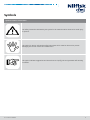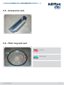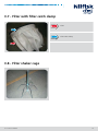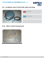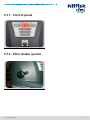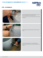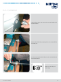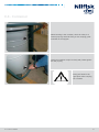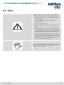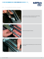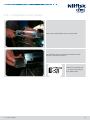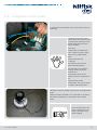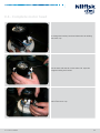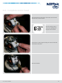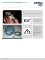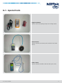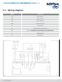
1
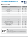
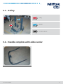
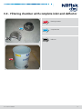
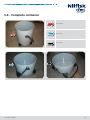
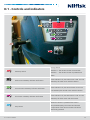
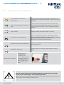
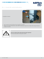
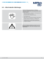
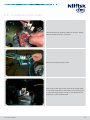
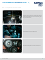
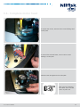
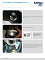
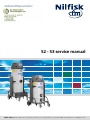
S2 - S3 service manual
Nilfisk-CFM S.p.A. Via Porrettana 1991 - 41059 Zocca (Modena) Italy - Tel. +39 059 9730000 - Fax +39 059 9730099 - www.nilfisk-cfm.com - [email protected]
Table of contents
Preface...........................................................................................................................................................................................page 3
Symbols.........................................................................................................................................................................................page 4
A Safety instructions...............................................................................................................................................................page 5
A.1 - Operator safety.............................................................................................................page 6
B Technical data.........................................................................................................................................................................page 9
B.1 - Technical data............................................................................................................. page 10
C Components......................................................................................................................................................................... page 11
C.1 - Trolley........................................................................................................................... page 12
C.2 - Handle complete with cable carrier...................................................................... page 12
C.3 - Filtering chamber with complete inlet and deflector....................................... page 13
C.4 - Complete container.................................................................................................. page 14
C.5 - Accessories rack......................................................................................................... page 15
C.6 - Filter ring and seal . .................................................................................................. page 16
C.7 - Filter with filter catch clamp .................................................................................. page 16
C.8 - Filter shaker cage ..................................................................................................... page 16
C.9 - Complete motor head.............................................................................page 17
C.10 - Motor head closing band......................................................................page 17
C.11 - Control panel........................................................................................page 18
C.12 - Filter shaker system...............................................................................page 18
D Vacuum cleaner operation............................................................................................................................................. page 19
D.1 - Controls and indicators. .......................................................................................... page 20
E Troubleshooting.................................................................................................................................................................. page 23
E.1 - Electrostatic discharge.............................................................................................. page 24
E.2 - Trolley............................................................................................................................ page 25
E.3 - Filtering chamber with complete inlet and deflector........................................ page 33
E.4 - Container..................................................................................................................... page 35
E.5 - Filter............................................................................................................................... page 38
E.6 - Complete motor head.............................................................................................. page 41
F Spare parts. ........................................................................................................................................................................... page 68
F.1 - Spare parts. .................................................................................................................. page 69
G Instruments.......................................................................................................................................................................... page 70
G.1 - Special instruments. ................................................................................................. page 71
H Wiring..................................................................................................................................................................................... page 72
H.1 - Wiring diagram.......................................................................................page 73
S2 - S3 service manual
2
Preface
This manual provides essential information required for repairing S2 - S3 series wet and dry vacuum cleaners.
When doing repairs, make sure you have a suitable workbench and the required electrical connection.
If particular anomalies are noticed during maintenance, please inform the customer who should have the user manual.
Appliance faults can be caused by several different factors. In this case refer to chapter E Troubleshooting.
For repairs, please refer to the list of spare parts indicating the positions of each component and the relevant sequence of assembly.
Read the Technical Service Bulletins carefully with the technical modifications performed after the manual was published.
The Technical Service Bulletins represent a supplement of the spare parts list until the next is published.
The manuals and bulletins must always be available during repairs. Other technical documents on the S2-S3 series may be required for repairs.
These documents should not be transferred to third parties.
ONLY USE ORIGINAL NILFISK-CFM SPARES!
S2 - S3 service manual
3
Symbols
Symbols used for instructions
The safety instructions indicated by this symbol in the manual must be observed to avoid injury
to persons.
This symbol is used to indicate the safety instructions which must be observed to prevent
damaging the vacuum cleaner and malfunctions.
This symbol indicates suggestions and instructions to simplify jobs and guarantee safe working
conditions.
S2 - S3 service manual
4
Safety instructions
A
A.1 - Operator safety
The repairs must only be carried out by personnel suitably trained for the job to do, or
a qualified electrician.
Before starting the vacuum cleaner, read these operating instructions carefully and keep them on hand for consultation.
The vacuum cleaner should only be used/serviced by people who are familiar with the way it works and who have been explicitly authorised and trained for the purpose.
Before using/servicing the vacuum cleaner, the operators must be informed, instructed and trained on how to use it and with
which substances it can be used, including the safe method for removing and disposing of the vacuumed material.
Use the vacuum cleaner in accordance with the laws in force in the country where it is used.
Besides the operating instructions and the laws in force in the country where the vacuum cleaner is used, the technical regulations for ensuring safe and correct operation must also be observed (Legislation concerning environmental protection and
safety at work, i.e. European Union Directive 89/391/EC and following).
Do not perform any operation that could jeopardize the safety of people, property and the environment.
Comply with the safety indications and prescriptions in this service manual.
Observe the provisions of the directives and national safety regulations on the sale of electrical appliances, in particular
EN60335-2-69- En.AA
Vacuum cleaners for dust harmful to health are classified according to the following dust classification:
1. L (low risk) suitable for separating dust with an exposure limit value of at least 1 mg/m3, depending on the volume occupied; retains at least 99% of the vacuumed particles (See EN60335-2-69, Enclosure A.A);
2. M (medium risk) suitable for separating dust with an exposure limit value of at least 0.1 mg/m3, depending on the volume
occupied; retains at least 99.9% of the vacuumed particles (See EN60335-2-69, Enclosure A.A);
3. H (high risk) for separating all dust with an exposure limit value lower than 0.1 mg/m3, depending on the occupied volume, including carcinogenic and pathogenic dusts such as asbestos. Class H14 Hepa filter in accordance with standard EN
1822; retains at least 99.995% of vacuumed particles (See EN60335-2-69, Enclosure A.A).
S2 - S3 service manual
6
A.1 - Operator safety
Class L-M vacuum cleaners are identified by labels with pictograms of the following meaning.
.
This vacuum cleaner contains dust hazardous for the health.
Only authorised personnel wearing suitable personal protective
equipment should empty and service the vacuum cleaner, including
removing the means used to vacuum the dust. Do not use without
the complete filter system in place.
Class H vacuum cleaners are identified by a label with the following text.
S2 - S3 service manual
7
A.1 - Operator safety
Check the place of work and substances tolerated for the vacuum cleaner suitable for liquids.
WARNING - DANGER !
In the case of electrical vacuum cleaners/instruments connected to the vacuum cleaner,
always refer to the user manual and safety instructions.
WARNING - DANGER !
Take care not to raise dust during maintenance operations. Wear a P3 protective mask.
S2 - S3 service manual
8
Technical specifications
B
B.1 - Technical data
PARAMETER
UNIT OF MEASURE
S2
L,M,H
S3
L,M,H
Voltage / frequency
V/Hz
230/5060
230/5060
Power rating
kW
2
3
Power rating (EN 60335-2-69)
kW
1.8
2.6
Max. weight
kg
67
73
Noise level (EN 60335-2-69)
dB(A)
70
71
Protection
IP
44
44
Insulation
Class
I
I
Capacity
L
40
50 - 100
Dust bag capacity (versions M - H)
L
32
32
Inlet
mm
Ø 70
Ø 70
Max vacuum
hPa
211
211
Maximum air flow without hose and reductions
L/min’
5500
8070
Maximum air flow (3 m Ø 50 mm hose)
L/min’
4720
6500
Hoses allowed for “L” and “standard” classes
mm
Ø 70
Ø 70
Hoses allowed for “M” and “H” classes
mm
Ø 50
Ø 50
Primary filter surface (L-M)
m2
1.95
1.95
Upstream absolute filter surface
m2
3.5
3.5
Absolute filter efficiency according to MPPS method (EN 1822)
%
99.995
(H14)
99.995
(H14)
Note:
•Storage conditions: T :
-10 +40 °C - Humidity: ≤ 85%
•Operating conditions: Maximum altitude 800 m (up to 2,000 m with reduced performances)
T : -10 +40 °C - Humidity: ≤ 85%
S2 - S3 service manual
10
Components
C
C.1 - Trolley
Trolley
Upright
Accessory support
C.2 - Handle complete with cable carrier
S2 - S3 service manual
12
C.3 - Filtering chamber with complete inlet and deflector
Filtering chamber
Complete inlet
Deflector
S2 - S3 service manual
13
C.4 - Complete container
100 L container
50 L container
40 L container
S2 - S3 service manual
14
C.5 - Accessories rack
C.6 - Filter ring and seal
Filter ring
Filter ring seal
S2 - S3 service manual
15
C.7 - Filter with filter catch clamp
Filter
Filter catch clamp
C.8 - Filter shaker cage
S2 - S3 service manual
16
C.9 - Complete motor head with cable and plug
Motor head
Cable and plug
C.10 - Motor head closing band
S2 - S3 service manual
17
C.11 - Control panel
C.12 - Filter shaker system
S2 - S3 service manual
18
Vacuum cleaner operation
D
D.1 - Controls and indicators
2-way selector
Start/stop switch
Position 0 - The vacuum cleaner is turned OFF
Position 1 - The vacuum cleaner is powered and
starts
Main motor Start/Stop indicator and button
Second motor Start/Stop indicator and button
Third motor Start/Stop indicator and button
If the indicator is lit, the main motor is ON. You can
start/stop the main motor with this button.
If the indicator is lit, the second motor is ON. You
can start/stop the second motor with this button.
If the indicator is lit, the third motor is ON. You can
start/stop the third motor with this button.
When this button is pressed all the motors
Stop button
stop simultaneously. The motors and internal
components of the vacuum cleaner will still be
electrically powered.
S2 - S3 service manual
20
D.1 - Controls and indicators
Low compressor pressure alarm
indicator (red)
Max. vacuumed material level indicator
(red)
If lit, this stops vacuuming and indicates an anomaly in the
pressure of the compressor (if installed). Check the compressor
is working.
If lit, this stops vacuuming and indicates the maximum level
of the vacuumed material has been reached in the container,
if the level control for liquids or solids is installed. Empty the
container.
Power indicator
Indicates whether the vacuum cleaner is powered.
Primary filter indicator (green/red)
Green - Indicates the primary filter is functioning properly.
Red - Indicates the primary filter is blocked. This means the air
speed in the suction tube is less than 20 m/s.
Stop the vacuum cleaner and clean the filter.
Absolute filter indicator (if installed-red)
Indicates the primary filter is blocked. Stop the vacuum cleaner
and change the filter.
Manual filter shaker knob
Lets you clean the primary filter using manual mechanical
action.
Shaking the primary filter
Depending on the
quantity of dust
vacuumed, if the
indicator turns red, turn
the vacuum cleaner off
and shake the primary
filter using the knob on
the side of the motor
head.
Stop the vacuum cleaner before shaking the filter. Do not shake the filter with the
vacuum cleaner functioning, as this could damage the filter.
Wait to let the dust to settle before restarting the vacuum cleaner. If the indicator is still red even
after the filter has been shaken, change the filter.
S2 - S3 service manual
21
D.1 - Controls and indicators
Emptying the container
•
We recommend cleaning the filter before emptying the container.
•
Release the container with the lever, then remove it and empty it. Replace the container after having checked the
condition of the seal.
Stop the vacuum cleaner before performing this operation.
Let the dust settle before removing the container.
S2 - S3 service manual
22
Troubleshooting
E
E.1 - Electrostatic discharge
Take the following precautions to discharge
electrostatic charges before doing any repairs on the
electrical circuits:
•
Touch the protective conductor to discharge any static
electricity charge in your body;
•
If possible, wear an antistatic bracelet;
•
Use antistatic mats;
•
Never touch a circuit board or electronic components,
always hold them with plastic or insulated tools;
•
Transport electronic components in conductive
packaging (special packs to discharge electrostatic
charges for example).
Before proceeding with these operations, turn off
the vacuum cleaner and remove the plug from the
power socket.
S2 - S3 service manual
24
E.2 - Trolley
Unscrew the 4 screws fixing the upright side panel by hand
or with a screwer.
The screws in the front are a different length.
The longer screws must be used near the reinforcing
spacer in the side-panel.
Do not swap screws
S2 - S3 service manual
25
E.2 - Trolley
Remove the side-panel. View of the upright.
Use a hex-head wrench to loosen the top screw holding
the side bracket.
Loosen the bottom screw too.
S2 - S3 service manual
26
E.2 - Trolley
The 2 side brackets have 4 hexagonal press-fit inserts.
Remove the 4 screws holding the 2 side brackets, turn the
filter chamber and pull it out of the 2 trolley uprights.
Take care when removing
the 4 screws. Hold the filter
chamber firmly
Proceed by unscrewing the handle with the cable carrier.
Use a hex-head wrench to tighten the 2 screws on each
side of the handle.
S2 - S3 service manual
27
E.2 - Trolley
Use a hex-head wrench.
Take care when removing
the 4 screws. Always hold
the handle firmly.
To remove and change the cable carrier, unscrew the 6
screws holding it on the handle.
Make sure the cable carrier is facing upwards.
S2 - S3 service manual
28
E.2 - Trolley
To remove and replace the plastic retainer of the
accessories support, unscrew the screw in the centre.
To remove and change the accessories support, unscrew
the 2 screws holding it on the upright with a hex-head
wrench.
Fit the accessories supports facing the right way.
This is important also in
order to connect the grip
properly.
S2 - S3 service manual
29
E.2 - Trolley
To remove and replace the container coupling bracket,
unscrew the bolts with a hex-head wrench.
Make sure you replace
the brackets in the right
position.
To remove and replace the whole upright, unscrew the 2
bolts holding it on the trolley.
To remove and replace the fixed wheels, unscrew the
nylock nuts with a wench.
Make sure the bolts are
tight after changing the
wheels. The wheel should
turn freely.
S2 - S3 service manual
30
E.2 - Trolley
To remove and replace the accessories rack, unscrew the
bolts under the front of the trolley.
Use a suitable hex-head wrench.
Remove the protective plug to remove the castors.
S2 - S3 service manual
31
E.2 - Trolley
Use a suitable hex-head wrench.
Make sure the bolts are
tight after changing the
wheels.
Block the trolley in place with the brakes to make changing
the wheels easier.
The brake should only be
activated and deactivated
with the feet. Never use
your hands.
S2 - S3 service manual
32
E.3 - Filtering chamber with complete inlet and deflector
The roundhead screws must have a washer and be
tightened down correctly to prevent air leaks (vacuum
loss).
Use roundhead screws to
prevent sharp parts tearing or
damaging the filter fabric.
The deflector must be turned to the correct position
(towards the container below).
Do not fit the deflector facing
upwards.
Make sure the tongue that guarantees earth continuity
between the motor head the filtering chamber is always
fitted.
S2 - S3 service manual
33
E.3 - Filtering chamber with complete inlet and deflector
The seal must be fitted correctly in the side groove and
bonded in place with suitable glue (such as Bostik). Also
make sure the joint of the 2 parts is bonded properly.
If it isn’t fixed correctly, this
could lead to air leaks (vacuum
loss).
Do not fit the seal under too
much tension in relation to its
length of 1.5 m.
If the seal leaks:
•
Loosen the four screws holding the brackets on the uprights of the frame;
•
Lower the filtering chamber and tighten the screws again with the half released (container lever in the middle of its
travel) container pressed down on the seal;
•
The gasket must be replaced if it is torn, cut, etc.
•
Replace the seal if the degree of tightness is still not optimal.
The complete inlet must be installed correctly (with the
seal between the inlet and the filtering chamber and the
screws tightened properly).
If the screws aren’t tightened
properly, this could cause air
leaks (vacuum loss).
S2 - S3 service manual
34
E.4 - Container
To remove and replace the container wheels, remove the
plastic wheel guard using a suitable wrench.
The plastic support fits on the wheel bracket with 2 studs
on the side.
Unscrew the bolt in the wheel bracket using a hex-head
wrench.
To remove the release lever, use an Allen wrench to
unscrew the hex-head screws in the bush welded on the
container.
S2 - S3 service manual
35
E.4 - Container
Unscrew the screws, then remove the normal washers and
serrated washer.
Remove the whole lever, opening it out so it comes off the
2 welded pins.
To remove and replace the roller pin, use a screwdriver and
a hex-head wrench.
Make sure the roller pin
slides freely.
S2 - S3 service manual
36
E.4 - Container
When inserting in the container, check the roller pin is
inserted properly and slides freely on the coupling guide
mounted on the uprights.
Check the container couples correctly and presses against
the seal properly.
Keep your hands in the
right place when coupling
the container.
S2 - S3 service manual
37
E.5 - Filter
When the vacuum cleaner is used to vacuum hazardous
substances, the filters become contaminated, therefore:
•
Work with care and avoid spilling the vacuumed dust
and/or material;_
•
Place the disassembled and/or replaced filter in a
sealed plastic bag;
•
Close the bag hermetically;
•
Dispose of the filter in accordance with the laws in
force;
•
Filter replacement is a serious matter. The filter must
be replaced with one that has the same characteristics
(surface area and class); otherwise the vacuum cleaner
may malfunction and operate in unsafe conditions;
•
Check the vacuum cleaner class (L-M-H). Take care not
to raise dust when this operation is carried out. Wear a
P3 mask and other protective clothing plus protective
gloves (PPE) suitable for the hazardous nature of the
dust collected. Refer to the laws in force.
The filter must be changed if it is blocked, torn or cannot
guarantee high filtering efficiency. If shaking the filter isn’t
enough, it must be replaced.
S2 - S3 service manual
38
E.5 - Filter
When the complete filter kit has been removed from the
motor head, unscrew the clamp and remove the filter ring.
Turn the filter upside down. Cut the plastic ties and detach
the cage from the filter.
Fit the filter catch and the seal ring of the old filter on the
new one (replace if necessary). Insert the cage and tie it to
the filter using the ties (one every 2 bags) at the bottom of
the filter.
Don’t cut the excess off the tie
after pulling tight. This prevents
leaving sharp parts that could
damage the filter during normal
use and shaking.
Before positioning the motor head on the filter, arrange
the filter properly in the filter chamber.
Position the filter with the
bags completely extended to
guarantee optimal filtering.
S2 - S3 service manual
39
E.5 - Filter
After having positioned the motor head, check the filter
shaker rod moves correctly. The lever must be in the central
position and the travel must be free in both directions
without any particular difficulties.
If the movement isn’t right, lift the motor head and align
the filter. Try shaking again.
When shaking, hold the
knob correctly and take
care not to trap your
fingers.
S2 - S3 service manual
40
E.6 - Complete motor head
Open the closing band to remove the motor head from the
filtering chamber.
Open it out completely to remove it from the side link.
Take care not to injure your
hands with the snap catch.
Remove the whole motor head, lifting it our of the frame,
making sure you have a firm grip on it. Use the handles on
the sides of the motor head.
Before closing the band
again, centre the motor
head properly on the
filtering chamber. The
motor head flange must
be centred and positioned
perfectly on the seal of the
filter ring.
S2 - S3 service manual
41
E.6 - Complete motor head
Remove the motor head, pulling out the hex-pin cage from
the bush.
When replacing the motor head,
make sure the cage is inserted
correctly in the bush and the filter
bags are extended properly with
no twists.
It may be easier to assemble the
cage first on the motor head and
then position both on the filtering
chamber. In this case, take great
care not to trap your fingers.
Proceed by unscrewing the filter shaker knob.
Unscrew the 4 screws positioned every 90° around the
motor head.
S2 - S3 service manual
42
E.6 - Complete motor head
Remove also the screw under the main switch.
All the screws are the same length, except the one under
the main switch which is much longer.
Now the motor cover can be removed from the base. Take
particular care with the main switch. Pull it out, removing
also the control panel.
S2 - S3 service manual
43
E.6 - Complete motor head
Hold the bottom edge to remove the motor cover. Pull the
cover out, then up.
Pull the motor cover off, taking
care not to damage the control
panel.
Turn the motor cover over and unscrew the screws inside.
Remove the motor cover from the top cover.
S2 - S3 service manual
44
E.6 - Complete motor head
Remove the sponge in the specific housing of the motor
cover.
If you have to bond parts of the sponge that have come
unstuck, clean the surfaces thoroughly and only then stick
the sound-proofing sponge back on using a few drops of
liquid glue.
In any case we recommend
using original spare parts,
which include pre-bonded
sponges.
Remove the round sponge in the filter shaker lever.
S2 - S3 service manual
45
E.6 - Complete motor head
Remove the sponge from its seat.
The 4 recessed nuts should be fitted in the 4 holes every
90°.
Pull the press-fit pipes off the connectors.
During assembly make
sure they fit properly in
the connectors and that
the yellow and blue colour
codes are respected.
Pull the pipes off the internal clips.
S2 - S3 service manual
46
E.6 - Complete motor head
Pass the cables and tubes through the right holes.
Disconnect the motors from the electronic board, pulling
the Faston terminals off connectors M1-M2-M3.
Connector M3 isn’t used in
2 motor heads.
Pull the 3 Faston terminals of the motors off connectors L
on the terminal board. Pull also the Faston terminal of the
blue cable off connector N on the terminal board.
When wiring, make sure
the cables are laid out
properly and hold them in
place with appropriate ties.
S2 - S3 service manual
47
E.6 - Complete motor head
The bridge between L and N is wired in only on heads with
3 motors.
To remove the board, unscrew the hex-head screw at the
bottom.
Unscrew the screws at the sides of the board.
S2 - S3 service manual
48
E.6 - Complete motor head
Unscrew them both.
Remove the board, pulling it upwards.
Unscrew the screws and remove the power cable of the
main switch.
When wiring, make sure
the Faston terminals
are firmly fixed on the
connectors and the
terminals are tight on the
terminal board.
S2 - S3 service manual
49
E.6 - Complete motor head
Remove also the cables going to the terminal board and
those connecting the switch to the components of the
electronic board.
Pull off the green connector and connect the blue and
brown wires to the board.
Pull off also the Faston terminals on the side of connectors
M1-M2-M3.
S2 - S3 service manual
50
E.6 - Complete motor head
Always make sure the Faston terminals have been crimped
correctly.
Remove the ties holding the cables on the motor mounting
plate to make wiring easier.
Before removing the board completely from the motor
head, check all the connectors have been disconnected.
S2 - S3 service manual
51
E.6 - Complete motor head
Don’t disconnect the wires by pulling on the wire, always
hold the Faston terminal or connector.
Remove the whole electronic board.
Each corner of the motor stator pack has an output cable.
2 blue cables connected to the brushes of the same motor,
2 connected respectively to connector M1-M2-M3 of the
board and 1 to the terminal board.
S2 - S3 service manual
52
E.6 - Complete motor head
Proceed by removing the motor mounting plate. Unscrew
all the hex-head M6 screws on the motor mounting plate
using a hex-head wrench .
Hold the plate firmly on both sides and lift.
The plates lifts away with the 3 motors mounted on it.
S2 - S3 service manual
53
E.6 - Complete motor head
To replace the motors, unscrew the 2 screws holding them
on the plate.
To remove the terminal board, screw in the 2 screws
holding it on the plate.
Pull the motor through the hole in the plate.
Take care not to damage
the cables. Turn or tilt the
motor to pull it out.
S2 - S3 service manual
54
E.6 - Complete motor head
Once removed, the motor has 2 seals (top and bottom) on
the fan.
Remove the 2 seals from the fan.
When assembling, make
sure the seals are in an
good condition (replace
if necessary) and fitted
correctly.
Remove the 4 baseplates with the butterfly vacuum cutoff
valves inside from their housing in the motor mount of the
head. The 3 spacers of the butterfly vacuum cutoff valves
must face upwards as shown in the photo.
S2 - S3 service manual
55
E.6 - Complete motor head
Remove the base of the motor cover, unscrewing the 3
screws at the base.
The 3 screws are the same length.
Proceed by unscrewing the M8 screws on the motor
mount to remove the 2 spacers and the filter shaker.
On heads with 2 motors (S2) remove also the baseplate
closing the hole of the 3rd motor.
S2 - S3 service manual
56
E.6 - Complete motor head
Turn the motor head over and remove the 2 spacers.
Turn the head over again and loosen the central bolt
holding the filter shaker shaft.
Hold the shaft while you unscrew the bolt.
When fixing the shaft with
the central screw, always
insert the serrated washer
to prevent it slipping when
shaking.
S2 - S3 service manual
57
E.6 - Complete motor head
Remove the filter shaker shaft, tilting it and moving it
upwards. Remove also the complete filter shaker.
During assembly, make
sure the square-seat shaft
is correctly inserted and the
round lever slides correctly
in the slot of the filter
shaker shaft.
Remove the base of the motor cover from the motor
mount.
Turn the motor mount and pull the filer shaker shaft out of
the central bush.
S2 - S3 service manual
58
E.6 - Complete motor head
Make sure the pipes are in the right position. Yellow on
the inner D.6x1/8” fitting, blue on the external D.6x M5
fitting.
The pipes are press-fit in the fittings.
Use Locktite on the nuts of
the air fittings.
Unscrew the 3 screws holding the central bush on the
motor mount.
S2 - S3 service manual
59
E.6 - Complete motor head
Remove the bush and seal.
To dismantle the filter shaker system, unscrew the 4 screws
holding it on the plate.
Remove the filter shaker.
S2 - S3 service manual
60
E.6 - Complete motor head
To remove the 2 bumpers, unscrew the 2 bolts holding
them on the frame with a hex-head wrench.
Remove the bumpers and washer.
To remove the filter shaker shaft, pull it out from one side
of the bush.
S2 - S3 service manual
61
E.6 - Complete motor head
Then remove the shaft also from the other bush.
The 2 bushes must be press-fit and inserted from the
outside in the holes on the box.
Make sure the bushes are
a correct fit by sliding the
filter shaker shaft.
S2 - S3 service manual
62
E.6 - Complete motor head
To connect the components of the control panel, see part
H (Wiring).
Check the connection of the
power cable. The terminals must
only clamp the metal tips of the
Faston terminals and not the
plastic insulation.
Also check:
All the Faston terminals have
been crimped correctly. Check
they can’t be pulled off the
wires.
All the earth wires are
connected.
The buttons must turn the
system ON/OFF properly.
The indicators must function
properly (power ON, filters
blocked, etc.).
The pressure switch in the
electronic board is supplied preset.
If the electronic board
malfunctions, don’t try to repair
it. Replace the whole board.
The power wires are already connected to the single-phase
motor.
Make sure Faston terminal 6.3 is connected to the board,
and Faston terminal 4.8 is connected to the terminal
board.
If the vacuum motors are
noisy or produce a lot of
sparks, the brushes may
need changing.
S2 - S3 service manual
63
E.6 - Complete motor head
To change the brushes, bend and release the tab holding
the motor cap.
Do the same with the tab on the other side. Open the
tongues holding the brushes.
Pull off the motor cap.
S2 - S3 service manual
64
E.6 - Complete motor head
Pull downwards and disconnect the Faston terminal with
the blue wire on the brushes.
Pull off carefully, taking
care not to damage the
tongue of the brushes.
Press down on the tongue blocking the motor brush with
a flat blade screwdriver.
Pull out the brush.
S2 - S3 service manual
65
E.6 - Complete motor head
Insert a new brush, making sure it is facing the right way.
Make sure the tongue holds
it in place properly, so it
can’t come out of its seat.
Only replace the electric
power cable with one of the
same type as the original
H07 RN-F. The same rule
applies if an extension is
used. All the sockets, plugs
and commutators must
have the same IP protection
degree as the vacuum
cleaner, as indicated on the
data plate.
S2 - S3 service manual
66
E.6 - Complete motor head
WARNING - DANGER !
After having repaired the motor head,
S2 - S3 service manual
•
before plugging the vacuum cleaner into the electrical
mains, make sure the voltage rating indicated on the
data plate corresponds to that of the electrical mains;
•
plug the vacuum cleaner into a properly earthed
socket;
•
make sure the vacuum cleaner is turned off;
•
if the plug has been changed, make sure the cable is
in a perfect condition (damaged cables can cause
electric shocks).
•
The vacuum cleaner’s power socket must be protected
by a differential circuit-breaker with surge current
limitation that cuts off the power supply when the
current discharged to earth exceeds 30 mA for 30 ms
or an equivalent protection circuit.
•
If there are electrostatic currents on the vacuum
cleaner, the earth is probably not connected or
in a poor condition. In this case check the earth
connections, in particular those of the inlet fittings;
the hose must be antistatic.
67
Spare parts
F
F.1 - Spare parts
Use the current spare part list.
S2 - S3 service manual
69
Tools
G
G.1 - Special tools
Digital multimeter
Used to check the amperage (Amps) and voltage (Volts).
Vacuum meter
Used to measure the vacuum power with the inlet closed
(mbar).
Airflow meter
Used to measure the airflow with the inlet open (m3/h).
S2 - S3 service manual
71
Wiring
H
H.1 - Wiring diagram
ABBREV.
COMPONENT
M1
Motor switch 1
M2
Motor switch 2
M3
Motor switch 3
MSE
Filter shaker motor
CL1
Level control
PR1
Compressed air pressure switch
HA1
Alarm - air speed in the suction tube is less than 20 m/s
C1
Antidisturb filter
Q1
Main switch
S2 - S3 service manual
73