1
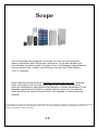
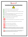
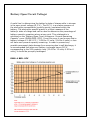
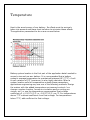
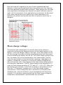
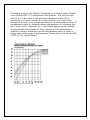
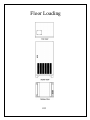
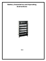
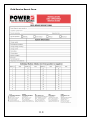
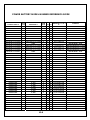
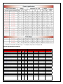
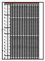
Power Battery Company, Inc.
Field Service Manual
Valve Regulated Lead Acid (VRLA) Battery
Field Service and Application Manual
First Edition
February 2007
Table of Contents
1.0
Scope
2.0
Safety
3.0
Storage Requirements
4.0
Ventilation
5.0
Temperature
6.0
Floor Loading
7.0
Neutralizing Spilled Acid
8.0
Visual inspection and Open Circuit Voltage (OCV) Measurement
9.0
Safety Procedures and Tool List for System Maintenance
10.0
Battery Installation and Operating Instructions
11.0
Field Service Report Form
12.0
Power Battery Model Number Reference Guide
13.0
Contact Information
Scope
This manual has been designed to provide the user with some specific
battery application and field service information. It has been divided into
nine sections by subject matter for ease of use. By following these guidelines
one can expect safe, reliable, cost-effective service from Power Battery
V.R.L.A. batteries.
Power Battery believes that with qualified experienced personnel, following
these instructions step-by-step, adopting normal safety precautions for
electrical installations, paying particular attention to those emphasized in the
attached specification and with the safety features built into the cabinets
there should be no reason for personnel to be exposed to undue electrical
hazards.
This information is presented in good faith, but no additional warranty is expressed or implied. In as much as any assistance furnished
by Power Battery Company. Inc. with reference to the proper use of its products without charge, power Battery Company, Inc.
assumes no obligation or liability therefore.
1.0
SAFETY
General Safety Rules for Handling Power Battery Company, Inc. Batteries
DO use qualified personnel only for battery handling and maintenance.
DO follow all Power Battery and charger maintenance instructions.
DO wear protective equipment (face shield, goggles, gloves) when working with or around
battery systems.
DO make sure that all charging/discharging circuitry is completely disconnected from the
battery system before making or breaking any connections.
DO check with Power Battery before making any design changes to the battery system.
DO use proper lifting techniques when working with the batteries.
DO NOT lift any battery by the battery terminals.
DO NOT allow tools or unconnected cables to rest on top of the batteries or touch the battery
terminals.
DO NOT use power tools that can develop more torque than the torque specified for
connections.
DO NOT use any chemical cleaners to clean the batteries.
DO NOT remove vent caps or add anything to the batteries.
DO NOT smoke or carry open flames near any battery or system.
DO NOT approach any energized battery system that shows signs of severe over charging or
over discharging (severe swelling, cover deformation, vent caps missing). Disconnect and
isolate the battery system from all charging and discharging circuitry before approaching the
system.
DO NOT circumvent any device installed by Power Battery or the Charger Manufacturer for
the purpose of protecting the battery system. These devices include: Fuses and Circuit
Breakers, Disconnects, Switches and any other protection devices.
2.0
Storage Requirements
3.0
Storage
All lead-acid batteries will self-discharge when allowed to stand on open
circuit. This self-discharge is due to "Local Action" caused by dissimilar
metals (positive vs. negative plates) used within the cell's construction.
The result of the self-discharge is loss of cell open circuit voltage,
consequently loss of capacity. If allowed to progress beyond the normal
limits, excessive plate sulfation may occur causing permanent loss of
capacity and premature battery failure.
These batteries have been designed to minimize the effects with the use
of the purest plate materials available. This has resulted in a reduction of
the self-discharge rate to approximately one-fifth of a conventional lead
acid battery. The rate of self-discharge will also be dependent upon the
battery's storage temperature. Lower storage temperatures will reduce
the self-discharge rate; higher temperatures will increase the rate. A cool,
dry area is the recommended environment in which batteries should be
stored. They should also be placed away from any heat sources including
heaters, steam pipes, equipment or in direct sunlight. The table below
represents the maximum allowable storage time at various battery
storage temperatures.
Storage parameters
Ambient Temperatures Typical storage time
0°F - 32°F
12 months
33°F - 65°F
9 months
66°F - 90°F
6 months
91°F - 105°F
3 months
106°F - 120°F
1 1/2 months
Battery Open Circuit Voltage:
A useful tool in determining the battery's state of charge while in storage
is the open circuit voltage (O.C.V.). The O.C.V. is a relative measure of
the electrolyte concentration (specific gravity) contained within the
battery. The electrolyte specific gravity is a direct measure of the
battery's state of charge and can be used to determine the percentage of
battery capacity remaining at any given point. This relationship is
exhibited on the "Battery Open Circuit Voltage vs. Percent Remaining
Capacity" curve (DWG# BSD- OCV). From this curve it can be seen that a
battery voltage of 1.98 V.P.C. (11.88 for 12 volts, 5.94 for 6 volts) or less
will have zero percent capacity remaining. In order to prevent any
possible permanent plate damage from occurring due to self-discharge, it
is recommended that when any battery in storage has an O.C.V.
corresponding to the 50% capacity level (12.40 for 12 volts, 6.20 for 6
volts), it should be promptly recharged.
DWG. # BSD- OCV
Notes
Using these parameters, one can take advantage of the longest possible
storage durations without subjecting the battery to any potential harm
caused by the delirious effects of prolonged self- discharge. The open
circuit voltage (O.C.V.) can also be useful in approximating the remaining
storage time available before the batteries reach the minimum O.C.V.
(12.40V / 12V or 6.20V / 6V) before recharge. A curve has been provided
to show the relationship of "Battery O.C.V. vs. Percent Storage Time
Remaining" (DWG. # BSD- OCV). To use this curve take the O.C.V. of the
battery and locate the point on the curve which intersects with the
percent remaining storage time. This percentage is then multiplied by the
storage time and temperature parameters given earlier to calculate the
approximate storage time remaining before required recharge. It should
be noted that the battery's O.C.V has some limitations on its accuracy.
The percent capacity remaining is within -10% or +10% if the battery has
been on charge or discharge within the last 24 hours. After a battery has
remained on open circuit for a minimum of 72 hours the accuracy
increases to -2.5% or +2.5%
The battery O.C.V. can also be used in approximating the state of charge
after a discharge using the same parameters as described above.
However, it should be noted that this does not apply for the percentage of
remaining storage time curve as all batteries should be recharged
immediately after a discharge. All batteries should be recharged using a
constant voltage of 2.27 - 2.30 V.P.C., at 77°F, for a minimum of 24
hours or until the float current stabilizes for 3 consecutive hourly
readings. Battery carton date coding All battery cartons are date coded
with a recommended recharge data. The date code (month / year) has
been calculated for "normal” storage temperature conditions (66°F 90°F) and dated 6 months from the battery's last full charge. The
battery's O.C.V. should continue to be checked at frequencies described
earlier to give a true indication of when a battery will require a recharge.
Battery terminal date coding consists of the month and year date of
manufacture located on the negative battery terminal unless noted
otherwise.
Due to the natural self-discharge of the batteries, many of the storage
parameters discussed earlier would apply when "shutting down" and
storing a battery system. As before, the battery's O.C.V. is a useful tool in
determining when a recharge would be required. All batteries placed in
storage should be fully charged before shutting down and disconnecting
from the system.
The batteries may also need to be relocated if the environment is not
suitable for storage (refer to storage parameters). When shutting down a
battery system that has been in use, some additional considerations will
need to be made. First, and foremost, the batteries must be fully charged
before the equipment is shutdown. Second, the battery must be
disconnected (via disconnected, breaker, etc.) completely from the
equipment circuitry. One must insure that all possible loads are also
disconnected so that the batteries are not unknowingly discharging during
the shutdown period. Examples of other small loads may be shunted
devices or other small resistive loads tied into the circuit. As an additional
safety measure one of the battery fuses or intercell connections can be
removed.
Caution: Be sure battery system is disconnected from circuit before
removal of any intercell connectors.
Finally, record the date when the system was shut down and include this
with the regularly scheduled maintenance records for future use. It may
also be advisable to place a recharge date directly on the batteries as an
additional visual aid to indicate when a recharge would be required.
Ventilation
4.0
Ventilation
When Power Battery series of batteries are charged at constant potentials
below 2.37 VPC at temperatures up to 92ºF, (33.33ºC) and below 2.25
VPC up to 107ºF, (41.67ºC) 100% of the gases produced are recombined
internally so that no gas is evolved. If the batteries are charged at higher
voltages or temperatures, small amounts of gas may be evolved.
Recombination efficiency is about 90% at 2.5 VPC @ 107ºF (41.67ºC).
Power Battery VRLA batteries internally recombine all gasses generated
within the batteries if they are charged or maintained on float within the
recommended charge conditions. If the batteries are charged at voltages
above 2.37 VPC (14.22 volts for 12 volt batteries) small amounts of gas
may be evolved, particularly if the batteries are above ordinary
temperature.
A typical UPS battery installation uses battery cabinets with an internal
volume of 56 cubic feet (Power CR4). Such cabinets usually contain 40
batteries occupying 23 cubic feet and electronic gear occupying 1 cubic
foot leaving 32 cubic feet of free air space. The cabinet has ventilations
slots with a total open area of 0.32 square feet. Hydrogen will leave the
cabinet both by diffusion through the ventilation slots (and other
openings) and by convection.
Calculations based on the known diffusivity of hydrogen show that a
maximum equilibrium concentration of 0.062% hydrogen will be reached
within the CR4 cabinet when the batteries are charged at 2.5 VPC at 77ºF
(25ºC) without any convection.
If the batteries are charged under the extreme condition of 2.5 VPC at
107ºF (41.67ºC) about 80ml per hour will escape from each battery so
that diffusion alone will result from each battery so that diffusion alone
will result in a maximum cabinet concentration of 0.23% hydrogen. Since
some convection will occur, the actual hydrogen concentrations will be
well below these calculated equilibrium concentrations.
The calculation of Gas Produced and Recombination Efficiency is not
strictly correct since some small current will be accepted by all batteries
without the production of gas.
The error is very small and, since the calculation provides a convenient
way to compare recombinant batteries of different design, many battery
researchers have used the method.
The data shown in the table has been plotted on the attached charts that
show Gas Recombination Efficiency and Actual Gas Evolution as a function
of Cell Voltage.
The minimum concentration of hydrogen in air that is required for
combustion is 4.1%. The current IEEE standard for the maximum safe
concentration of hydrogen in air is 2%. The maximum, diffusion limited,
equilibrium concentration of 0.23% obtained at 2.5 VPC and 107ºF
(41.67ºC) is about 10% of this.
If charging is done under the more normal conditions of 2.37 VPC
hydrogen concentration within the cabinet will not exceed 0.02% and will
approach the natural atmospheric hydrogen concentration of 0.01%.
If Power Battery VRLA batteries are operated within the recommended
guidelines and if cabinet ventilation slots are not impeded, there is no
possibility of reaching dangerous concentrations of hydrogen within the
battery cabinet.
Temperature
5.0
Temperature
Heat is the worst enemy of any battery. Its effects must be seriously
taken into account and steps must be taken to minimize these effects.
The application parameters to do so are covered below.
Battery system location is the first part of the application detail needed to
properly size and use any battery. It is recommended that a battery
system's average temperature be maintained between 68° (77°F). A cellto-cell variation of 5°F (maximum) is also highly desirable. When a
system location calls for temperatures outside these parameters,
applications engineering may use one of the following methods. Design
the system with the added temperature environment controls ( ex:
change o system location, forced air circulation and/or cooling provisions, etc.) or use the temperature compensation float voltage
coefficient of + 0.0017 V.P.C. or -0.0017 V.P.C. per °F. For temperatures
above 77°F subtract coefficient from float voltage. For temperatures
below 77°F, add coefficient to float voltage.
A battery system's discharge capacity:
A battery system's discharge capacity is directly related to the battery's
temperature. PRC Series batteries are rated 100% at 77°F. The
percentage of capacity available at a specific rate of discharge can be
taken directly from the "Percent Capacity VS. Temperature" curve (DWG#
BTD-377) enclosed. To use, one must first select the rate of discharge
closest to the actual rate the application calls for, then travel along the
curve to the expected operating temperature on the horizontal axis. Now,
find the point on the vertical axis that corresponds to the temperature
and rate curve selected. Multiply this percent capacity by the ampere or
wattage rate on the published discharge curves to arrive at the
temperature corrected discharge rate.
The designed float service life:
The designed float service life of Power Battery batteries is 10 years at
77°F using a 2.27 - 2.30 V.P.C temperature compensated float charge
voltage. The float service life is directly related to the application's
operating temperature. For temperatures above 77°F standard, grid
growth (corrosion) is accelerated and battery life is shortened. The actual
amount in which the life will be affected is given on the "Temperature
effects on long term float life" curve (DWG# BTD-277) enclosed. This
curve was derived from experimentation based on the developments by
the scientist E. Willihnganz in a paper presented in "Electrochemical
Technology", Oct, 1968. This paper titled "Accelerated Life Testing of
Stationary Batteries" describes the test procedures performed to obtain
the experimental data on battery float service life. This procedure is the
most widely accepted method of accelerated testing used today because
the primary cause of battery failure, grid growth (corrosion), has been
found to correspond with the failure mechanisms found in actual field
tests.
One final note with regards to the use of valve regulated lead acid
batteries is that most immobilized electrolyte systems are less forgiving
than the traditional flooded battery systems. These designs are such that
many application advantages are inherent but careful attention must be
paid to all the parameters of the application's environment. As discussed,
with proper maintenance and monitoring of these parameters, the
batteries will perform and provide the level of service in which they're
designed.
Float charge voltage:
The selection and maintenance of a specific float charge voltage is
essential to achieving the designed service life and rated capacity of the
battery. If the float charge voltage is too high, more float charge current
will flow through the battery causing accelerated grid growth (corrosion),
hence shortening the battery service life. If the float charge voltage is too
low, the battery will not be maintained in a full charge state. This will
cause the accumulation of the lead sulfate, resulting in degradation of
capacity, followed by a reduction in service life. Battery temperatures
play an important role in the selection of the float charge voltage used in
any stationary application. The PRC Series batteries are designed for 10
years full float charge operation @ 77°F and 2.27 - 2.30 V.P.C. When the
application's environment is such that the battery's temperature varies
from the 77°F standard, changes occur in the float charge voltage
requirements. These changes are due to variations in the battery selfdischarge rate, internal resistance, current acceptance and electrolyte
viscosity. It is therefore recommended that the float charge voltage be
temperature compensated to accommodate the variations.
Enclosed is a copy of the "Battery Temperature vs. Float Charge Voltage"
curve (DWG# BTD-177) developed for this purpose. This curve can be
used in one of two ways. If the average temperature profile of the
application is a known constant or is well controlled, the float charge
voltage can be set on the charger according to the compensation curve. If
the application calls for unknown battery temperatures or variations (ex:
day / night, winter / summer, ect.), the charger design can be modified
to automatically compensate for these variations. This modification is
relatively simple to accomplish, as the compensation factor is linear in
nature over a wide range of temperatures. Please refer to the curve DWG
# BTD-177 for further details.
Floor Loading
6.0
Location and Mounting
Mounting holes are provided on the cabinet for securing the cabinet to the
floor when necessary. If a multi-cabinet system was installed, consult the
inter-cabinet connection drawings, supplied with the system, for proper
positioning and spacing between each cabinet. Cabinets must be bolted to
the floor if UBC seismic zone and Underwriters Laboratories requirements
are to be met.
Cabinets may also have levelers, casters or both. When installed one or
both should have been adjusted properly by a qualified service person.
Some cabinets may not have levelers, casters or both; instead a floor
loading plate may have been installed for proper cabinet weight
distribution.
NEUTRALIZING SPILLED ACID
Sulfuric acid: Sulfuric acid is a strong corrosive. Contact with the acid can
cause severe burns to the skin and eyes. Ingestion of sulfuric acid will
cause gastro intestinal tract burns.
First aid •
•
•
Sulfuric acid: Skin contact: Flush with water for 15 minutes. Remove
contaminated clothing. Call physician if contact area is large, or if blisters
form.
Eye contact: Call physician immediately, flush with water until physician
arrives.
Ingestion: Call physician DO NOT INDUCE VOMITING. DO NOT GIVE
ANYTHING TO AN UNCONSCIOUS PERSON.
Spill or leak procedures: If sulfuric acid is spilled from a battery,
neutralize the acid with sodium bicarbonate (baking soda), sodium
carbonate (soda ash) or calcium oxide (lime). Flush the area, and dispose
of as hazardous waste.
7.0
Waste disposal method:
Spent lead acid batteries are disposed of using three (3) acceptable
methods: send the batteries to:
1. Licensed secondary lead smelters for recycling
2. Reputable battery handlers
3. Reputable scrap dealers.
If the user has to transport these batteries to the smelters, the user must
follow department of transportation (DOT) regulations. A copy of this
material safety data she et must be supplied to any scrap dealer or
secondary lead smelter. Follow applicable Federal, State, and Local
regulations.
Protection: Skin - rubber gloves, apron.
Respiratory: Protective equipment must be worn if the battery is cracked
or otherwise damaged. HEPA respirator should be worn during reclaim
operations, if the OSHAPEL is exceeded.
Eyes safety: Goggles, face shield.
Electrical safety: Due to the low internal resistance of Power Batteries and
high power density, high levels of short circuit current can be developed
across the battery terminals. Do not rest tools or cables on the battery.
Use insulated tools only. Follow any installation instructions and diagrams
when installing or maintaining battery systems.
VISUAL INSPECTION AND OPEN CIRCUIT VOLTAGE
(OCV) MEASUREMENT
8.0
Battery Inspection:
A detailed visual inspection of each battery should be performed.
Items to be checked are:
1. Signs of damage to the case, cover or terminals.
2. Staining of the case, terminals or surrounding areas.
3. Excessive swelling of battery case.
4. Evidence of melting or thermal damage to the case cover and terminal
post-seal.
5. The supporting cabinet, rack or tray should be checked confirming
that there is no physical damage or corrosion.
Cable Connections:
Care must be taken to insure that all cables within the cabinet(s) are
mechanically and electrically secure.
All connections should be retorqued annually to 5 IN-LB less than initial
values specified on the battery label.
For first time battery cable installation, connections should be torqued to
the stipulated value on the battery label located on the battery. In all
other cases, torque cable connections to 5 IN-LB less than the labeled
torque value.
The connections must be retorqued with a torque wrench. Using only a
wrench will cause strain on the terminal and internal battery connections
resulting in permanent battery damage.
The retorqing is necessary to insure good low resistance connections and
equal battery float voltage distribution. Loose connections can result in
high power drains and high terminal temperatures on discharge, resulting
in reduced capacity, possible personal injury and equipment damage.
Caution: DO NOT over-torque terminal connections. Excessive
pressure on the terminal will cause creep flow of lead, resulting in low
contact pressure, loose connections, and possible permanent damage to
the terminals.
SAFETY PROCEDURES AND TOOL LIST
NEEDED FOR SYSTEM MAINTENANCE
9.0
Protective Equipment:
1. Goggles and face shields.
2. Acid-resistant insulated gloves.
3. Protective aprons and overshoes.
4. Lifting devices of adequate capacity, when required.
5. All tools used during battery installation and system hook-up must be
insulated.
6. Use rubber mats on floor and over batteries when working on the
battery system connections.
Safety Procedures:
1. Inspect all lifting equipment for functional adequacy and to make sure
it is of sufficient capacity to lift the weight involved.
2. Prohibit smoking and open flame, and avoid arcing in the immediate
vicinity of the battery.
3. Ensure that adequate illumination requirements for inside the battery
system are met.
4. Always make sure that there is an unobstructed path from the battery
area to the exit.
5. Avoid static buildup by having personnel contact ground prior to
working on batteries.
6. Servicing of battery or batteries should be performed or supervised by
personnel knowledgeable of batteries and the required precautions.
Keep unauthorized personnel away from batteries.
7. When replacing batteries, use the same number and type specified on
the battery or drawing. The battery or batteries should be valveregulated lead acid type.
8. Caution – Do not dispose of battery or batteries in a fire. The battery
may explode.
9. Caution – Do not open or mutilate the battery or batteries. Released
electrolyte is harmful to the skin and eyes. It may be toxic.
10. Caution – A battery can present a risk of electrical shock and high
short circuit current. Observe proper precautions.
11. Proper disposal of battery or batteries is required. Refer to your local
codes for disposal requirements.
12. The following safety procedures shall be followed:
A. Remove watches, rings, and other metal objects.
B. Use tools with insolated handles.
C. Where rubber gloves and boots.
D. Do not lay tools or metal parts on top of batteries.
E. Disconnect charging source prior to connecting or disconnecting
battery terminals.
13. Determine if the battery is inadvertently grounded. If inadvertently
grounded, remove source of ground. Contact with any part of a
grounded battery can result in electrical shock. The likelihood of such
shocks will be reduced if such grounds are removed during
maintenance. This paragraph is applicable to a UPS and a remote
battery supply not having a grounded supply circuit.
Tool List needed for System Maintenance:
1. Digital Voltmeter: 3-1/2 digit minimum 0.25% accuracy, rated 600
V.D.C. minimum. Due to the close tolerances needed for battery
maintenance (typically 20-40 MV on a 20V scale) analog meters are
not recommended. The voltmeter should be checked and calibrated at
yearly intervals.
2. Thermometer: Thermocouple contact type, 1°F (0.5°C) accuracy.
Mercury in glass thermometers can be used for ambient air
temperature readings. However, a surface contact type is needed for
individual battery temperatures. Infrared sensing optical thermometers
may also be used for this application.
3. Capacity Tester: This can be an external load tester or the UPS. It is
recommended that all battery systems be tested for rated capacity at
least every two years or until the batteries reach 85% capacity. Annual
testing should be performed thereafter, until the batteries reach 80%
capacity.
4. Microhmeter: Biddle Instrument-DLRO or equivalent low resistance
ohmmeter.
5. Torque Wrench: 0-120 in-lbs, 5 in-lbs graduations. The wrench and
all other equipment used in battery maintenance must be insulated to
prevent short circuit and calibrated every year.
6. Other tools needed: End wrenches (insulated), screwdrivers
(insulated), socket sets (insulated), plastic handled cleaning brushes.
All tools must be insulated to ensure the safety needed battery system
maintenance.
Battery Installation and Operating
Instructions
10.0
Applicable for CG-CSL, CSL, MC, MCG, MRV, PL, PL-C, PM, PM-F, PRC PS,
SL, SLF, TC, TG, TL, TL-SLC, WC and WCG Batteries
General Information
In normal use, POWER BATTERY VRLA batteries will emit no gases.
However there is the possibility that under abnormal operating conditions
or as a result of damage or abuse; the batteries might release hydrogen.
In order to insure the proper function of its batteries POWER BATTERY
strongly recommends compliance to its operating installation and
maintenance instructions.
Receiving
Upon receipt of shipment all cartons should be inspected and matched
against packing list. Any shortages of batteries, cables or hardware should
be immediately reported to Power Battery. Any damages upon receipt of
shipment should be claimed as freight damage to the shipper. No
replacement will be made unless missing or damaged items are properly
noted on receiving documents before customer signature.
Storage
All batteries are shipped in a charged condition. If batteries are not
installed immediately they should be stored in a cool, clean and dry area.
These batteries should ideally be stored on a float charge. If not, then
batteries should be recharged when open circuit voltage falls to 2.07 volts
per cell, and/or every 6 months, whichever occurs first (see charging
section for specifications).
Location
Before proceeding with installation, review battery system drawings and
assemble according to provided instructions. Normal battery operating
temperatures are between 68°F (20°C) and 77°F (25°C). Cabinet enclosed
battery systems are shipped fully assembled and internally pre-wired.
Internal battery connections should be retorqued annually. Install
cabinet(s) in a cool, clean and dry area.
Battery Connections
When installing batteries in a system, prepare contact surface of terminals
to a clean, metallic finish. Use a wire brush to clean battery terminals and
a plastic bristle brush to clean cable lugs. Apply a thin coat of an approved
anti-corrosive compound to all contact surfaces of battery terminals.
Torque all connections to the recommended value. Apply a final thin coat of
anti-corrosive compound to all metal surfaces. Charging Batteries are
shipped from Power Battery at approximately 95% capacity, and will attain
100% capacity after 6 months on float charge. Batteries must be
maintained on float charge and should be fully recharged within 24hrs after
any discharge. A high rate charge may be used to speed up the charging
process, but only after a discharge. High rate charging should last for 6-8
hrs. maximum, then all batteries should be put back on float charge. All
charging must be at fixed voltage.
Recommended Charging Parameters:
•
•
Float voltage: 2.27 - 2.30 volts/cells
High-charge voltage: 2.31 - 2.35 volts/cells => Above 2.37 volts/cell
batteries may emit hydrogen gas => Average ambient temperature: 77
°F (25°C)
Maintenance
The following minimum maintenance procedures must be followed and
recorded in the Field Service Report. Insufficient records and/or failure to
perform maintenance on the battery system may conditionally void the
warranty.
Monthly Inspections:
1.
2.
3.
4.
5.
General inspection of batteries, rack(s) or cabinet(s)
Check charger voltage and current operation.
Measure float charge voltage at battery terminals.
Measure charge float current.
Check battery environment and ambient temperatures.
Semi-Annual: (perform monthly inspection plus)
1. Spot-check individual battery temperatures.
2. Measure individual battery float voltages.
Annual: (perform semi-annual inspection plus:)
1.
2.
3.
4.
5.
6.
Detailed visual inspection of individual batteries.
Inspected all connections for cleanliness, corrosion, etc.
Measure micro OHM meter value of all terminal connections.
Restore all connections as required.
Retorque all connections to recommended values.
Perform general system maintenance, clean batteries, cabinet(s) or
rack(s).
Bi-Annual: (perform annual inspection plus:)
1. Perform discharge test at rated capacity monitoring parameters
continuously. Note: Some larger and/or custom designed battery systems
may require more frequent specialized maintenance inspections. Safety
tips: 1- Limit access to authorized personnel only.
2. Read all instructions and specifications prior to performing work on the
batteries.
3. Do not smoke, light matches or cause sparks near any storage battery.
4. Remove rings and metal watchbands and jewelry before working on
batteries.
5. Do not place tools or metal objects on battery.
6. Use insulated tools when working on battery.
7. Make sure installation is in accordance with engineering instructions prior
to battery start-up.
8. Review all battery specifications from instructions.
9. Perform routine maintenance from instructions.
Field Service Report Form:
11.0
POWER BATTERY MODEL NUMBER REFERENCE GUIDE
AH AH
TERM.
DIMENSIONS L" X W" X
C/20 C/8
TYPE
H"
CURRENT MODEL #
TERM.
TYPE
NEW MODEL #
PRC1225X or TC-1225X
L
PRC12225 or TC-1225
L
PRC1230X or TC-1230X
L
NONE
L
PRC1235X or TC-1235X
L
PRC1235L or TC-1235L
PRC1250XL or TC-1250XL
L
24
6.5 X 6.81 X 4.94
L
32
7.1 X 5.18 X 7.19
PRC1250S or TC-1250S
S
50
8.6 X 5.36 X 8.65
S
63
10.2 X 6.67 X 9.44
COMMENTS
DISCONTINUED - 7/2000
PRC1265 or TC-1265
L
PRC-1265 or TC-1265S
PRC1280X or TC-1280X
L
NONE
PRC1290X or TC-1290X
L
PRC1290S or TC-1290S
S
76
10.2 X 6.67 X 9.44
PRC12100X or TC-12100X
L
PRC12100S or TC-12100S
S
91
12.0 X 6.86 X 9.58
PRC12110X or TC-12110X
L
NONE
DISCONTINUED - 7/2000
DISCONTINUED - 7/2000
PRC12120X or TC-12120X
L
PRC12120S or TC-12120S
S
110
13.5 X 6.81 X 9.2
NEW CASE W/HANDLE & COVER
PRC12150X or TC-12150X
L
PRC12150C or TC-12150C
C
130
13.5 X 6.81 X 11.5
NEW CASE W/HANDLE & COVER
PRC12150S or TC-12150S
S
PRC12150C or TC-12150C
C
130
13.5 X 6.81 X 11.5
NEW CASE W/HANDLE & COVER
PRC6165X or TC-6165X
L
NONE
PRC6200X or TC-6200X
L
PRC6200S or TC-6200S
S
208
10.62 X 7.38 X 11.63
PRC6225X or TC-6225X
L
PRC6225S or TC-6225S
S
220
10.62 X 7.38 X 11.63
SLF-12105
C
NO CHANGE
C
91
21.0 X 4.28 X 9.63
SLF-12205
C
NO CHANGE
C
184
21.12 X 8.7 X 10.1
MC-90X
S
DISCONTINUED - 7/2000
MC-90
S
76
10.91 X 6.67 X 9.44
MC-90P
C
76
10.23 X 6.67 X 9.04
MC-100
S
91
12.06 X 6.68 X 9.58
DID NOT EXIST
MC-100P
C
91
12.06 X 6.68 X 9.09
DID NOT EXIST
MC-120
S
110
13.5 X 6.81 X 9.20
DID NOT EXIST
MC-120P
C
110
13.5 X 6.81 X 8.45
DID NOT EXIST
MC-150
S
130
13.5 X 6.81 X 11.5
DID NOT EXIST
MC-150P
C
130
13.5 X 6.81 X 10.82
DID NOT EXIST
TL-1230
C
29
DID NOT EXIST
TL-1245
C
45
8.61 X 5.36 X 8.20
DID NOT EXIST
TL-1270
C
68
10.23 X 6.67 X 9.04
DID NOT EXIST
TL-1280
C
82
12.06 X 6.68 X 9.09
DID NOT EXIST
TL-1295
C
96
13.5 X 6.81 X 8.45
DID NOT EXIST
TL-12120
C
118
13.5 X 6.81 X 10.82
DID NOT EXIST
TL-6195
C
193
10.7 X 7.38 X 10.93
DID NOT EXIST
TL-2480
C
480
10.7 X 7.38 X 10.94
DID NOT EXIST
MC-100X
S
7.71 X 5.18 X 7.19
CSL-1280
C
NO CHANGE
C
82
21.0 X 4.28 X 9.63
CSL-12100
C
NO CHANGE
C
100
21.0 X 4.28 X 9.63
CSL-12170
C
NO CHANGE
C
170
21.12 X 8.7 X 10.1
CG-30-12SLC
SLC
TL-1230SLC
C
30
7.17 X 5.18 X 7.38
CG-45-12SLC
SLC
TL-12445SLC
C
45
8.61 X 5.36 X 8.65
DID NOT EXIST
TL-1280SLC
C
82
12.06 X 6.68 X 9.54
TC-2550XC
C
TC-2550C
C
510
10.7 X 7.38 X 10.93
TC-2600XC
C
TC-2600C
C
552
10.7 X 7.38 X 10.94
12.0
HEAVY DUTY CASE
HEAVY DUTY CASE
HEAVY DUTY CASE
HEAVY DUTY CASE
General Specifications Continued
Rating
Battery model number
Standard / Flame returdant Volts AH KW
PRC/TC-1225
12
24 0.441
PRC/TC-1235L
12
33 0.712
PRC/TC-1255S
12
55 1.100
PRC/TC-1265S
12
63 1.107
PRC/TC-1290S
12
76 1.701
PRC/TC-12100S
12
91 1.909
PRC/TC-12120S
12
110 2.227
PRC/TC-12140C
12
118 2.850
PRC/TC-12150C
12
130 3.030
PRC-636
6
36 0.295
PRC/TC-6200S
6
208 1.856
PRC/TC-6225S
6
220 2.058
TC-2550C
2
510 1.063
TC-2600C
2
552 1.150
SLF-12105
12
91 1.909
SLF-12120
12 110 2.310
SLF-12205
12
184 3.946
SLF-12250
12
220 5.030
Dmensions - in / mm
L
W
H
6.50 / 165 6.81 / 173 4.94 / 125
7.71 / 196 5.18 / 132 7.19 / 183
9.00 / 229 5.50 / 140 9.00 / 229
10.2 / 259 6.67 / 169 8.85 / 225.
10.2 / 259 6.67 / 169 8.85 / 225.
12.0 / 305 6.68 / 170 8.85 / 225.
13.5 / 344 6.76 / 172 9.25 / 235
13.5 / 344 6.76 / 172 10.87 / 276
13.5 / 344 6.76 / 172 10.87 / 276
6.25 / 159 3.35 / 85
7.00 / 178
10.7 / 272 7.38 / 187 11.6 / 295
10.7 / 272 7.38 / 187 11.6 / 295
10.7 / 272 7.38 / 187 10.9 / 278
10.7 / 272 7.38 / 187 10.9 / 278
21.0 / 534 4.28 / 109 9.63 / 245
21.0 / 534 4.28 / 109 9.63 / 245
21.1 / 536 8.46 / 215 10.1 / 256
21.1 / 536 8.46 / 215 10.1 / 256
Weight
lbs / kgs
21.5 / 9.75
26.7 / 12.1
37.0 / 16.8
50.7 / 16.0
60.6 / 27.5
71.9 / 32.7
81.8 / 37.2
100.1 / 45.5
100.1 / 45.5
13.0 / 5.90
77.2 / 35.1
82.2 / 37.4
81.9 / 37.2
87.0 / 39.6
74.0 / 33.6
78 / 35.4
146.5 / 66.5
150 / 67.9
HIGH-RATE SERIES-WATT CONSTANT CURRENT DISCHARGE RATES @ 77º F (25º C)
Battery
V.P.C.
5
10
15
20
30
60
PRC/TC
1225
12
1.67
691
525
425
358
275
169
-
-
-
-
-
-
1.75
627
478
403
345
266
166
122
97
55
39
31
22
PRC/TC
1235L
12
12
PRC/TC
1265S
12
PRC/TC
1290S
12
PRC/TC
12100S
PRC/TC
12120S
12
12
90
2
4
6
8
12
1.8
578
455
376
322
254
160
119
95
53
38
30
21
1.67
1612
1038
785
634
467
275
-
-
-
-
-
-
1.75
1417
956
735
596
440
260
199
165
95
68
53
37
1.8
1320
918
713
582
433
257
188
151
88
63
49
34
1.67
2327
1549
1236
1020
750
440
-
-
-
-
-
-
1.75
1920
1448
1153
963
723
428
314
253
148
107
84
57
1.8
1800
1352
1093
928
596
423
309
248
145
103
80
55
1.67
1850
1360
1107
922
719
443
-
-
-
-
-
-
1.75
1708
1280
1050
890
680
434
319
255
148
105
83
60
1.8
1567
1200
970
820
640
410
309
247
141
102
80
59
1.67
3049
2292
1800
1464
1074
630
-
-
-
-
-
-
1.75
2711
2045
1630
1360
1022
565
456
365
209
152
118
81
1.8
2542
1911
1543
1311
1005
559
408
329
191
136
106
73
1.67
3517
2640
2100
1740
1302
732
-
-
-
-
-
-
1.75
3223
2431
1937
1617
1215
719
526
442
255
184
143
98
1.8
3023
2272
1834
1558
1194
710
518
418
243
174
135
93
1.67
4210
3035
2400
1950
1436
847
-
-
-
-
-
-
1.75
3931
2836
2260
1887
1417
838
614
506
292
210
163
112
1.8
3686
2650
2140
1818
1393
829
605
488
284
202
157
108
712
706
-
-
-
-
-
-
PRC/TC
12140C
12
1.67
1.75
1.8
4818
4499
-
3630
3391
-
2850
2729
-
2292
2235
-
1685
1664
-
984
975
-
PRC/TC
12150C
12
1.67
5480
3900
3030
2520
1830
1128
-
-
-
-
-
-
1.75
5117
3643
2902
2458
1807
1117
771
650
368
253
204
136
1.8
4600
3405
2748
2368
1775
1108
761
583
339
242
187
129
1.67
3019
2292
1856
1562
1203
740
-
-
-
-
-
-
1.75
2746
2071
1759
1506
1164
724
532
424
241
172
135
97
PRC/TC
6200S
6
PRC/TC
6225S
6
TC2550C
New
Watts per battery @ 77º F (25º C) – minutes/hours
Volts
PRC/TC
1255S
New
Final
Model
2
TC2600C
2
SLF12105
12
1.8
2527
1990
1645
1407
1112
700
518
414
233
166
131
93
1.67
3348
2542
2058
1691
1271
782
-
-
-
-
-
-
1.75
3041
2318
1951
1631
1229
765
562
448
255
182
143
102
1.8
2802
2207
1824
1523
1174
739
547
437
246
175
138
98
1.67
–
–
–
–
1063
665
-
-
-
-
-
-
1.75
–
–
–
–
1017
647
462
356
192
134
104
72
1.8
–
–
–
–
–
616
436
340
185
129
100
70
1.67
–
–
–
–
1150
720
-
-
-
-
-
-
1.75
–
–
–
–
1100
700
500
385
208
145
112
78
1.8
1.67
–
3257
–
2454
–
1909
–
1564
–
1161
666
685
471
-
368
-
200
-
140
-
108
-
76
-
1.75
3041
2293
1827
1525
1146
678
496
409
236
170
132
91
1.8
2852
2143
1730
1470
1126
670
489
394
229
164
127
88
334
325
265
256
149
144
96
93
SLF12120
12
1.67
1.75
1.8
3319
3016
2779
2520
2356
2187
2040
1934
1808
1719
1656
1547
1324
1280
1221
814
796
769
596
585
569
466
454
SLF12205
12
1.67
5021
4654
4331
3946
3714
3471
3194
3075
2921
2370
2321
2230
1384
1368
1340
1019
996
-
-
-
-
-
838
477
349
272
187
1.8
6953
6281
5704
801
460
328
256
175
1.67
7950
6280
5030
4085
3070
1740
-
-
-
-
-
-
1.75
7490
6040
4730
3867
2860
1700
1286
1029
559
398
319
-
1.8
6800
5290
4300
3690
2700
1640
1211
970
536
379
301
-
SLF12250
1.75
12
•
•
•
•
•
•
•
•
* 15 minutes to 10.02 volts (1.67 volts per cell).
** 30 minutes to 10.02 volts (1.67 volts per cell).
For extended discharge rates on any one battery, please click below on
the battery model number
* 15 minutes to 10.02 volts (1.67 volts per cell).
** 30 minutes to 10.02 volts (1.67 volts per cell).
For extended discharge rates on any one battery, please click below on
the battery model number
Obsolete models - PRC/TC-1230X, PRC/TC-1280X, PRC/TC-12110X,
PRC/TC-6165X
Specifications are subject to change.
No transport restrictions Surface transport
•
•
•
Classified as non-hazardous material as relates to DOT-CFR Title 49 part
171-189
Marine transport. Classified as non-hazardous material as per IMDG
amendment 27
Air transport. Complies with IATA / ICAO, special provision A67.
No transport restrictions
•
•
•
Surface transport. Classified as non-hazardous material as relates to
DOT-CFR Title 49 part 171-189.
Marine transport. Classified as non-hazardous material as per IMDG
amendment 27.
Air transport. Complies with IATA / ICAO, special provision A67.
Power Battery has two main headquarters and representation worldwide
Headquarters
•
Corporate Headquarters
Power Battery Company Inc.
25 McLean Blvd.
Paterson N.J.
U.S.A. 07514-1507
Tel: 1 (973) 523-8630
Fax: 1 (973) 523-3023
•
Canadian Headquarters
Power Battery (Iberville) Ltd.
770 Thomas Avenue
St-Jean-sur-Richelieu (Québec)
Canada J2X 5E7
Tel: 1 (450) 346-3273
Fax: 1 (450) 346-8003
•
•
To contact our headquarters, fill out the form below.
To find a specific Power Battery Employee. Check our worldwide
employee directory.
To request literature from Power Battery, you can use our online
literature request form.
•
13.0