1
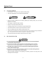
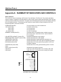
Price $50.00
User's Manual
1600 Watts, PBC-II
Power Backup Cabinet
Doc #. 6002-1210
Revision A
Installation and
Operating Documentation
OnLine Power
SAFETY
Safety precautions are important when operating or servicing electrical equipment. The following symbols
are used extensively throughout this manual. Always read these precautions since they are essential to
the safe operation and servicing of this product.
WARNING!
DANGER!!
RED LABEL
THIS WARNING SYMBOL IDENTIFIES A CONDITION OR ACTION WHICH
WILL RESULT IN SEVERE INJURY OR DEATH TO AN INDIVIDUAL OR
SEVERE DAMAGE TO EQUIPMENT OR OTHER PROPERTY.
YELLOW
LABEL
CAUTION
This Caution symbol identifies a condition or action which may result in minor injury to an
individual or minor damage to the equipment or other property.
a
OnLine Power
IMPORTANT SAFETY INSTRUCTIONS
SAVE THESE INSTRUCTIONS
This manual contains important instructions for the UPS that should be
followed during the installation and for maintenance of the UPS, Electronic
Tray, and the Batteries.
IMPORTANT SAFEGUARDS
When using electrical equipment, basic safety precautions
should all always be followed including the following:
READ AND FOLLOW ALL SAFETY INSTRUCTIONS.
1. DO NOT MOUNT NEAR GAS OR ELECTRIC HEATERS.
2. EQUIPMENT SHOULD BE MOUNTED IN A LOCATION WHERE IT WILL
NOT READILY BE SUBJECT TO TAMPERING BY UNAUTHORIZED
PERSONAL.
3. EQUIPMENT SHOULD BE KEPT UNDER LOCK AND KEY.
4. ONLY QUALIFIED ELECTRICAL PERSONAL SHOULD BE PERMITTED
TO MAINTAIN OR SERVICE EQUIPMENT.
5. ONLY ACCESSORIES OR EQUIPMENT RECOMMEND BY
MANUFACTURER SHALL BE USED WITH THIS EQUIPMENT, CONTACT
FACTORY FOR APPROVAL.
6. CHECK BY INSPECTION THAT ALL ELECTRICAL CONNECTIONS ARE
CLEAN AND TIGHT.
b
OnLine Power
BATTERY SERVICING
1. Servicing of batteries should be performed or supervised by personnel
knowledgeable of batteries and the required precautions. Keep
unauthorized personnel away from batteries.
2. When replacing batteries, replace with the same number of the universal
battery. (See Warning Label on the door of the unit)
WARNING!
•
DO NOT MIX BATTERIES OF DIFFERENT MANUFACTURERS WITHIN THE
SAME CABINET.
•
AT INITIAL INSTALLATION: ANY FAILED BATTERY(S) SHALL BE
REPLACED WITH THE SAME BRAND AND TYPE.
•
AFTER UNIT IS PLACED IN SERVICE: ANY BATTERY(S) FAILURES SHALL
REQUIRE THE REPLACEMENT OF ALL EIGHT (8) BATTERY(S).
Manufacturer
POWER BATTERY CO, BATTERIES ORDERABLE ITEM #300 317 948
C&D TECHNOLOGIES, BATTERIES ORDERABLE ITEM #300 327-764
CAUTION
Do not dispose of battery or batteries in a fire. The battery may
explode.
CAUTION
Do not open or mutilate the battery or batteries. Released
electrolyte is harmful to the skin and eyes. It may be toxic.
c
OnLine Power
CAUTION
A battery can present a risk of electrical shock and high short
circuit current. The following precautions should be observed
when working on batteries:
1) Remove watches, rings, or other metal objects.
2) Use tools with insulated handles.
3) Wear rubber gloves and boots.
4) Do not lay tools or metal parts on top of batteries.
5) Disconnect charging source prior to connecting or disconnecting battery terminals.
6) Determine if the battery is inadvertently grounded. If inadvertently grounded, remove source of
ground. Contact with any part of a grounded battery can result in electrical shock. The likelihood
of such shock will be reduced if such grounds are removed during installation and maintenance
(applicable to a UPS and a remote battery supply not having a grounded supply circuit).
DANGER!!
“HIGH VOLTAGE 96 VDC” LABEL LOCATED NEAR BATTERY JACK ON
FRONT PANEL OF ELECTRONIC TRAY.
WARNING!
ENSURE CONNECTOR P3 / J3 ARE ALWAYS CONNECTED.
FAILURE TO COMPLY WILL OVERCHARGE AND DAMAGE BATTERIES.
WARNING!
LABEL NEAR BATTERY AND ON DOOR INDICATES, “BATTERY IS
HEAVY”. EACH BATTERY WEIGHTS 82 LBS. TWO PERSONS AND
CAUTION ARE REQUIRED WHEN REMOVING BATTERY FROM CABINET.
d
OnLine Power
CAUTION
The Battery Voltage can cause the unit to operate with AC line power “OFF”. Care should
be used at all times.
CAUTION
A Battery can present a risk of electrical shock and have a very high short circuit current.
WARNING!
•
BATTERY SHELF LIFE, WHEN STORED UNDER TEMPERATURE CONDITIONS OF 660F 900F, IS FIVE (5) MONTHS MAXIMUM AFTER THE SHIP DATE.
•
BATTERY MUST BE RECHARGED AFTER THIS DATE OTHERWISE THEY WILL BE
DAMAGED.
•
DTHE SHIP DATE IS PART OF THE SERIAL NUMBER.
Example S/N 00 L7 02
Year
Month
00####
unit I.D. Number
CAUTION
Located near battery location. Battery terminals are coated with PRO-OX to seal and protect. PRO-OX
contains petroleum distillates. WASH HANDS THOROUGHLY AFTER USE WITH SOAP & WATER. If
ingested induce vomiting.
DANGER!!
RISK OF ELECTRIC SHOCK
LOCATED NEAR THE BATTERY LOCATION AND ON DOOR, “DO NOT TOUCH
UNINSULATED BATTERY TERMINAL”.
e
OnLine Power
DANGER!!
LIFTING - LOCATION FOR TWO EYE BOLTS ARE PROVIDED AT TOP.
TWO EYEBOLTS WITH RUBBER WASHERS ARE PROVIDED IN A BAG
INSIDE THE DOOR. DO NOT LIFT CABINET FROM TOP COVER. SEE THE
PRE-INSTALLATION SECTION TO LIFT THE CABINET FROM PALLET
USING FORK LIFT OR USING TWO EYE BOLTS AT TOP.
CAUTION
WEIGHT OF COMPONENTS
. The cabinet weight is approximately 899 lbs with electronic tray.
. The Electronic Tray weight is approximately 55 lbs.
. Each of the eight (8) Batteries weighs 82 lbs.
CAUTION
DOOR STOP - Use Door Stop provided at the bottom lip of the door for human protection
from wind etc..
CAUTION
All power to the unit shall be locked and tagged “OFF” before any servicing or other work
on the unit.
CAUTION
The Battery/UPS door to the unit shall be locked and tagged “OFF” before any servicing or
other work on the unit.
CAUTION
Provide about 6 feet of service loop for power cables, from stub out on a concrete slab or
conduit for roof top application. This will facilitate wire routing in the unit.
f
OnLine Power
CAUTION
GROUNDING - SEE GROUNDING SECTION. CABINET MUST BE GROUNDED USING #2
AWG SOLID TINNED WIRE FROM GROUND ELECTRODE, CRIMPED AT GROUND PADS
USING CABLE LUG AND HARDWARE SUPPLIED AND INSTALLED ON THE GROUND
PADS.
WARNING!
RISK OR ELECTRIC SHOCK HAZARD LIVE PARTS INSIDE THE UPS .
WHEN THE AC INPUT POWER IS DISCONNECTED, THE ENERGY IS
SUPPLIED FROM THE BATTERIES.
WARNING!
THE OVERCURRENT PROTECTION FOR THE OUTPUT AC CIRCUIT IS TO
BE PROVIDED BY OTHERS.
CAUTION
To disconnect all power in the PBC-II cabinet, turn-off Main Input Circuit Breaker CB1, Main
Output Circuit Breaker CB2, Battery Breaker CB9 in the UPS cabinet and Battery Breaker,
CB1 in the adjunct Battery cabinet. All the Breakers in the UPS and battery cabinet should
be turned OFF by pushing handle downward.
CAUTION
Use either No 10 AWG, 60o or 75oC copper wire, or No 12 AWG, 60o or 75oC copper wire
minimum to connect input and output AC power to the unit at terminal blocks. Local Code
must be followed for sizing the wiring to the unit.
g
OnLine Power
WARNING!
RISK OF ELECTRIC SHOCK AND FIRE
USE THE SAME TYPE AND RATING OF FUSE INDICATED TO REDUCE THE
RISK OF FIRE.
WARNING!
HIGH LEAKAGE CURRENT
EARTH CONNECTION ESSENTIAL BEFORE CONNECTING SUPPLY.
CAUTION
Located on the dead front of the Electronic Tray “ELECTRIC SHOCK HAZARD” Do not remove panel. Refer servicing to qualified service personnel.
CAUTION
Located on the dead front of the Electronic Tray, “Risk of electric shock hazard”. Live
parts inside the UPS are energized from the battery supply even when the A.C. Input Power
is disconnected.
h
OnLine Power
TORQUE VALUE
TERMINAL or BOLT
TORQUE
IN/LBS.
N-METER
DEAD FRONT PANEL
49.60
5.61
TB1
18.0
2.03
TB2
18.0
2.03
ELECTRONIC TRAY GROUND
14.16
1.6
TRAY TO CABINET SCREW
49.6
5.61
CIRCUIT BREAKER, TERMINALS
27.0
3.0
SURGE PROTECTOR
25.48
2.88
CONDUIT INLET COVER PLATE
OVER TORQUE WILL DAMAGE THE GASKET
18.24
2.08
BATTERY CONNECTIONS
68.17
7.7
DOOR GND
49.60
5.61
GROUND LUGS, ON OUTSIDE
49.60
5.61
PAD MOUNTING BRACKET
84.96
9.6
This unit was designed for specific applications. It should not be modified and/or used for any application
other than for that which it was designed. Optional equipment not described in the sales literature or this
manual should not be installed without first checking with the Service department. If you have any
questions about this unit’s application call the Service department at the number shown on the page f.
i
OnLine Power
Congratulations on selecting one of the fine products from OnLine Power, the Leader in Power Protection
Technology. Our wide product offering includes Uninterruptible Power Systems (UPS), Power
Conditioners, Automatic Voltage Regulators and Specialty Transformers (e.g. computer-grade,
medical-grade). Since our beginnings in 1975, OnLine Power has shipped thousands of these fine
products around the world, to discerning customers, for use on sensitive equipment and critical
applications. Our customers, both new and long-time, continue to enjoy security and peace of mind as
they realize what it means to ”Stay OnLine with On-Line Power”.
One of our goals is to make these manuals both comprehensive and easy to use. This new-format
Technical Manual is the result of ideas and inputs from customers who have taken an active interest in our
continued success. We invite constructive feedback on our products and documentation via fax, mail or
telephone.
HEADQUARTERS
On-Line Power, Inc.
5701 Smithway Street
Commerce, CA 90040
SALES
Phone
(800) 227-8899
Inside CA (323) 721-5017
FAX No.
(323) 721-3929
http://www.onlinepower.com
email: [email protected]
SERVICE
Phone
FAX No.
(800) 797-7782
(PWR-SRVC)
(323) 721-3929
j
OnLine Power
OnLine Power, Inc.
Proprietary Reproduction or Distribution forbidden
NOTICE: THIS DOCUMENT CONTAINS PROPRIETARY INFORMATION
This document contains proprietary and confidential information of OnLine Power, Inc. (”OnLine Power”).
In consideration of the receipt of this document, the recipient agrees not to copy any of its contents, nor
disclose them to or allow them to be used by any person not currently a OnLine Power employee or an
employee of the recipient having a need to know, without the express written consent of OnLine Power,
and further agrees to surrender this document to OnLine Power when the reason for its receipt has
terminated.
k
OnLine Power
REV A
REVISION HISTORY
REV
A
DATE
PRIMARY REASON FOR CHANGE
April 20, 2008
Release for Production
LIST OF EFFECTIVE PAGES
PAGE
Title Page
A
a to j
i to ii
1-1 to 1-20
2-1 to 2-1
3-1 to 3-6
4-1 to 4-3
A-1 to A-2
B-1
C-1 to C-2
D-1 to D-2
E-1 to E-2
REV
PAGE
REV
PAGE
REV
A
A
A
A
A
A
A
A
A
A
A
A
A
A
PAGE
REV
PAGE
REV
OnLine Power
REV A
TABLE OF CONTENTS
SECTION
PAGE
SECTION 1 - OPERATION
1-1
1-2
1-3
1-4
1-5
1-6
1-7
1-8
1-9
1-1
OVERVIEW
FEATURE
1-2-1
Alarm Signals
1-2-2
Alarm Cables
1-2-3
Intrusion Switch
1-2-4
ESD Receptacle and Wrist Strap
RUGGEDIZATION FEATURE
1-3-1
Wide Temperature Range
1-3-2
Shock and Vibration
1-3-3
High Input Voltage Surge Withstand Capability
1-3-4
Corrosion Resistant Cabinet
1-3-5
Rain-Proofed Cabinet
1-3-6
Easy Front Door Access
MOUNTING FEATURE
SAFETY AND EMI REGULATORY ASPECTS
OTHER IMPORTANT DESIGN FEATURES
1-6-1
Modularity of Internal Components
1-6-2
Electronic Tray
1-6-3
Battery
1-6-4
Temperature Compensated Fast Battery Charger (A7 PCBA)
1-6-5
External Padlock
1-6-6
Over Temperature Shutdown
1-6-7
Over Current Protection
1-6-8
Auto Bypass Feature
1-6-9
System Operation
ELECTRICAL - INPUT/OUTPUTS
MECHANICAL OVERALL OUTLINE
THEORY OF OPERATION
SECTION 2 - PREINSTALLATION
2-1
2-2
2-3
2-4
2-1
SITE PLANNING AND PREPARATION
POSITIONING
SITE PLANNING SPECIFICATIONS
SITE DETAIL ELECTRICAL SPECIFICATIONS
SECTION 3 - INSTALLATION AND OPERATION
3-1
3-2
3-3
3-4
3-5
3-6
3-7
3-8
3-9
3-10
1-1
1-1
1-2
1-3
1-3
1-4
1-4
1-4
1-4
1-4
1-4
1-4
1-4
1-5
1-5
1-5
1-5
1-5
1-6
1-6
1-6
1-7
1-7
1-7
1-7
1-8
1-8
1-9
PBC-II UNPACKING
INSPECTION
PBC-II STORAGE
PBC-II INSTALLATION
LIFTING REQUIREMENTS
PBC-II POLE INSTALLATION
POWER BACKUP CABINET TO POLE GROUNDING
POWER BACKUP CABINET GROUNDING TEST
PBC-II CONDUIT INSTALLATION
ELECTRONIC TRAY WIRING
i
2-1
2-1
2-1
2-2
3-1
3-1
3-1
3-2
3-2
3-3
3-3
3-5
3-5
3-6
3-6
OnLine Power
REV A
PAGE
SECTION
SECTION 3 - INSTALLATION AND OPERATION (Continued)
3-11
3-12
3-13
3-14
3-15
3-16
3-17
INPUT AND OUTPUT WIRING (TB1)
WIRING FOR OPTIONAL BATTERY HEATERS
ELECTRONIC TRAY, WIRING CHECK OUT
PBC-II BATTERY CONNECTION
PBC-II POWER UP PROCEDURE
PBC-II BATTERY BACK-UP OPERATION TEST
PBC-II PAD LAYOUT
SECTION 4 - SERVICING THE PBC-II
4-1
4-2
4-3
4-4
4-5
4-6
3-6
3-8
3-9
3-9
3-9
3-9
3-10
4-1
THE MODULARITY OF INTERNAL COMPONENTS.
SERVICING (STARTS WITH SAFETY)
REMOVAL OF ELECTRONIC TRAY FOR SERVICING
REPLACING OF ELECTRONIC TRAY
BATTERY REMOVAL AND SERVICING
REPLACING BATTERY
4-1
4-1
4-2
4-2
4-2
4-3
APPENDIX
Appendix A.
Appendix B.
Appendix C.
Appendix D.
Appendix E.
SUMMARY OF INDICATORS AND CONTROLS .
INSTALLATION ACCESSORY KITS .
BATTERY MAINTENANCE TESTING AND SPECIFICATIONS .
TROUBLESHOOTING.
SUMMARY OF ALL ALARMS AND FUNCTIONS .
A-1
B-1
C-1
D-1
E-1
LIST OF ILLUSTRATIONS
PAGE
ILLUSTRATION
1-1
1-2
1-3
1-4
1-5
1-6
1-7
1-8
STATUS PANEL
DB9 CONTACTS
BATTERY TRAY
POWER BACKUP CABINET OVERALL DIMENSIONS
PBC-II SYSTEM SCHEMATIC DIAGRAM (120 VOLT UNIT)
PBC-II SYSTEM SCHEMATIC DIAGRAM (230 VOLT UNIT)
BATTERY CABINET SCHEMATIC DIAGRAM (120 VOLT UNIT)
BATTERY CABINET SCHEMATIC DIAGRAM (230 VOLT UNIT)
2-1
PBC-II FRAME FABRICATION DETAIL
3-1
3-2
3-3
3-4
3-5
3-6
PBC-II POLE MOUNTING
CABINET CONDUIT LOCATION
CONNECTIONS AT TB1 OF MAIN UPS CABINET
CONNECTIONS TO ADJUNCT BATTERY CABINET
WIRING FOR OPTIONAL BATTERY HEATERS
PBC-II LAYOUT
4-1
FRONT VIEW
1-2
1-2
1-6
1-8
1-9
1-10
1-11
1-11
2-2
3-4
3-6
3-7
3-8
3-8
3-10
4-1
ii
OnLine Power
REV A
SECTION 1 - INTRODUCTION
1-1
OVERVIEW
Within each Power Backup Cabinet is an Uninterruptible Power Supply (UPS). The purpose of this device is to
provide power to the critical load during brown out, or black out conditions, without disruption of operation of the load
equipment. When the unit operates in the backup mode, the AC power for the load comes from a set of internal
batteries and Inverter. The battery charger keeps the batteries charged and ready to fulfill the unit’s function to
supply reserve power.
Also, PBC-II cabinet provides an additional level of power protection from transients, surges, electrical noise, and
other power disturbances.
What differentiates this PBC-II from, off-the-shelf, UPS equipment is the high level to which these units have
been ”hardened” ( ruggedized ) to ensure continuous operation in very harsh environments, particularly outdoors.
1-2
FEATURES
Status Indicators
The unit has two major components, the Electronic Tray and Battery. The Electronic Tray contains the battery
charger, breakers, receptacles, LED status panel, Inverter circuitry, and the input/output terminals. Each of the two
lower tray holds four batteries on each shelf. The lights on the LED status panel (at the front panel display) indicates
the unit’s operational mode. (See Illustration 1-1 below) These lamps provide a positive visual indication of specific
aspects of the unit’s functional operation. These are as follows:
OVERLOAD (Red LED)
100% (Green LED)
(Green LED)
(Green LED)
25% (Green LED)
SUMMARY ALARM (Red LED)
HIGH BATTERY CAPACITY (Green LED)
MEDIUM BATTERY CAPACITY (Green LED)
LOW BATTERY (Red LED)
ON BATTERY (Green LED)
BYPASS ON (Green LED)
INVERTER ON (Green LED)
mode.
INPUT AC ON (Green LED)
UPS OFF S1
UPS ON S2
The output load is over 100% of rated load.
Full load of 100% rating.
75% of rated load.
50% of rated load.
0 to 25% of rated load.
Illuminates when unit shutdown alarm condition is present
such as over temp., output short circuit, output overload, &
DC overvoltage
Indicates the batteries are fully charged
Indicates the batteries are half charged
Indicates the battery is approaching low shutdown level.
Indicates the battery is ON, and output is supplied from battery.
Indicates the unit is running with AC input power in OFF Line,
AC Mode, in Bypass.
Indicates the unit is running with the battery power in Inverter
Indicates the input power is present.
Used only to shut-off UPS when unit is running in DC mode.
Used only to turn on UPS when unit is running in DC mode.
1-1
OnLine Power
REV A
OVER LOAD
100%
LOAD IN
PERCENTAGE
OF RATED AMPS
25%
SUMMARY ALARM
HIGH BATTERY CAPACITY
MEDIUM BATTERY CAPACITY
LOW BATTERY
GREEN
ON BATTERY
RED
BYPASS ON
SWITCH
INVERTER ON
INPUT AC ON
UPS OFF S1
UPS ON S2
ELECTRONIC TRAY - STATUS PANEL
ILLUSTRATION 1-1
In the normal running condition, “Input AC ON” (Green LED) and “Bypass ON” (Green LED) is lit ON indicating that
input AC power is available and unit is running in AC mode (Off-Line), in Bypass mode. When input power is lost or
disappears, “Input AC ON” green LED shuts OFF, “Bypass ON” green LED shuts OFF. “ON Battery” and “Inverter
ON” green LEDs lit ON indicating that output power is supplied from battery & inverter (unit is running on battery and
inverter).
1-2-1 Alarm Signals
Also providing information on the unit’s status/particular aspects to the outside world by way of electrical signals is a
DB-9 connector. This DB-9 connector is located on the front console of the Electronic Tray. This interface provides
a set of open and closed contacts, which relate the status of PBC-II to the outside world. An interface DB-9
connector and cable permit the unit to bring out following signals with their normal state (open or closed). The
contacts (Normally Open or Normally Closed) is shown when unit is running in normal condition (i.e. with input
power present and everything normal within limit).
ON Battery
(Normally Open)
Summary Alarm
(Normally Open)
5
4
9
Input AC ON
(Normally Open)
3
8
2
7
1
6
Door Switch
(Normally Open)
Low Battery
(Normally Open)
UPS ON (Normally Close)
DB9 CONTACTS
ILLUSTRATION 1-2
1-2
NOTE: Relays are dry contacts
rated 2 AMPS @ 250 VAC
OnLine Power
REV A
•
DB9 Pin
Numbers
UPS Power-Off,
all CB’s open
condition
Normal Operating
Condition (Input
AC On, UPS On)
Failure/Alarm Condition
Alarm Description
3 to 5
OPEN
OPEN
CLOSE, Latched (for short
circuit and overload)
Summary Alarm
7 to 5
OPEN
OPEN
CLOSE
Low Battery
2 to 5
OPEN
OPEN
CLOSE (UPS battery on)
On Battery
8 to 5
OPEN
CLOSE
OPEN (UPS OFF)
UPS On (”bypass on” or
“inverter on”)
9 to 5
CLOSE
OPEN
CLOSE (input power-off)
Input AC ON
1 to 6
OPEN for door
close
OPEN
CLOSE (door open)
Intrusion Door Switch
For the detailed pin out for the DB-9 connector see Illustration 1-2 and table below.
1-2-2 Alarm Cables
The PBC-II units come with an Alarm Cable, 20 feet long, which connects to the “DB-9 jack” at the electronic tray,
below TB1, so the signals are available for external monitoring/status reporting equipment. The wiring of the cable
matches the pin out detail as shown in Illustration 1-2 for the DB-9 jack.
DB9 Pin Out
Wire Color
Function
Contact Position
with Power OFF
1
Black of Black / Blue
Door Switch, Intrusion Alarm
Normally Open
2
Black of Black / Red
ON BATTERY(*)
Normally Open
3
Black of Black / White
Summary Alarm Warning
Normally Open
Open no wire
N/A
4
5
Black of Black / Green
Return Common
Ground
6
Blue of Black / Blue
Door Switch, Intrusion Switch
Normally Open
7
Red of Black / Red
Low Battery
Normally Open
8
White of Black / White
UPS “ON” / Inverter “ON”
Normally Open
9
Green of Black / Green
Input Failed
Normally Closed
(*) NOTE: Disregard the “FLASH” label attached to the wire connected at DB9 pin #2, in the unit.
1-2-3 Intrusion Switch
An intrusion alarm switch resides within the cabinet to relay that the unwanted entrance into the cabinet has been
made. The plunger of the switch is in by the door when it’s closed. In this condition, the switch presents an open
circuit and the alarm is in the ”off” state. When the door is open, the switch presents a closed circuit with a pulled out
plunger and the alarm is in the ”on” state. One additional state is available on the switch. A technician working on the
unit can pull the plunger completely out to a ”neutral” position. The switch will be in the open state ( ”off” ) and thus
no alarm condition by-passed while he or she is working on the unit. See Illustration 1-3 for its location.
1-3
OnLine Power
REV A
1-2-4 ESD Receptacle and Wrist Strap
The ESD wrist strap plugs into the red connector receptacle on the front panel of the Electronic Tray. An ESD wrist
strap is in the bottom of the cabinet. Any personnel working on the unit should be wearing the strap. The strap plugs
into the RED banana plug receptacle to minimize the risk of damage to the ESD sensitive circuitry that of the
electronics assembly.
1-3
RUGGEDIZATION FEATURES
All PBC-II are designed to operate in most outdoors harsh environments. The unit has been subjected to outside
independent labs to demonstrate that they are capable of withstanding severe outdoors operating conditions.
Below is a listing of many of those conditions:
1-3-1 Wide Temperature Range
The PBC-II designed and tested to operate in the outdoors over a wide range of temperatures, from -400C to +460C
plus a solar load of 70 watts/sq.ft. The PBC-II unit has option of having internal heaters for the batteries to allow it to
operate over a range of -400C to +460C.
1-3-2 Shock and Vibration
These devices are designed and tested to meet Bellcore specs for shock and vibration namely GR-63-Core Issue 1
section 4.3 and GR-63-Core issue 1 section 4.4 and earthquake zone 4.
1-3-3 High Input Voltage Surge Withstand Capability
The unit internally has AC Surge protector (ACT’s TVSS) to ensure that lightning or other types of high voltage
surges do not damage them. They meet IEEE 62.41 1991 (UL1449) level C3 input voltage surge, of 20,000 Volts @
10,000 Amps.
1-3-4 Corrosion Resistant Cabinet
The cabinet is aluminum - anodized and painted on the exterior. It is a sealed cabinet having drain holes at the
bottom and vents for hydrogen gas at top.
1-3-5 Rain-Proofed Cabinet
The cabinets designed and tested to meet UL50 (Type 3R) and IEC60529 (IP34) requirements and thereby to
ensure that rain will not reach the critical electronics.
1-3-6 Easy Front Door Access
This makes for effective field service access.
1-4
OnLine Power
REV A
1-4
MOUNTING FEATURES
Pad or Floor Mounting
PBC-II shall mount on a concrete pad, outdoor/indoor. The pad rail mounting comes with the hardware required.
The rails can be in-line with door or crossways to door.
Pole or Wall Mounting
PBC-II can be Pole or Wall mounted. The mounting brackets are optional and need to be ordered. Select options at
the time of purchase of individual units. The part numbers for these options are part of Appendix B of this manual.
1-5
SAFETY COMPLIANCES
The PBC-II units are UL listed and evaluated for compliance to standards for UL 1778 and cUL listed and evaluated
fro compliance to standards for CAN/CSA - C22.2-107.1.
The unit is evaluated by UL for outdoor use to be type 3R (for North American) and IP34 (for International)
The PBC-II units are tested and evaluated to be in compliance by ITS for followings
1-6
•
IEC 60950
•
IEC 600529 (IP34)
•
EN 55022 (CISPR)
•
GR-1089-CORE: 1997 (Section 3, Rediated immunity and conduited immunity)
•
IEC 61000-4-2: 1999
•
IEC 61000-4-3: 1998
•
IEC 61000-4-5: 1995
•
IEC 61000-4-6: 1996
•
CFR NO. 47 Telecommunication: Oct 1, 1999 FCC Part 15, Subpart B, Class B
OTHER IMPORTANT DESIGN FEATURES
1-6-1 Modularity of Internal Components
The cabinet contains two physical assemblies; The Electronic Tray and Individual Batteries.
The Electronic Tray contains the UPS System.
1-6-2 Electronic Tray
The electronic tray can be accessed after removal of front panel, held by 4 captive screws in four corners. The
electronic tray consist of two levels and a front section. The front section contains breakers, receptacles, display
lights etc... The two levels inside contains UPS and electronics. Details of the connectors are shown in Section 3
for electrical wiring of unit.
1-5
OnLine Power
REV A
1-6-3 Battery
The batteries are on two level compartments and supplying 96 VDC to UPS. There is an optional Adjunct Battery
Cabinet with 8 batteries that are mounted in two trays, supplying 96 VDC nominal to UPS.
The batteries are mounted on the two level compartments and supplying 96VDC to UPS. Use quantity of 8x120A/H
or 8x100AH batteries. There is a heater option to ensure operation down to -40 degree C. temperature. The total
number of heater pad assembly is 4.
The simplified construction into two major components makes for fast and easy repair of the unit in the field where
the batteries, and Electronics Tray composes the only FRU items within the unit.
Thermoprobe
location on the
bottom battery tray
Battery
Heater (Optional)
Battery
Heater (Optional)
Connector P3
BATTERY TRAY
ILLUSTRATION 1-3
1-6-4 Temperature Compensated Fast Battery Charger (A6-A PCBA)
The Fast Charger will charge the batteries when discharged, as well as to keep the batteries charged. The
recharging time varies based on the backup time and the critical load supported by the batteries during the input
power outage.
The thermoprobe located on bottom battery tray and as shown above in Illustration 1-3, monitors the battery
temperature and compensate the battery charging voltage out of the battery charger. The connector for the
thermoprobe, J3/P3 must be connected at all times. The batteries will be overcharging if J3/P3 connector is left
open and eventually batteries will be damaged, since this condition is not reported by any alarms. When the
temperature at battery case is very low, as sensed by the thermoprobe, the charger will charge the batteries at
higher voltage. When the battery case temperature is sensed high by thermoprobe, the charger reduces the
charging voltage.
1-6-5 External Padlock
The cabinet possesses an external padlock receptacle to prevent unauthorized personnel from gaining access to
the interior of the cabinet via the front door when used in conjunction with a customer supplied padlock.
1-6
OnLine Power
REV A
1-6-6 Over Temperature Shutdown
While the PBC-II has several internal fans operating when the PBC-II & UPS Is ” ON ” to prevent an overheating
condition, further protection has been built into the UPS to ensure against circuit failure due to internal overheating.
If there is an Over Temperature condition, the UPS shall shut down. It has an auto-recovery feature, so that when
the temperature reaches a safe level, the UPS will come back on. There is a built-in hysteresis feature to prevent
any oscillatory condition of the UPS turning ” ON ” and ”OFF” at the Over Temperature trip point from taking place.
For overtemperature alarm condition and description, see Appendix A and E at the end.
1-6-7 Over Current Protection
If there is an overload or loads draw excessive output current from the PBC-II. The sensing circuit in the Inverter will
provide feedback to cause the Inverter to limit the current and thereby prevent the unit from being damaged due to
such a condition. For overload of over 160% of rated capacity, unit will shut down and/or trip breakers, same as in
output short circuit condition. For overload of 120% to 160% of rated capacity, “Summary Alarm” comes ON and the
unit may support the output load via automatic bypass circuit. See Appendix E at the end for details.
1-6-8 Auto Bypass Feature
This feature allows input power to bypass the electronics and UPS automatically. It detects the low or no output
voltage of the UPS and energizes the autobypass relay, whose contacts provides output power (from input or
battery, i.e. in AC or DC mode) to the main output breaker. The relay deenergizes or opens when output power falls
below the limit or disappears for any of the reason (such as overtemperature or any failure), thereby disconnecting
the UPS from output circuits. The normally close contacts of this relay provides input power to the output circuit with
this feature. As long as input power is available, it is provided to output circuits for continuous operation of
microcells, even though UPS may have been shut-off indicating “Summary Alarm” in the unit as well as in central
station via DB9 cable. See Appendix A and E for “Customer Action” under “Summary Alarm Conditions”.
1-6-9 System Operation
This PBC-II is supplying the power to critical load through bypass circuit directly by the input power source as long
as the input voltage range is within the voltage specification such as 85 V - 130 V for 120 Volt unit, 180 V - 264 V for
230 Volt unit. When the input voltages are out of the above specifications or fails, the unit will automatically transfer
to the battery and inverter to supply the critical load. When the input comes back to normal, then unit will supply
critical load automatically from the input source.
The transferring time from input power to battery or battery to input power is within 4.2 - 10 milliseconds at 100%
load condition.
1-7
OnLine Power
REV A
1-7
ELECTRICAL - INPUT/OUTPUTS
All models are single phase input and outputs.
AC Mode (Normal Off-line Operation)
Model
120 V, 50/60 Hz
230 V, 50/60 Hz
Rating
1600 W
1600 W
Input Voltage
120 VAC
208 - 240 VAC
Input/Output Frequency
47-53 / 57-63 Hz
47-53 / 57-63 Hz
Input Breaker (CB1)
32 Amps
16 Amps
Output Voltage
120 VAC
208 - 240 VAC*
Main Output Breaker (CB2)
20 Amps
10 Amps
RCD/GFCI Breaker (CB3)
16 Amps
16 Amps
Secondary Output Breakers
(CB4-CB7)
20 Amps
10 Amps
*The output voltage in DC mode (Battery Back-up Operation), will be 230 VAC.
1-8
MECHANICAL OVERALL OUTLINE
POWER BACKUP CABINET OVERALL DIMENSIONS
ILLUSTRATION 1-4
1-8
OnLine Power
REV A
1-9
THEORY OF OPERATION
• System schematic diagram shows the power path through PBC-II. See Illustration 1-5 for 120 Volt
unit, Illustration 1-6 for 230V unit, Illustration 1-7 for optional 120V Adjunct Battery Cabinet, and
Illustration 1-8 for optional 230V Adjunct Battery Cabinet. There is an option for extra 4 hours
battery run time. The optional Adjunct Battery Cabinet provides an additional 4 hours of battery
backup time. The main cabinet provides 4 hours of battery backup time, as a standard feature.
•
Input Stage
Utility power enters the system through input circuit breaker from terminal block TB1-1, 1-2, and 1-3.
The capacitors C2, C3, and C4 and EMI filter (A3) are for EMC requirements of FCC, 47CFR, Part
15, Subpart B.
Surge suppressor after the CB1 protect the unit for impulse class “B” requirement.
•
Power Conditions Stage.
The input power is applied to the power PCBD assy through CN3L and CN3N and also is applied to
the Battery charger PCBD (A6-A). The power PCBD assy (A1-A) with control PCBD assy (A1-B)
monitors the input voltage at all the time for the input voltage range specifications such as 85 Volt 130 Volt for 120 Volt unit and 180 V - 264 V for 230 Volt unit.
When the input voltage is within the range specification, the input power will support the critical load.
The output voltage to the critical load will be same as the input voltage and will vary according to the
input voltage variation. It is called “off-line technology” U.P.S.
When the input voltage range is out of the range specification, then microprocessor controlled logic
(A1-B) initiates the immediate transferring to the battery and the inverter will support the critical load
now from battery power without any output power interruption. The transfer time is within 4.3
milliseconds - 10 milliseconds with 100% load condition. If the load is less than 100% load, the
transfer time is less. When any alarms such as overtemperature or overcurrent, over voltage or
under voltage occur while the inverter supplies the power to critical load from the battery, the
inverter will shut-off and try to by-pass to the input power source. (See Appendix E at the end.)
1-9
OnLine Power
REV A
PBC-II SYSTEM SCHEMATIC DIAGRAM (120 VOLT UNIT)
ILLUSTRATION 1-5
1-10
OnLine Power
REV A
PBC-II SYSTEM SCHEMATIC DIAGRAM (230 VOLT UNIT)
ILLUSTRATION 1-6
1-11
OnLine Power
REV A
OPTIONAL ADJUNCT BATTERY CABINET SCHEMATIC DIAGRAM (120 VOLT UNIT)
ILLUSTRATION 1-7
1-12
OnLine Power
REV A
OPTIONAL ADJUNCT BATTERY CABINET SCHEMATIC DIAGRAM (230 VOLT UNIT)
ILLUSTRATION 1-8
1-13
OnLine Power
REV A
SECTION 2 - PREINSTALLATION
2-1
2-2
SITE PLANNING AND PREPARATION
• Provide an operating environment that meets the following conditions:
•
Ambient Temperature is 00C to 40 O0C ( 320F to 104 O0F )
•
Relative Humidity is 10 to 95 % Non-Condensing.
Positioning
• Door shall have full 110 degrees open clearance, and have 5 feet clearance in front for bucket or
platform.
DANGER!!
CAUTION
•
Inspection Safety Zone of Tray is 6 inches. Pass that point, the tray needs support, due to weight.
•
The Electronic Tray weight is approximately 55 lbs.
•
Each of the eight Battery weight is 82 lbs (for a total of 656 lbs. for 8 batteries).
•
The PBC-II weight is approximately 892 to 899 lbs.
2-3
Site Planning Specifications
DC Mode:
NOMINAL INPUT VOLTAGE
Input Voltage Range
Max. Input Voltage
Input Frequency
Output Frequency
*Output Voltage
208 VAC
180-264
264 VAC
60
60 +/- 0.5%
230V +/-3%
230 VAC
180-264
264 VAC
60
60 +/- 0.5%
230V +/-3%
120 VAC
85-130
130 VAC
60
60 +/- 0.5%
120V +/-3%
220 VAC
180-264
264 VAC
50
50 +/- 0.5%
230V +/-3%
*Output voltage vary and follow the input voltage in normal AC mode operation.
2-1
240 VAC
180-264
264 VAC
60
60 +/- 0.5%
230V +/-3%
OnLine Power
REV A
2-4
Site Detail Electrical Specifications
PBC-II FRAME FABRICATION DETAIL
ILLUSTRATION 2-1
2-2
OnLine Power
REV A
SECTION 3 - INSTALLATION AND OPERATION
3-1
PBC-II UNPACKING
• The unit is delivered on a pallet, secured using metal bands. On removing the PBC-II from the pallet, be
sure to keep the protective wrapping in place. Use the following procedure to unpack the unit.
• Position the pallet away from walls or other obstructions.
• Be sure pallet is sitting level where bands can not hit anything.
WARNING!
CAUTION
Exercise extreme caution as you cut the metal bands. They are under tension and may
cause injury.
• Carefully remove the cardboard cover from unit; avoid puncturing the plastic bubble wrap with any sharp
object that may damage the surface of unit.
• The bubbles wrap covers the PBC-II and should be removed at location when the unit is to be mounted.
• Save the packing material to allow it to be used to keep the unit covered and protected until start- up.
• Place units in location where it’s used, then remove protective plastic film.
• Before final positioning of unit, verify that all cable routing and raceway are in the correct position.
3-2
INSPECTION
• Inspect the PBC-II for obvious damage or safety hazards that may have occurred during shipping or
handling of unit.
•
Inspect all units when received and before use.
•
Inspect four (4) batteries located on each of the bottom and middle shelf to verify for no physical
damages nor any leakage thru battery.
•
Report any damage immediately to the originating factory, or to an authorized representative.
•
Initiate Freight damage claims with the carrier as soon as possible.
•
Compare the contents and model numbers with the packing list to ensure that all of the items were
received.
3-1
OnLine Power
REV A
3-3
PBC-II STORAGE
• The batteries are installed in the PBC-II. For details of battery shelf time read appendix C.
•
Provide a protected environment that meets the environmental limits listed below.
•
Storage and Transport Temperature Range is - 40oC to +60oC
•
Relative humidity: 0 % to 95 % non-condensing (inside cabinet).
WARNING!
BATTERY SHELF LIFE!
WHEN STORED UNDER TEMPERATURE CONDITIONS OF 66 DEGREE F - 90
DEGREE F, IS FIVE (5) MONTHS MAXIMUM AFTER THE SHIP DATE.
•
3-4
For the BATTERY SHELF LIFE DETAILS read Appendix C.
PBC-II INSTALLATION
Installation of PBC-II has the following steps:
•
The unpacking of PBC-II covered in section 3.1 & 3.2.
•
The PBC-II installation and mounting.
•
Connecting of conduit to PBC-II cabinet
•
Connecting DB-9 to control panel.
•
Wiring input power to unit at TB-1.
•
Wiring output power from unit at TB-1.
•
Powering up the PBC-II unit & testing it.
•
Power up the output circuits & check loading.
3-2
OnLine Power
REV A
3-5
LIFTING REQUIREMENTS
• See Illustration 3-1 for location of two eyebolts and lifting details.
•
Use Load - Rated Snaps on end of chain and a Spreader Bar.
WARNING!
CAUTION
3-6
•
Because the PBC-II Cabinets and it’s contents, (batteries) are extremely heavy, the use of Power
Equipment is necessary.
•
Total weight for 1600W PBC Model is 899 lbs.
•
Electronic Tray weight is approximately 55 lbs.
•
The Battery weight, with a set of 8 batteries, is approximately 656 lbs.
•
Power Backup Cabinet enclosure weight is approximately is 203 lbs.
•
Pole mount adapter plates with hardware is approximately 10 lbs.
•
Verify that the two eyebolts are secured and screwed at the top of the cabinet by turning it clockwise till
tight. Two eyebolts with rubber washers are supplied in a bag inside the cabinet.
•
Unit may be lifted using two eyebolts, located at the top roof of cabinet.
PBC-II POLE INSTALLATION
CAUTION
a) A service disconnect switch having overcurrent protection is to be connected between
the UPS and the utility transformer.
b) A bucket truck and other suitable equipment, including climbing spikes and safety
harness are to be used during installation or servicing of the UPS on the utility pole.
c) The utility power conductors are to be connected to this UPS through an appropriate
service entrance weather head.
d) Permission to mount the UPS on the utility pole shall be in accordance with agreements
between the cable company and the utility company.
•
With the successful completion of the unpacking of the PBC-II, proceed to next step, which is the
mounting of the unit to the pole.
3-3
OnLine Power
REV A
•
Ensure that all of the appropriate hardware is available for the mounting (See Appendix B for list of
components supplied with the Accessory Kit and ensure that Pole Mounting Brackets and hardware are
available.
•
See illustration 3-1, which shows the unit installed with pole mount fiixture. See Table 3.1 for the part
numbers of the required parts.
•
For the mounting of the weldment on the pole, see Illustration 3-1 for assembly details.
•
Check to see the center to center spacing of the weldments is correct, and the bolt hole alignment
matches.
•
Using the lifting eyes on the top of the unit, rig the unit for lifting with the PBC-II in balance and level from
side to side is correct.
•
Install the bottom bolts first and tighten. Leave the bolt a little loose to permit some play.
•
Install the top bolts and tighten, leave the bolt a little loose to permit some play.
PBC-II POLE MOUNTING
ILLUSTRATION 3-1
Note: For pole mounting details, see Lucent Installation Manual.
3-4
OnLine Power
REV A
3-7
POWER BACKUP CABINET TO POLE GROUNDING
• Install the ground jumper and ground cables at external ground pad as shown in Illustration 3-2 and
Table 3-1 Ground Kit.
TABLE 3-1
Part of List 35 or 36 (see Appendix B)
POLE MOUNTING CABINET GROUND KIT
ITEM
3-8
DESCRIPTION
QTY
OLP P/N
1
Compression Connector, 6 AWG, 2 Hole Lug
2
1200-182
2
M6 x 16 mm, Screw, Hex Head, S.S.
4
1800-300
3
M6, Washer, Split, S.S.
4
1825-085
4
M6, Washer, Flat, S.S.
4
1825-084
5
6 AWG, Wire Stranding, Green, Grounding by 26 inches
2
4000-090
6
2 AWG, Wire Strand, Green, Grounding Bus, reference only Contractor
Supplied
x
Contractor
Supplied
7
C-Tap, 12-1/0 AWG Burndy
2
1200-171
•
Inspect the ground jumper and ground cable connections for good crimp.
•
Inspect the ground connection in both rear corners of the cabinet to the lower left, rear corner of the
door at the hinge side.
•
Inspect the M 6 hex head screws for torque of 7.7 ( N 2 m ) compression lugs on lower rear
corners.
•
Tighten all bolts to a torque of 7.7 ( N 2 m ). Apply one drop of Torque-Seal to each bolt.
POWER BACKUP CABINET GROUNDING TEST
•
Grounding Test requires a Digital Multimeter similar to a Fluke model 87 True rms. MULTIMETER,
•
With a MULTI-METER check the resistance between the ground pole cable to the grounding of the
cabinet door, the reading shall be less than 0.01 ohms.
•
With a MULTI-METER check the resistance between the ground pole cable to the TB1-3, the
reading shall be less than 0.01 ohms.
CAUTION
Make sure ALL POWER to PBC-II is Tagged Out & LOCK “OFF” Before working on the
Power Backup Cabinet Electrical System.
3-5
OnLine Power
REV A
3/4" or 1" Conduit
Knock out holes
(typ. 6)
Rear Hatch-Plate
1/2" Conduit Knock
out holes (typ. 2)
Side Hatch-Plate
CONDUIT LANDING HATCH-PLATE
NOTE: The cabinet comes with
One pre-punched knockout hatch-plate installed
and One blank hatch-plate installed
CABINET CONDUIT LOCATION
ILLUSTRATION 3-2
3-9
PBC-II CONDUIT INSTALLATION
See Lucent Technical Installation Manual for details
3-10
ELECTRONIC TRAY WIRING
See Lucent Technical Installation Manual for details
3-11
INPUT & OUTPUT WIRING (TB1)
•
Connect three (3) input power wires (No 12AWG or higher) at TB1-1, 2, and 3.
•
Connect outputs #1 through #4 at TB1-4 through TB1-15 (as required)
•
Connect TB1-16 through TB1-23 and Connector J13 to the optional Adjunct Battery Cabinet using
supplied interconnect kit as follows. Connector J13 and wiring at TB1-16 through TB1-23 is not
used, when the optional Adjunct Battery Cabinet is not used.
3-6
OnLine Power
REV A
DOOR
SWITCH
G
(-)
(+)
23
22
21
20
19
OUTPUT POWER
INPUT
HEATER
VOLTAGE
CB7
CB6
CB5
INPUT
POWER
CB4
G
N
L
G
N
L
G
N
L
G
N
L
G
N
L
G
N
L
18
17
16
15
14
13
12
11
10
9
8
7
6
5
4
3
2
1
TO ADJUNCT BATTERY CABINET
CONNECTIONS AT TB1 OF MAIN UPS CABINET
ILLUSTRATION 3-3
TB1-1
INPUT VOLTAGE - HOT LINE
TB1-2
INPUT VOLTAGE - NEUTRAL FOR 120V, LOW LINE FOR OTHER VOLTAGES
TB1-3
INPUT GND
TB1-4
OUTPUT #1 - HOT LINE
TB1-5
OUTPUT #1 - NEUTRAL FOR 120V, LOW LINE FOR OTHER VOLTAGES
TB1-6
OUTPUT #1 - GND
TB1-7
OUTPUT #2- HOT LINE
TB1-8
OUTPUT #2 - NEUTRAL FOR 120V, LOW LINE FOR OTHER VOLTAGES
TB1-9
OUTPUT #2 - GND
TB1-10
OUTPUT #3- HOT LINE
TB1-11
OUTPUT #3 - NEUTRAL FOR 120V, LOW LINE FOR OTHER VOLTAGES
TB1-12
OUTPUT #3 - GND
TB1-13
OUTPUT #4- HOT LINE
TB1-14
OUTPUT #4 - NEUTRAL FOR 120V, LOW LINE FOR OTHER VOLTAGES
TB1-15
OUTPUT #4 - GND
TB1-16
HEATER VOLTAGE - HOT LINE FOR OPTIONAL ADJUNCT BATTERY CABINET
TB1-17
HEATER VOLTAGE - NEUTRAL FOR 120V, LOW LINE FOR OTHER VOLTAGES. ROUTE
WITH TB1-16
TB1-18
GND. ROUTE WITH TB1-16
TB1-19
DOOR SWITCH (N/O) FROM OPTIONAL ADJUNCT BATTERY CABINET
TB1-20
DOOR SWITCH (N/O) RTN FROM OPTIONAL ADJUNCT BATTERY CABINET
TB1-21
+96VDC FROM OPTIONAL ADJUNCT BATTERY CABINET
TB1-22
-96VDC FROM OPTIONAL ADJUNCT BATTERY CABINET
TB1-23
GND FROM OPTIONAL ADJUNCT BATTERY CABINET
3-7
OnLine Power
REV A
PBC-II UPS
CABINET
OPTIONAL BATTERY
INTERCONNECT KIT
OPTIONAL ADJUNCT
BATTERY CABINET
DOOR SW
NC
G
(-)
(+)
J18
21
23
22
21
20
P18
21
3
2
1
10
4
5
N L G (-) (+)
To CB3
To CB1
(AC Input
(96VDC
to Charger) Batteries)
G
N
L
19
18
17
16
15
TB1
9
8
7
6
5
TB3
G
To
Door Switch
N
L
To CB8
(Battery
Heaters)
CONNECTIONS TO ADJUNCT BATTERY CABINET
ILLUSTRATION 3-4
3-12
WIRING FOR OPTIONAL BATTERY HEATERS
120 Volt Unit
230 Volt Unit
WIRING FOR OPTIONAL BATTERY HEATERS
ILLUSTRATION 3-5
3-8
OnLine Power
REV A
3-13
3-14
3-15
ELECTRONIC TRAY, WIRING CHECK OUT
• Verify the Input and Output Connections are per wiring detail in section 3-11 for the Model being
installed.
•
Verify the Input and Output TB 1 have been torqued to value below:
•
Screw torque shall be 35 lbs./ in, ( 4.0 N-m) for TB 1.
•
Screw torque shall be 45 lbs./ in, ( 5.1 N-m ) for Ground lug.
PBC-II BATTERY CONNECTION
• Check that BLACK & RED plug (J2/P2) from the Battery is in the Battery Jack on the electronic
Tray.
•
Engage the Heater’s plugs (J5/P5) on the Model’s with battery Heaters.
•
Make sure thermoprobe connectors (J3/P3) are connected.
PBC-II POWER UP PROCEDURE
• Check CB 1, CB 2, and CB 9 are in the “OFF” position.
•
Now is the time to remove Safety Tagouts, and turn “ON” the installation Power Distribution Circuit
Breakers to “ON”.
•
Check for AC Input Voltage at TB1-1, -2 to be correct for the model installed.
•
Turn CB1 to the “ON” position,
•
Measure the AC input voltage into the PBC-II to be proper for this Model. The Green “AC ON” LED
shall be “ON”.
•
Green MB and HB LED will be “ON”.
•
The Green “BYPASS” LED will turn “ON”, after about 20 seconds.
•
Turn CB 9 to “ON”.
•
With a Digital Voltmeter check the battery Voltage across the RED & Black plug terminals. The DC
Voltage shall be 81 to 110 VDC. If battery voltage is less than 81 VDC, replace the batteries.
•
Turn CB 2 and CB 3 through CB 7 “ON”, as applicable.
•
Apply the load in steps. The Green “LOAD LEVEL” LED’s will light in succession as additional load
increases.
•
Unit is ready and in operation.
3-9
OnLine Power
REV A
3-16
3-17
PBC-II BATTERY BACK-UP OPERATION TEST
• Verify the battery voltage to be 90 VDC or higher at TB1-21, -22 before performing a quick backup
test.
•
Run the unit in AC mode by closing CB1, CB9 per above Section 3-14.
•
Turn “CB1” to the “OFF” position.
•
Note that the green LEDs for “ON UPS”, and “On ’Battery” are lit. A beeper will sound to indicate
the unit is running from battery.
•
Turn CB 2 to “ON” position.
•
With a Digital Voltmeter check the output Voltage to be as required.
•
Apply the load in steps. The Green “LOAD LEVEL” LED’s will light in succession as additional load
increases.
•
Turn CB1 to “ON” position.
•
Unit is ready and in operation.
PBC-II PAD LAYOUT
•
Use M12 or 1/2 inch Anchor Bolts for mounting PAD Plate to Concrete Pad or Roof.
•
PAD Plate may be crossways to door as shown .
PBC-II LAYOUT
ILLUSTRATION 3-6
3-10
OnLine Power
REV A
SECTION 4 - SERVICING THE POWER BACKUP CABINET
4-1
THE MODULARITY OF INTERNAL COMPONENTS
• The two basic physical assemblies are the Electronic Tray and Batteries.
•
Each item can be removed for servicing or repair. The spare assembly can be installed in minutes.
FRONT VIEW OF POWER BACKUP CABINET
ILLUSTRATION 4-1
4-2
SERVICING (STARTS WITH SAFETY)
WARNING!
•
Turn CB 2 thru CB9 (all breakers) to ” OFF ” position, next Turn your AC Input power to PBC-II unit
to ”OFF” position. LOCK and Tag “Out of service”. With digital meter, check all terminals of TB 1
and TB 2 for zero voltages. Recheck all terminals of TB 1 and TB 2 and the cabinet to ground, to
be at zero voltage.
4-1
OnLine Power
REV A
4-3
REMOVAL OF ELECTRONIC TRAY FOR SERVICING
•
Check each wire has an identification tag before removing.
•
Remove the DB-9 plug with external cable by unscrewing 2 screws. Remove all connectors (J10,
J11, J12, J15, J18) at TB1, so the tray can be disconnected from TB1. Disconnect Battery
connector (Red & Black, J2/P2), heater J5/P5 connector and thermoprobe connector J3/P3 that are
connected to bottom two trays. Check that the wire/plug tags are correct and readable.
•
Remove the four (4) Hold Down Screws at the bottom lip of the Electronic Tray.
CAUTION
Carefully slide the Tray out of the cabinet, the Electronic tray weight approximately 55 lbs.
4-4
4-5
REPLACING OF ELECTRONIC TRAY
• Carefully slide the Tray into the cabinet. Use care to guide it in straight.
•
Connect all the connector (J10, J11, J12, J15, J18) at TB1 & the three connectors (J2, J3, J5) going
to bottom two trays per Section 4-3.
•
Install the four (4) Hold Down Screws at the bottom lip of the Electronic Tray and Torque to 76
in/lbs.
•
Check the identification tag of each connectors before reconnecting.
•
Test the PBC-II operation in the normal mode by following section 3 - 13 through 3 - 16.
BATTERY REMOVAL AND SERVICING
WARNING!
FOR HOT SWAPPING USE EXTREME CARE AS MAIN AC LINE IS NOT
TURNED “OFF” OR LOCK AND TAG OUT OF SERVICE. USE A DIGITAL
METER CHECK ALL TERMINALS OF TB1 FOR ANY VOLTAGE.
•
Turn CB 9 to ”OFF ”. Unplug the Red and Black connector (J2/P2) from the Battery Jack. Unplug
the White connector J5/P5 for battery heaters and a white connector J3/P3 for the thermoprobe.
4-2
OnLine Power
REV A
4-6
•
Remove the Hold Down bracket at each side of the Battery.
•
ALL BATTERY WORK SHOULD BE PERFORMED ON THE GROUND AS BATTERY CAN
WEIGH OVER 80 LBS. HANDLE CAREFULLY.
•
Carefully slide the Battery out of the cabinet. Carefully disconnect the battery terminals, insulate
wiring lugs using electrical tape.
REPLACING BATTERY
•
Replace the new battery (same type as the one removed) and connect its terminals.
WARNING!
REINSTALL THE THERMOPROBE AT THE SAME BATTERY TERMINAL IF IT
WAS REMOVED EARLIER.
•
Slide the battery in its location. Connect the battery cables and torque the terminals.
•
Reinstall the front hold down bracket.
•
Reconnect J2, J3, and J5 in front, for Battery Power, Thermoprobe and Battery Heaters
respectively.
4-3
OnLine Power
REV A
Appendix A: SUMMARY OF INDICATORS AND CONTROLS
Status Indicators
The unit has two major components, the Electronic Tray and Battery. The Electronic Tray contains the battery
charger, breakers, receptacles, LED status panel, Inverter circuitry, and the input/output terminals. Each of the two
lower tray holds four batteries on each shelf. The lights on the LED status panel (at the front panel display) indicates
the unit’s operational mode. These lamps provide a positive visual indication of specific aspects of the unit’s
functional operation. These are as follows:
OVERLOAD (Red LED)
100% (Green LED)
(Green LED)
(Green LED)
25% (Green LED)
SUMMARY ALARM (Red LED)
HIGH BATTERY CAPACITY (Green LED)
MEDIUM BATTERY CAPACITY (Green LED)
LOW BATTERY (Red LED)
ON BATTERY (Green LED)
BYPASS ON (Green LED)
INVERTER ON (Green LED)
mode.
INPUT AC ON (Green LED)
UPS OFF S1
UPS ON S2
The output load is over 100% of rated load.
Full load of 100% rating.
75% of rated load.
50% of rated load.
0 to 25% of rated load.
Illuminates when unit shutdown alarm condition is present
such as over temp., output short circuit, output overload, &
DC overvoltage
Indicates the batteries are fully charged
Indicates the batteries are half charged
Indicates the battery is approaching low shutdown level.
Indicates the battery is ON, and output is supplied from battery.
Indicates the unit is running with AC input power in OFF Line,
AC Mode, in Bypass.
Indicates the unit is running with the battery power in Inverter
Indicates the input power is present.
Used only to shut-off UPS when unit is running in DC mode.
Used only to turn on UPS when unit is running in DC mode.
OVER LOAD
LOAD IN
PERCENTAGE
OF RATED AMPS
100%
25%
SUMMARY ALARM
HIGH BATTERY CAPACITY
MEDIUM BATTERY CAPACITY
LOW BATTERY
GREEN
ON BATTERY
RED
BYPASS ON
SWITCH
INVERTER ON
INPUT AC ON
UPS OFF S1
UPS ON S2
ELECTRONIC TRAY - STATUS PANEL
A-1
OnLine Power
REV A
In the normal running condition, “Input AC ON” (Green LED) and “Bypass ON” (Green LED) is lit ON indicating that
input AC power is available and unit is running in AC mode (Off-Line), in Bypass mode. When input power is lost or
disappears, “Input AC ON” green LED shuts OFF, “Bypass ON” green LED shuts OFF. “ON Battery” and “Inverter
ON” green LEDs lit ON indicating that output power is supplied from battery & inverter (unit is running on battery and
inverter).
Alarm Signals
Also providing information on the unit’s status/particular aspects to the outside world by way of electrical signals is a
DB-9 connector. This DB-9 connector is located on the front console of the Electronic Tray. This interface provides
a set of open and closed contacts, which relate the status of PBC-II to the outside world. An interface DB-9
connector and cable permit the unit to bring out following signals with their normal state (open or closed). The
contacts (Normally Open or Normally Closed) is shown when unit is running in normal condition (i.e. with input
power present and everything normal within limit).
ON Battery
(Normally Open)
Summary Alarm
(Normally Open)
5
4
9
3
8
2
1
7
6
Door Switch
(Normally Open)
Input AC ON
(Normally Open)
Low Battery
(Normally Open)
UPS ON (Normally Close)
NOTE: Relays are dry contacts
rated 2 AMPS @ 250 VAC
DB9 CONTACTS
DB9 Pin
Numbers
UPS Power-Off,
all CB’s open
condition
Normal Operating
Condition (Input
AC On, UPS On)
Failure/Alarm Condition
Alarm Description
3 to 5
OPEN
OPEN
CLOSE, Latched (for short
circuit and overload)
Summary Alarm
7 to 5
OPEN
OPEN
CLOSE
Low Battery
2 to 5
OPEN
OPEN
CLOSE (UPS battery on)
On Battery
8 to 5
OPEN
CLOSE
OPEN (UPS OFF)
UPS On (”bypass on” or
“inverter on”)
9 to 5
CLOSE
OPEN
CLOSE (input power-off)
Input AC ON
1 to 6
OPEN for door
close
OPEN
CLOSE (door open)
Intrusion Door Switch
A-2
OnLine Power
REV A
Appendix B: INSTALLATION ACCESSORY KITS
B-1
INSTALLATION
The List 35 Installation Kit/60 Hz consists of conduits, fitting, and electrical power wires for connections to other
cabinets that are separated up to 15 ft. The List 35 is included as part of the list 1, 2, 3, 4, 5, 6, 7, 8, 17, 18, 19, 20,
21, 22, 23, and 24. The List 35 contains the following components:
List 35 Description
QTY
1/2” FLEXIBLE LIQUID TIGHT CONDUIT
PART NO.
15 FT
1/2” LIQUID FLEXIBLE METAL SEAL RING
2
T&B 5262
1/2” LIQUID FLEXIBLE METAL CONDUIT FITTINGS, 90
1
T&B 5352
1/2” LIQUID FLEXIBLE METAL CONDUIT FITTINGS, STR
1
T&B 5332
1” FLEXIBLE LIQUID TIGHT CONDUIT
20 FT
1” LIQUID TIGHT FLEXIBLE METAL CONDUIT SEAL RING
8
T&B 5264
1” LIQUID TIGHT FLEXIBLE METAL CONDUIT FITTINGS, 90
4
T&B 5354
1” LIQUID TIGHT FLEXIBLE METAL CONDUIT FITTINGS, STR
4
T&B 5334
AC POWER CABLES 10 AWG
40 FT
THHN-BLK-10-STR
AC POWER CABLES 10 AWG
20 FT
THHN-WHT-10-STR
AC POWER CABLES 10 AWG
20 FT
THHN-GRN-10-STR
6 AWG GREEN GROUND INSULATED CONDUCTOR
6 FT
M6 x 1.0 x 20 MM LONG STAINLESS STEEL HEX BOLT
4
M6 STAINLESS STEEL LOCKWASHER
4
M6 STAINLESS STEEL FLATWASHER
4
6 AWG TO 2AWG C-TAP CU
2
2 HOLE COMPRESSION LUG 6 AWG CU .75 CENTER TO CENTER
2
1” METAL CLAMP
6
1/2” METAL CLAMP
6
CONNECTOR
1
ALARM CABLE, SOLID #24 AWG, DB 9, 20 FT.
1
HEYCO P/N 3214
Note
1. Interconnection hardware between the UPS and service entrance is not included in this kit.
2. All conductors are stranded, copper, unless noted.
B-1
OnLine Power
REV A
B-2
INSTALLATION KIT/50 HZ LIST 36 (Comcode 408394725, P/N 9100-1241)
The List 36 Installation Kit/50 Hz consists of conduits, fitting, electrical power wires for connections to other cabinets
that are separated up to 14 ft. The List 36 is included as part of the List 9, 10, 11, 12, 13, 14, 15, and 16. The List
36 contains the following components:
List 36 Description
QTY
1/2” FLEXIBLE LIQUID TIGHT CONDUIT
PART NO.
15 FT
1/2” LIQUID FLEXIBLE METAL SEAL RING
2
T&B 5262
1/2” LIQUID FLEXIBLE METAL CONDUIT FITTINGS, 90
1
T&B 5352
1/2” LIQUID FLEXIBLE METAL CONDUIT FITTINGS, STR
1
T&B 5332
1” FLEXIBLE LIQUID TIGHT CONDUIT
20 FT
1” LIQUID TIGHT FLEXIBLE METAL CONDUIT SEAL RING
8
T&B 5264
1” LIQUID TIGHT FLEXIBLE METAL CONDUIT FITTINGS, 90
4
T&B 5354
1” LIQUID TIGHT FLEXIBLE METAL CONDUIT FITTINGS, STR
4
T&B 5334
AC POWER CABLES 6 MM2
20 FT
THHN-BROWN-6-STR
AC POWER CABLES 6 MM2
20 FT
THHN-BLUE-6-STR
AC POWER CABLES 6 MM2
20 FT
THHN-GRN/
YELLOW-6-STR
10 MM2 GREEN/YELLOW GROUND INSULATED
CONDUCTOR
6 FT
M6 x 1.0 x 20 MM LONG STAINLESS STEEL HEX BOLT
4
M6 STAINLESS STEEL LOCKWASHER
4
M6 STAINLESS STEEL FLATWASHER
4
10 MM2 TO 35 MM2 C-TAP CU
2
2 HOLE COMPRESSION LUG 6 AWG CU .75 CENTER TO CENTER
2
1” METAL CLAMP
6
1/2” METAL CLAMP
6
CONNECTOR
1
ALARM CABLE, SOLID #24 AWG, DB 9, 20 FT.
1
HEYCO P/N 3214
Note
1. Interconnection hardware between the UPS and service entrance is not included in this kit.
2. All conductors are stranded, copper, unless noted.
B-2
OnLine Power
REV A
B-3
INTERCONNECTION KIT/8 Hrs LIST 37 (Comcode 408394732, P/N 9100-1242)
The List 37 Interconnection Kit/8 Hrs consists of conduits, fitting, electrical power wires for connections to other
cabinets that are separated up to 4 ft. The List 37 is included as part of the List 7, 8, 15, 16, 23, and 24. (See note
in table below for 50 Hz PBCs). The List 37 contains the following components:
List 37 Description
QTY
3/4” FLEXIBLE LIQUID TIGHT CONDUIT
25 FT
3/4” FLEXIBLE LIQUID TIGHT CONDUIT
25 FT
PART NO.
3/4” LIQUID FLEXIBLE METAL CONDUIT SEAL RING
4
T&B 5263
3/4” LIQUID FLEXIBLE METAL CONDUIT FITTINGS, STR
4
T&B 5333
DC POWER CABLES 8 AWG
30 FT
THHN-BLK-8-STR
DC POWER CABLES 8 AWG
30 FT
THHN-RD-8-STR
AC POWER CABLES 10 AWG
30 FT
THHN-BLK-10-STR
AC POWER CABLES 10 AWG
30 FT
THHN-WHT-10-STR
AC POWER CABLES 10 AWG
30 FT
THHN-GRN-10-STR
AC POWER CABLES 10 AWG, PRE-CONNECTORIZED AT ONE END
(FOR BATTERY CHARGER PLUG)
30 FT
THHN-BLK-10-STR
AC POWER CABLES 10 AWG, PRE-CONNECTORIZED AT ONE END
(FOR BATTERY CHARGER PLUG)
30 FT
THHN-WHT-10-STR
AC POWER CABLES 10 AWG
30 FT
THHN-GRN-10-STR
6 AWG GREEN GROUND INSULATED CONDUCTOR
6 FT
M6 x 1.0 x 20 MM LONG STAINLESS STEEL HEX BOLT
4
M6 STAINLESS STEEL LOCKWASHER
4
M6 STAINLESS STEEL FLATWASHER
4
6 AWG TO 2AWG C-TAP CU
2
2 HOLE COMPRESSION LUG 6 AWG CU .75 CENTER TO CENTER
2
INTRUSION ALARM CABLE, 18/20 AWG, 2 WIRES, (TO PARALLEL
DOOR ALARMS TO PBC)
30 FT
HATCH PLATE WITH 2 CONDUIT KNOCKOUTS PRE-PUNCHED FOR
3/4”
Note
All conductors are copper, stranded, unless noted.
B-3
1
OnLine Power
REV A
B-4
PAD/ROOF MOUNTING KIT LIST 38 (Comcode 408394740, P/N 9100-1245-01)
The List 38 optional mounting kit consist of two J-channel Brackets plus two Lifting Brackets and associated
hardware (bolts, flat washers, and lock washers) to attached brackets to cabinet. When ordered with a PBC system
the List 38 shall be installed on system.
ITEM
DESCRIPTION
REV
QTY
5001-616
SMTL, PAD/ROOF MOUNTING CHANNEL
A
2
1800-351
HRDW M10 X 25 MM, HEX HEAD BOLT, METRIC 18-SS
A
4
1825-074
HDWR, M10 SS SPLIT LOCKWASHER
A
4
1825-083
HRDW M10 WASHER, FLAT SS 18-8 STAINLESS METRIC
A
4
REFERENCE
B-5
WALL/POLE MOUNTING KIT LIST 39 (Comcode 408394757, P/N 9100-1247-01)
The List 39 optional mounting kit consist of side mounting hardware, including side panels, top plate, bottom plate,
bolts, flat washers, lock washers, and screws to fasten the top and bottom plates to the sides for wall/pole mounting.
The mounting bracket shall fit to the dimensions of the pole mounting hardware designed by Lucent Technologies.
When ordered with a PBC system the List 39 shall be installed on the system.
ITEM
DESCRIPTION
REV
QTY
5001-617
SMTL, WALL / POLE MTG. BRKT PBCII
A
1
1350-158
HRDW. EYEBOLTS M16X2X27MM MC MASTER #3130T14
A
2
1800-352
HRDW M10 X 25 MM, HEX HEAD BOLT, METRIC 18-SS
A
8
1825-074
HDWR, M10 SS SPLIT LOCKWASHER
A
8
1825-083
HRDW M10 WASHER, FLAT SS 18-8 STAINLESS METRIC
A
8
B-4
REFERENCE
OnLine Power
REV A
B-6
INSTALLATION KIT (15FT) /60 HZ LIST 47 (Comcode 408479251, P/N 9100-1243)
The List 47 Installation Kit/60 Hz consists of conduits, fitting, and electrical power wires for connections to other
cabinets that are separated up to 15 ft. The List 47 is included as part of the List 1, 2, 3, 4, 5, 6, 7, 8, 17, 18, 19, 20,
21, 22, 23, and 24. The List 47 contains the following components:
List 47 Description
QTY
3/4” FLEXIBLE LIQUID TIGHT CONDUIT
PART NO.
75 FT
3/4” LIQUID TIGHT FLEXIBLE METAL CONDUIT SEAL RING
10
T&B 5263
3/4” LIQUID TIGHT FLEXIBLE METAL CONDUIT FITTINGS, STR
10
T&B 5333
AC POWER CABLES 12 AWG
80 FT
THHN-BLK-12-STR
AC POWER CABLES 12 AWG
80 FT
THHN-WHT-12-STR
AC POWER CABLES 12 AWG
80 FT
THHN-GRN-12-STR
6 AWG GREEN GROUND INSULATED CONDUCTOR
6 FT
M6 x 1.0 x 20 MM LONG STAINLESS STEEL HEX BOLT
4
M6 STAINLESS STEEL LOCKWASHER
4
M6 STAINLESS STEEL FLATWASHER
4
6 AWG TO 2 AWG C-TAP CU
2
2 HOLE COMPRESSION LUG 6 AWG CU .75 CENTER TO CENTER
2
3/4” METAL CLAMP
6
CONNECTOR
1
ALARM CABLE, SOLID #24 AWG, DB 9, 20 FT.
1
HEYCO P/N 3214
Note
1. Interconnection hardware between the UPS and service entrance is not included in this kit.
2. All conductors are stranded, copper, unless noted.
B-5
OnLine Power
REV A
B-7
INSTALLATION KIT (50FT) /60 HZ LIST 48 (Comcode 408479269, P/N 9100-1244)
The List 48 Installation Kit/60 Hz consists of conduits, fitting, and electrical power wires for connections to other
cabinets that are separated up to 50 ft. The List 48 is included as part of the List 1, 2, 3, 4, 5, 6, 7, 8, 17, 18, 19, 20,
21, 22, 23, and 24. The List 48 contains the following components:
List 48 Description
QTY
3/4” FLEXIBLE LIQUID TIGHT CONDUIT
125 FT
3/4” FLEXIBLE LIQUID TIGHT CONDUIT
100 FT
PART NO.
3/4” LIQUID TIGHT FLEXIBLE METAL CONDUIT SEAL RING
10
T&B 5263
3/4” LIQUID TIGHT FLEXIBLE METAL CONDUIT FITTINGS, STR
10
T&B 5333
AC POWER CABLES 12 AWG
200 FT
THHN-BLK-12-STR
AC POWER CABLES 12 AWG
200 FT
THHN-WHT-12-STR
AC POWER CABLES 12 AWG
200 FT
THHN-GRN-12-STR
6 AWG GREEN GROUND INSULATED CONDUCTOR
6 FT
M6 x 1.0 x 20 MM LONG STAINLESS STEEL HEX BOLT
4
M6 STAINLESS STEEL LOCKWASHER
4
M6 STAINLESS STEEL FLATWASHER
4
6 AWG TO 2 AWG C-TAP CU
2
2 HOLE COMPRESSION LUG 6 AWG CU .75 CENTER TO CENTER
2
3/4” METAL CLAMP
6
CONNECTOR
1
ALARM CABLE, SOLID #24 AWG, DB 9, 20 FT.
1
HEYCO P/N 3214
Note
1. Interconnection hardware between the UPS and service entrance is not included in this kit.
2. All conductors are stranded, copper, unless noted.
B-6
OnLine Power
REV A
Appendix C: BATTERY MAINTENANCE TESTING &
SPECIFICATIONS
Battery Specifications
• Battery Impedance - The battery impedance value is measured @ 25oC. This value is for new
batteries at full state of charge, on open circuit at a frequency of 30 Hz. Battery Type PRC - 12120X
Impedance is 5.05 milliohms.
•
Float Voltage - The specified float voltage ” window ” is 2.27 - 2.30 V.P.C. @ 25oC. This Value will
help in reducing recharge times and keeping the batteries at the highest state of charge.
Recommended Procedures
These methods are designed to be used on a battery system installed for a minimum period of 6 month, in a steady
state of Float condition and not under conditions of high current recharge or discharge.
•
Measure Float Voltage
•
When the Low Battery LED is ” ON ” over 24 hours test system, remove the Battery Tray Plug from
the battery jack on the Electronic Tray, so readings can be taken.
•
Measure and record system voltage directly across the battery plug.
•
If the battery system is determined to be low voltage system after 24 hours of charging the system
voltage will be only 3% low, remove and replace the Battery Tray.
•
Battery Servicing
•
Measure and record a 10% sample of individual battery temperatures at the negative terminal post.
•
Identify batteries that are greater than 3oC above ambient from the calculated average. If no
external causes for higher battery temperatures are noted.
•
Check that the filters are clean and Fans are operational.
•
If no change is noted, remove and replace the Battery Tray.
•
Visual Inspections
•
Examine batteries for any abnormalities in end wall bulge, post leakage, cover to cells leakage, etc.
•
Identify any end wall bulges that exceed 1/2 inches compared to the other batteries in tray.
C-1
OnLine Power
REV A
•
Load Testing
•
Load Testing shall only be performed as a bench test.
•
While on open circuit, place 100 amp load across each battery for a period of 30 seconds.
•
Measure and record end of discharge (E.O.D.) voltage at 30 seconds.
•
Calculate average and compare results against value of 10.95 for Type PRC 12120X E.O.D.@ 30
Seconds and 100 amp load.
•
If calculated average E.O.D. of group is observed as being normal, identify and replace individual
batteries with values that are 10% less than the group average.
•
General Equipment Requirements.
•
Digital voltmeter- 3 1/2 digit, minimum 0.25% accuracy.
•
Load tester (100 amps) with digital voltage readout, minimum 0.25% accuracy.
•
Thermometer- thermocouple, contact type, 1 0 C accuracy.
•
Battery Date Coding.
•
The manufacturer stamps the Negative terminal post of the battery, with the month and year date
code.
•
Shelf life is based on normal storage temperature conditions, 66oF ~ 90oF, and requires recharging
every 6 months from the last full charge date.
WARNING!
BATTERY SHELF TIME, WHEN STORED UNDER TEMPERATURE
CONDITIONS OF 66OF ~ 90OF, IS FIVE ( 5 ) MONTHS MAXIMUM AFTER THE
SHIP DATE.
BATTERY MUST BE RECHARGED AFTER THIS DATE OTHERWISE THEY
WILL BE DAMAGED.
THE SHIP DATE IS PART OF THE SERIAL NUMBER,
EXAMPLE S/N 00 L7 02
00####
YEAR MONTH UNIT I.D. NUMBER
C-2
OnLine Power
REV A
Appendix D: TROUBLESHOOTING
Item
1
Problem
Cause
Unit does not start 1) Input not present.
Remedy
1) Apply the input power by closing the feeder or wall
breaker.
2) Measure and verify that the input voltage is correct,
IF correct turn the input breaker CB 1, to “ON”.
3) Verify Green LED, “AC” is “ON”
2) Input is not connected
properly
1) Measure and Verify that the input voltage is on the
correct terminals of TB 1.
2) See Section 3-11, Electronic Tray, input & output
wiring for the correct terminals.
Fan or fans are not
running.
1) With CB1 “OFF” remove electronic tray, check on the
left side if the fan rotors are free to turn. If jammed
replace Electronic tray.
2) Check if the fan wires are connected.
3) Verify Input power as in Item #1.
2
Unit is very quiet,
no noise
Review this
function
3
Unit shuts-off,
1) Battery Tray not
immediately or
connected or Battery
within few minutes Breaker CB 9 “OFF”.
of input power
failure.
1) Verify red, black plug, P2, from Battery Tray is
properly connected into battery jack, J2 at Electronic
tray
2) Verify battery breaker, CB9 on front of Battery tray is
“ON”.
2) Batteries are
discharged.
1) Verify if the Red LED, “Low Battery” Warning is “ON”.
Run the unit for over 24 hours to bring the batteries up to
proper charge.
2) Verify if the Green LED’s Battery Voltage indicators,
“HB” to “FB” are “ON”. Run the unit for over 24 hours to
bring the batteries up to proper charge.
3) Batteries are
discharged.
1) Verify by disconnecting the Battery Plug, P2, from
Electronic Tray Jack, J2, & measure that the DC Voltage
at the Plug with CB 9 “ON” is correct.
2) Red to Black terminal shall be 96.0 VDC from the
Battery Tray.
3) Measure the Electronic Tray Jack, J2 has the correct
DC voltage with no load.
4) Red to Black terminal shall be 108 VDC at the
Electronic Tray.
J2 Voltage low then replace the Electronic Tray.
5) Run the unit for over 24 hours to bring the batteries up
to proper charge.
D-1
OnLine Power
REV A
Appendix D: TROUBLESHOOTING (continued)
Item
Problem
Cause
4) Bad Batteries.
Item
4
5
Problem
Red lights on the
unit
No Output.
Remedy
1) Verify by measuring the DC Voltage at the Battery
Plug, P2, has changed after 24 hours of charging.
2) Red to Black terminal shall be 80.0 VDC
REPLACE BATTERIES.
Cause
Remedy
1) “SUMMARY ALARM”
Red light is “ON”
1) See Appendix E “Summary of all alarms and
function”.
2) “LB” Red light is “ON”
1) Batteries have been discharged to a low battery level
condition. Very little or No back-up power is available in
case of sustained or future input failures.
2) Run the unit for over 24 hours to bring the batteries
up to proper charge.
3) See Appendix E “Summary of all alarms and
function”.
3) “OL” Red light is “ON”
1) Unit has exceeded it’s full load capacity and is
Overload condition.
Reduce the output load.
2) Unit has auto shut down mode and will turn “OFF”
after 30 seconds.
3) See Appendix E “Summary of all alarms and
function”.
1) Output is not connected 1) Turn output breaker CB2, and CB4-7 to “ON”.
properly or Main Output
2) Measure and verify output voltage on the
Breaker CB2 and CB4, 5, corresponding terminals of TB1.
6, 7, are OFF.
3) See Section 3, Electronic Tray, input & output wiring
for the correct terminal.
D-2
OnLine Power
REV A
Appendix E: SUMMARY OF ALL ALARMS AND
FUNCTIONS
ALARM
CONDITIO
N
AC MODE
ALARMS
Overtemp
erature
(above
0
90 C)
OUTPUT
1) “Summary
1) Output is
Alarm” LED ON NORMAL and
2) “Bypass ON” supplied from
and AC INPUT UPS
ON” LED ON
3) DB9
Connector (pin
3 to 5) contact
closes for
“Summary
Alarm”
DC MODE
ALARMS
CUSTOMER ACTION
OUTPUT
1) “Summary
1) Not
Alarm” LED ON Available
2) “Bypass ON” 2) Unit is
and AC INPUT shut-down
2) Auto Bypass ON” LED is
OFF
circuit may
supply output
3) DB9
power, in case Connector (pin
of internal
3 to 5) contact
failures
closes for
“Summary
Alarm”
For AC MODE
1) Open the door. Remove the front dead panel. Pull the
electronic tray partially. Check wiring and temperature.
2) If all okay, put the unit back. Open & close all CBs.
3) Restart the unit to see if the unit is coming up normal.
4) If problem exists, replace electronic tray.
FOR DC MODE
1) Open the door. Remove the front dead panel. Pull the
electronic tray partially. Check wiring and temperature.
2) If all okay, put the unit back. Open & close all CBs.
3) Restart the unit by pressing S1 & S2 on the display
board to see if the unit is coming up normal.*
4) If the unit shuts down again, replace electronic tray.
Overload
At the
output
(over 120%
thru 160%
of nominal
output
load)
1) “Summary
1) Auto Bypass 1) “Summary
No output
Alarm” LED ON circuit supplies Alarm” LED ON available
output power
2) “Overload”
2) “Overload”
LED ON
2) Output CBs LED ON
may not trip, for 3) DB9
3) “Bypass”
120% through Connector (pin
LED OFF
160%.
3 to 5) contact
4) DB9
Connector (pin 3) Output CBs closes for
“Summary
3 to 5) contact trip for over
160%.
Alarm”
closes for
“Summary
Alarm”
4) The unit
shuts down
5) The unit
shut-down in
10-12 seconds.
5) “Bypass ON”
and AC INPUT
ON” LED is
OFF
For AC MODE
1) Check “Overload” LED is ON.
2) OPEN all circuit breakers and restart the unit by closing
breakers CB1 and CB9, or by pressing S1 & S2 on the
display board.*
3) If “Overload” LED is still ON without output CB closed,
then replace the electronic tray.
4) Reduce the load if “Overload“ LED comes ON only with
output breaker closed and with load.
FOR DC MODE
1) Open all CBs and restart the unit by closing CB1 & CB9,
or by pressing S1 & S2 on the display board.*
2) Close output CB to see it “Overload” LED is still ON or
OFF.
3) If “Overload” LED is still ON, reduce the load.
4) Then open the Input CB to see “Overload” LED does not
comes ON.
5) If still “Overload” LED comes ON, then replace the
electronic tray.
* Hold S2 switch for 5 seconds to restart the PBC unit successfully from the display board.
E-1
OnLine Power
REV A
Appendix E: SUMMARY OF ALL ALARMS AND FUNCTIONS (continued)
ALARM
CONDITIO
N
AC MODE
ALARMS
OUTPUT
DC MODE
ALARMS
OUTPUT
Over-volta 1) “Summary
1) Auto Bypass This alarm
Not affected
ge
Alarm” LED ON circuit supplies condition does
not occur in DC
(122 Volts for 20 seconds. output power.
mode
DC at
2) DB9
Battery
charger)
CUSTOMER ACTION
Connector (pin
3 to 5) contact
closes for
“Summary
Alarm”
For AC MODE
1) OPEN all CBs
2) Restart the unit by closing all breakers and observe the
unit is running okay for few minutes.
3) If unit shuts down again by “Summary Alarm”, replace
the electronic tray.
3) The unit
shuts down
immediately.
4) Battery
Green LEDs
flash
5) “On Bypass”
Green LED ON
for 20 seconds.
Short
Circuit
at output
1) No Alarms 2) Not available
Output CBs
trip. Input CB
may trips.
1) “Overload”
LED ON
2) “Summary”
alarm LED ON
2) Restart the unit by closing all breakers.
3) Same as
overload
condition and
output CB trips
3) DB9
Connector (pin
3 to 5) contact
closes for
“Summary
Alarm”
4) When load is reduced and the Output CB still-trips,
replace the Output CB or replace electronic tray.
Not available
For AC MODE
1) OPEN all CBs
3) Close Output CBs and if trip again, check the output
impedance for short circuit.
FOR DC MODE
4) The unit
shuts down
1) OPEN all CBs.
2) Restart the unit by closing all breakers, or by pressing
S1 & S2 on the display board.*
3) Close Output CBs to see trip again. If trip, check the
short circuit or reduce load.
4) If the Unit still trips, then replace the electronic tray.
Low
“Low Battery”
LED ON
Normal output
available
“Low Battery”
LED ON
Normal output
available
Battery
For AC MODE
1) Check Batteries or Battery/Charger. If battery is okay,
replace the B/C or electronic tray.
FOR DC MODE
1) This indicates that battery’s voltage is decreasing down
to near the shut down point. Be prepare to shut down the
unit because the battery will only support the load for a
short time now.
* Hold S2 switch for 5 seconds to restart the PBC unit successfully from the display board.
E-2