1
TOTEM 3.0 - User Guide
Project Title :
Contributor :
Abstract :
Website :
TOTEM : TOolbox for Traffic Engineering Methods
Simon Balon (ULg-RUN), Selin Cerav-Erbas (UCLPOMS), Olivier Delcourt (ULg-RUN), Jean Lepropre
(ULg-RUN), Gaël Monfort (ULg-RUN), Bruno Quoitin
(UCL-INGI), Fabian Skivée (ULg-RUN), Hakan Umit
(UCL-POMS),
The TOTEM 3.0 toolbox provides a framework where researchers can integrate their traffic engineering algorithms.
These algorithms can therefore be applied on models of
real networks. The TOTEM toolbox also gives network operators the opportunity to experiment the currently developed traffic engineering algorithms on their own network.
Today, the TOTEM toolbox already federates a large set
of traffic engineering algorithms published in the scientific
literature.
http://totem.run.montefiore.ulg.ac.be
- CONTENTS
Page 1 of 82
Contents
1 Introduction
5
2 Getting started...
2.1 Installation . . . . . . . . . . . . . . . . . . . . . . . . . . . . . . . . . . . . .
2.2 Compilation . . . . . . . . . . . . . . . . . . . . . . . . . . . . . . . . . . . . .
2.3 The "totem.sh" command . . . . . . . . . . . . . . . . . . . . . . . . . . . . . .
6
6
6
7
3 A standard XML format for a network topology representation
3.1 Description of the XML network representation format . . .
3.1.1 The info element . . . . . . . . . . . . . . . . . . .
3.1.2 The topology element . . . . . . . . . . . . . . . .
3.1.3 The mpls element . . . . . . . . . . . . . . . . . . .
3.1.4 The igp element . . . . . . . . . . . . . . . . . . . .
3.1.5 The bgp element . . . . . . . . . . . . . . . . . . .
3.2 Example . . . . . . . . . . . . . . . . . . . . . . . . . . . .
.
.
.
.
.
.
.
.
.
.
.
.
.
.
.
.
.
.
.
.
.
.
.
.
.
.
.
.
.
.
.
.
.
.
.
.
.
.
.
.
.
.
.
.
.
.
.
.
.
.
.
.
.
.
.
.
.
.
.
.
.
.
.
.
.
.
.
.
.
.
.
.
.
.
.
.
.
8
8
8
9
10
11
12
13
4 A standard XML format for a traffic matrix representation
15
5 MPLS routing
5.1 Bandwidth Sharing . . . . . . . . . . . . . . . . . . . . . . . . . . . . . . . . .
17
17
6 Diffserv support
6.1 Current state of Diffserv support . . . . . . . . . . . . . . . . . . . .
6.1.1 Conventions . . . . . . . . . . . . . . . . . . . . . . . . . .
6.2 Default behaviour . . . . . . . . . . . . . . . . . . . . . . . . . . . .
6.2.1 No Diffserv fields in domain XML files . . . . . . . . . . . .
6.2.2 Info field specified but static or dynamic information missing .
6.2.3 Adding a reservation . . . . . . . . . . . . . . . . . . . . . .
6.3 Preemptions . . . . . . . . . . . . . . . . . . . . . . . . . . . . . . .
.
.
.
.
.
.
.
.
.
.
.
.
.
.
.
.
.
.
.
.
.
.
.
.
.
.
.
.
.
.
.
.
.
.
.
.
.
.
.
.
.
.
18
18
18
18
18
19
20
20
7 On-line tools
7.1 Socket Interface . . . . . . . . .
7.1.1 Description . . . . . . .
7.1.2 Message format . . . . .
7.1.3 How to use it . . . . . .
7.2 Loading a domain from network
7.2.1 Description . . . . . . .
7.2.2 How to use it . . . . . .
.
.
.
.
.
.
.
.
.
.
.
.
.
.
.
.
.
.
.
.
.
.
.
.
.
.
.
.
.
.
.
.
.
.
.
.
.
.
.
.
.
.
.
.
.
.
.
.
.
.
.
.
.
.
.
.
.
.
.
.
.
.
.
.
.
.
.
.
.
.
.
.
.
.
.
.
.
.
.
.
.
.
.
.
.
.
.
.
.
.
.
.
.
.
.
.
.
.
.
.
.
.
.
.
.
.
.
.
.
.
.
.
.
.
.
.
.
.
.
21
21
21
21
22
22
22
22
8 Algorithms already present in the toolbox
8.1 Shortest Path First algorithm . . . . . . . . . . . .
8.2 DAMOTE . . . . . . . . . . . . . . . . . . . . . .
8.2.1 Starting DAMOTE . . . . . . . . . . . . .
8.2.2 Computing a primary path with DAMOTE
8.2.3 Computing backups paths with DAMOTE .
8.2.4 Restrictions . . . . . . . . . . . . . . . . .
8.3 MIRA . . . . . . . . . . . . . . . . . . . . . . . .
8.4 SAMCRA . . . . . . . . . . . . . . . . . . . . . .
8.5 optDivideTM . . . . . . . . . . . . . . . . . . . .
.
.
.
.
.
.
.
.
.
.
.
.
.
.
.
.
.
.
.
.
.
.
.
.
.
.
.
.
.
.
.
.
.
.
.
.
.
.
.
.
.
.
.
.
.
.
.
.
.
.
.
.
.
.
.
.
.
.
.
.
.
.
.
.
.
.
.
.
.
.
.
.
.
.
.
.
.
.
.
.
.
.
.
.
.
.
.
.
.
.
.
.
.
.
.
.
.
.
.
.
.
.
.
.
.
.
.
.
.
.
.
.
.
.
.
.
.
.
.
.
.
.
.
.
.
.
.
.
.
.
.
.
.
.
.
.
.
.
.
.
.
.
.
.
24
24
24
25
27
27
27
27
28
28
.
.
.
.
.
.
.
.
.
.
.
.
.
.
.
.
.
.
.
.
.
.
.
.
.
.
.
.
.
.
.
.
.
.
.
.
.
.
.
.
.
.
.
.
.
.
.
.
.
.
.
.
.
.
.
.
.
.
.
.
.
.
.
Copyright 2004, 2007 - ULg, UCL
- CONTENTS
8.6
8.7
8.8
8.9
8.10
8.11
8.12
Page 2 of 82
CBGP . . . . . . . . . . . . . .
IGP-WO . . . . . . . . . . . . .
SAMTE . . . . . . . . . . . . .
Multi Commodity Flow . . . . .
Reopt . . . . . . . . . . . . . .
LSPDimensioning . . . . . . . .
ComputeMCNFOptimalRouting
.
.
.
.
.
.
.
.
.
.
.
.
.
.
.
.
.
.
.
.
.
.
.
.
.
.
.
.
.
.
.
.
.
.
.
.
.
.
.
.
.
.
.
.
.
.
.
.
.
.
.
.
.
.
.
.
.
.
.
.
.
.
.
.
.
.
.
.
.
.
.
.
.
.
.
.
.
.
.
.
.
.
.
.
.
.
.
.
.
.
.
.
.
.
.
.
.
.
.
.
.
.
.
.
.
.
.
.
.
.
.
.
.
.
.
.
.
.
.
.
.
.
.
.
.
.
.
.
.
.
.
.
.
.
.
.
.
.
.
.
.
.
.
.
.
.
.
.
.
.
.
.
.
.
.
.
.
.
.
.
.
.
.
.
.
.
.
.
.
.
.
.
.
.
.
.
.
.
.
.
.
.
28
30
31
32
32
32
32
9 A standard XML format for a scenario representation
9.1 Common elements . . . . . . . . . . . . . . . . . . .
9.1.1 routingAlgo . . . . . . . . . . . . . . . .
9.1.2 param . . . . . . . . . . . . . . . . . . . . .
9.2 Domain Events . . . . . . . . . . . . . . . . . . . . .
9.2.1 linkDown . . . . . . . . . . . . . . . . . . .
9.2.2 linkMetricChange . . . . . . . . . . . .
9.2.3 linkTeMetricChange . . . . . . . . . . .
9.2.4 linkUp . . . . . . . . . . . . . . . . . . . .
9.2.5 loadDomain . . . . . . . . . . . . . . . . .
9.2.6 nodeDown . . . . . . . . . . . . . . . . . . .
9.2.7 nodeUp . . . . . . . . . . . . . . . . . . . .
9.2.8 saveDomain . . . . . . . . . . . . . . . . .
9.2.9 topologyGeneration . . . . . . . . . . .
9.3 Lsp & Routing Events . . . . . . . . . . . . . . . . .
9.3.1 cplex:ComputeMCNFOptimalRouting
9.3.2 computeMCF . . . . . . . . . . . . . . . . .
9.3.3 deleteAllLSP . . . . . . . . . . . . . . . .
9.3.4 enableTrafficSwitching . . . . . . . .
9.3.5 IGPWOCalculateWeights . . . . . . . .
9.3.6 LSPBWChange . . . . . . . . . . . . . . . .
9.3.7 LSPBackupCreation . . . . . . . . . . . .
9.3.8 LSPCreation . . . . . . . . . . . . . . . .
9.3.9 LSPDeletion . . . . . . . . . . . . . . . .
9.3.10 optDivideTM . . . . . . . . . . . . . . . .
9.4 Traffic matrix Events . . . . . . . . . . . . . . . . . .
9.4.1 generateIntraTM . . . . . . . . . . . . .
9.4.2 loadTrafficMatrix . . . . . . . . . . . .
9.4.3 removeTrafficMatrix . . . . . . . . . .
9.4.4 trafficMatrixGeneration . . . . . . .
9.5 Display Events . . . . . . . . . . . . . . . . . . . . .
9.5.1 echo . . . . . . . . . . . . . . . . . . . . . .
9.5.2 ECMPAnalysis . . . . . . . . . . . . . . . .
9.5.3 listShortestPaths . . . . . . . . . . . .
9.5.4 ShowLinkInfo . . . . . . . . . . . . . . . .
9.5.5 ShowLinkReservableBandwidth . . . .
9.6 Charts Events . . . . . . . . . . . . . . . . . . . . . .
9.6.1 chartCreation . . . . . . . . . . . . . . .
9.6.2 chartAddSeries . . . . . . . . . . . . . .
9.6.3 chartSave . . . . . . . . . . . . . . . . . .
9.6.4 chartDeletion . . . . . . . . . . . . . . .
.
.
.
.
.
.
.
.
.
.
.
.
.
.
.
.
.
.
.
.
.
.
.
.
.
.
.
.
.
.
.
.
.
.
.
.
.
.
.
.
.
.
.
.
.
.
.
.
.
.
.
.
.
.
.
.
.
.
.
.
.
.
.
.
.
.
.
.
.
.
.
.
.
.
.
.
.
.
.
.
.
.
.
.
.
.
.
.
.
.
.
.
.
.
.
.
.
.
.
.
.
.
.
.
.
.
.
.
.
.
.
.
.
.
.
.
.
.
.
.
.
.
.
.
.
.
.
.
.
.
.
.
.
.
.
.
.
.
.
.
.
.
.
.
.
.
.
.
.
.
.
.
.
.
.
.
.
.
.
.
.
.
.
.
.
.
.
.
.
.
.
.
.
.
.
.
.
.
.
.
.
.
.
.
.
.
.
.
.
.
.
.
.
.
.
.
.
.
.
.
.
.
.
.
.
.
.
.
.
.
.
.
.
.
.
.
.
.
.
.
.
.
.
.
.
.
.
.
.
.
.
.
.
.
.
.
.
.
.
.
.
.
.
.
.
.
.
.
.
.
.
.
.
.
.
.
.
.
.
.
.
.
.
.
.
.
.
.
.
.
.
.
.
.
.
.
.
.
.
.
.
.
.
.
.
.
.
.
.
.
.
.
.
.
.
.
.
.
.
.
.
.
.
.
.
.
.
.
.
.
.
.
.
.
.
.
.
.
.
.
.
.
.
.
.
.
.
.
.
.
.
.
.
.
.
.
.
.
.
.
.
.
.
.
.
.
.
.
.
.
.
.
.
.
.
.
.
.
.
.
.
.
.
.
.
.
.
.
.
.
.
.
.
.
.
.
.
.
.
.
.
.
.
.
.
.
.
.
.
.
.
.
.
.
.
.
.
.
.
.
.
.
.
.
.
.
.
.
.
.
.
.
.
.
.
.
.
.
.
.
.
.
.
.
.
.
.
.
.
.
.
.
.
.
.
.
.
.
.
.
.
.
.
.
.
.
.
.
.
.
.
.
.
.
.
.
.
.
.
.
.
.
.
.
.
.
.
.
.
.
.
.
.
.
.
.
.
.
.
.
.
.
.
.
.
.
.
.
.
.
.
.
.
.
.
.
.
.
.
.
.
.
.
.
.
.
.
.
.
.
.
.
.
.
.
.
.
.
.
.
.
.
.
.
.
.
.
.
.
.
.
.
.
.
.
.
.
.
.
.
.
.
.
.
.
.
.
.
.
.
.
.
.
.
.
.
.
.
.
.
35
38
38
38
38
38
38
38
38
38
39
39
39
39
39
39
40
40
40
40
41
41
41
42
42
42
42
43
43
43
43
43
43
44
44
45
45
45
45
46
46
Copyright 2004, 2007 - ULg, UCL
- CONTENTS
Page 3 of 82
9.7
On-line events . . . . . . . . . . . . . . .
9.7.1 loadDistantDomain . . . . .
9.7.2 listenToLSPsDemands . . .
9.7.3 startScenarioServer . . .
9.8 Other core events . . . . . . . . . . . . .
9.8.1 addNetworkController . .
9.8.2 removeNetworkController
9.8.3 startAlgo . . . . . . . . . . .
9.8.4 stopAlgo . . . . . . . . . . . .
9.9 CBGP Events . . . . . . . . . . . . . . .
9.9.1 CBGPExecute . . . . . . . . .
9.9.2 CBGPInfo . . . . . . . . . . . .
9.9.3 CBGPLoadRib . . . . . . . . .
9.9.4 CBGPPeerDown . . . . . . . . .
9.9.5 CBGPPeerRecv . . . . . . . . .
9.9.6 CBGPPeerUp . . . . . . . . . .
9.9.7 CBGPRun . . . . . . . . . . . . .
9.10 SAMTE Events . . . . . . . . . . . . . .
9.10.1 generateCPL . . . . . . . . .
9.10.2 SAMTE . . . . . . . . . . . . . .
9.10.3 simulatedAnnealing . . . .
9.10.4 objectiveFunction . . . . .
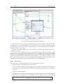
10 GUI
10.1 Domain loading and unloading . . . . .
10.2 Manipulating graph . . . . . . . . . . .
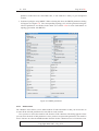
10.3 Creating topologies . . . . . . . . . . .
10.3.1 File menu . . . . . . . . . . . .
10.3.2 Actions menu . . . . . . . . . .
10.3.3 Models menu . . . . . . . . . .
10.3.4 Mode menu . . . . . . . . . . .
10.3.5 Constraints menu . . . . . . . .
10.4 Using traffic matrices . . . . . . . . . .
10.4.1 Synthetic traffic generation . . .
10.4.2 Intra TM generation from BGP .
10.5 MPLS routing . . . . . . . . . . . . . .
10.5.1 Adding a primary LSP . . . . .
10.5.2 Adding a detour Lsp . . . . . .
10.5.3 Computing a fullmesh . . . . .
10.6 IP routing . . . . . . . . . . . . . . . .
10.6.1 Traffic switching . . . . . . . .
10.6.2 Viewing paths . . . . . . . . . .
10.6.3 ECMP Analysis . . . . . . . . .
10.7 Optimal routing . . . . . . . . . . . . .
10.8 Optimizing link Weight with IGP-WO .
10.9 Executing a scenario . . . . . . . . . .
10.10Console . . . . . . . . . . . . . . . . .
10.11SAMTE . . . . . . . . . . . . . . . . .
10.12What-if scenario . . . . . . . . . . . . .
.
.
.
.
.
.
.
.
.
.
.
.
.
.
.
.
.
.
.
.
.
.
.
.
.
.
.
.
.
.
.
.
.
.
.
.
.
.
.
.
.
.
.
.
.
.
.
.
.
.
.
.
.
.
.
.
.
.
.
.
.
.
.
.
.
.
.
.
.
.
.
.
.
.
.
.
.
.
.
.
.
.
.
.
.
.
.
.
.
.
.
.
.
.
.
.
.
.
.
.
.
.
.
.
.
.
.
.
.
.
.
.
.
.
.
.
.
.
.
.
.
.
.
.
.
.
.
.
.
.
.
.
.
.
.
.
.
.
.
.
.
.
.
.
.
.
.
.
.
.
.
.
.
.
.
.
.
.
.
.
.
.
.
.
.
.
.
.
.
.
.
.
.
.
.
.
.
.
.
.
.
.
.
.
.
.
.
.
.
.
.
.
.
.
.
.
.
.
.
.
.
.
.
.
.
.
.
.
.
.
.
.
.
.
.
.
.
.
.
.
.
.
.
.
.
.
.
.
.
.
.
.
.
.
.
.
.
.
.
.
.
.
.
.
.
.
.
.
.
.
.
.
.
.
.
.
.
.
.
.
.
.
.
.
.
.
.
.
.
.
.
.
.
.
.
.
.
.
.
.
.
.
.
.
.
.
.
.
.
.
.
.
.
.
.
.
.
.
.
.
.
.
.
.
.
.
.
.
.
.
.
.
.
.
.
.
.
.
.
.
.
.
.
.
.
.
.
.
.
.
.
.
.
.
.
.
.
.
.
.
.
.
.
.
.
.
.
.
.
.
.
.
.
.
Copyright 2004, 2007 - ULg, UCL
.
.
.
.
.
.
.
.
.
.
.
.
.
.
.
.
.
.
.
.
.
.
.
.
.
.
.
.
.
.
.
.
.
.
.
.
.
.
.
.
.
.
.
.
.
.
.
.
.
.
.
.
.
.
.
.
.
.
.
.
.
.
.
.
.
.
.
.
.
.
.
.
.
.
.
.
.
.
.
.
.
.
.
.
.
.
.
.
.
.
.
.
.
.
.
.
.
.
.
.
.
.
.
.
.
.
.
.
.
.
.
.
.
.
.
.
.
.
.
.
.
.
.
.
.
.
.
.
.
.
.
.
.
.
.
.
.
.
.
.
.
.
.
.
.
.
.
.
.
.
.
.
.
.
.
.
.
.
.
.
.
.
.
.
.
.
.
.
.
.
.
.
.
.
.
.
.
.
.
.
.
.
.
.
.
.
.
.
.
.
.
.
.
.
.
.
.
.
.
.
.
.
.
.
.
.
.
.
.
.
.
.
.
.
.
.
.
.
.
.
.
.
.
.
.
.
.
.
.
.
.
.
.
.
.
.
.
.
.
.
.
.
.
.
.
.
.
.
.
.
.
.
.
.
.
.
.
.
.
.
.
.
.
.
.
.
.
.
.
.
.
.
.
.
.
.
.
.
.
.
.
.
.
.
.
.
.
.
.
.
.
.
.
.
.
.
.
.
.
.
.
.
.
.
.
.
.
.
.
.
.
.
.
.
.
.
.
.
.
.
.
.
.
.
.
.
.
.
.
.
.
.
.
.
.
.
.
.
.
.
.
.
.
.
.
.
.
.
.
.
.
.
.
.
.
.
.
.
.
.
.
.
.
.
.
.
.
.
.
.
.
.
.
.
.
.
.
.
.
.
.
.
.
.
.
.
.
.
.
.
.
.
.
.
.
.
.
.
.
.
.
.
.
.
.
.
.
.
.
.
.
.
.
.
.
.
.
.
.
.
.
.
.
.
.
.
.
.
.
.
.
.
.
.
.
.
.
.
.
.
.
.
.
.
.
.
.
.
.
.
.
.
.
.
.
.
.
.
.
.
.
.
.
.
.
.
.
.
.
.
.
.
.
.
.
.
.
.
.
.
.
.
.
.
.
.
.
.
.
.
.
.
.
.
.
.
.
.
.
.
.
.
.
.
.
.
.
.
.
.
.
.
.
.
.
.
.
.
.
.
.
.
.
.
.
.
.
.
.
.
.
.
.
.
.
.
.
.
.
.
.
.
.
.
.
.
.
.
.
.
.
.
.
.
.
.
.
.
.
.
.
.
.
.
.
.
.
.
.
.
.
.
.
.
.
.
.
.
.
.
.
.
.
.
.
.
.
.
.
.
.
.
.
.
.
.
.
.
.
.
.
.
.
.
.
.
.
.
.
.
.
.
.
.
.
.
.
.
.
.
.
.
.
.
.
.
.
.
.
.
.
.
.
46
46
47
47
47
47
47
47
47
47
48
48
49
49
49
49
49
50
50
50
50
51
.
.
.
.
.
.
.
.
.
.
.
.
.
.
.
.
.
.
.
.
.
.
.
.
.
56
56
57
58
58
59
60
61
61
61
62
62
63
63
65
66
66
68
68
68
69
69
69
71
71
71
- CONTENTS
Page 4 of 82
10.13Creating Charts . . . . . . . . . . . . . . . . . . . . . . . . . . . . . . . . . . .
10.14Using CBGP . . . . . . . . . . . . . . . . . . . . . . . . . . . . . . . . . . . .
11 Traffic matrix generation using NetFlow traces
11.1 Required data formats and file/directory structures . . . . . . . . . . . . . . . .
11.1.1 BGP information . . . . . . . . . . . . . . . . . . . . . . . . . . . . .
11.1.2 NetFlow traces . . . . . . . . . . . . . . . . . . . . . . . . . . . . . .
11.2 Traffix matrix generation steps . . . . . . . . . . . . . . . . . . . . . . . . . .
11.2.1 Generating domain BGP information from BGP dump . . . . . . . . .
11.2.2 Creating inter-domain traffic matrix from NetFlow . . . . . . . . . . .
11.2.3 Generating intra-domain traffic matrix from inter-domain traffic matrix
11.3 Scenario events . . . . . . . . . . . . . . . . . . . . . . . . . . . . . . . . . .
A Summary of xml element and attribute types
Copyright 2004, 2007 - ULg, UCL
.
.
.
.
.
.
.
.
72
73
75
75
75
75
76
76
76
76
77
78
- 1 INTRODUCTION
Page 5 of 82
1 Introduction
Today the usual way of providing a suitable level of service in an enterprise intranet or an Internet
Service Provider is to overprovision the network with respect to the real needs. With the increase
in bandwidth demand, this approach is less and less tenable economically. An alternative way is to
deploy traffic engineering techniques. However, most of the problems that are encountered in this
field are combinatorial and of large size, which implies to find efficient and near optimal heuristics.
We would like to set up an open source toolbox of traffic engineering methods called TOTEM1
that would federate many independent software pieces. The resulting toolbox is expected to include more functionality than existing commercial ones, and is clearly designed to be open, i.e.
incrementally extensible.
This guide presents how to use the TOTEM toolbox and what is needed to know in order to deal
with it. The traffic engineering methods can be classified along several axes: intra-domain versus
inter-domain, IP versus (G)MPLS, on-line versus off-line, or centralized versus distributed. They
are suitable for network optimization, better routing of traffic for providing QoS, load balancing,
protection and restoration in case of failure, etc.
The design of the toolbox also considers different possible use cases. For example, it can be
deployed as an on-line centralized tool in an operational network, or used off-line as an optimization tool or as a traffic engineering simulator. Section 2 describes how to easily install and compile
the toolbox. Sections 3 and 4 describe the XML format that can be used to represent a network
topology and a traffic matrix respectively. Section 5 and 6 describes how to use MPLS and Diffserv in the toolbox. Section 7 describes the tools designed to use the toolbox in a real network
environment. Section 8 presents the algorithms that are already included in the toolbox. Section 9
presents how to use the toolbox without having to write Java code (the scenario XML interface).
Section 10 describes the functionnalities of the GUI and how to use it. Section 11 describes how
to use the toolbox to generate Traffic Matrix files from netflow data.
1
About the TOTEM project : http://totem.info.ucl.ac.be
Copyright 2004, 2007 - ULg, UCL
- 2 GETTING STARTED...
Page 6 of 82
2 Getting started...
The toolbox comes in two archives : a binary one with a precompiled toolbox and a source one
with all the Java sources. These archives contain the following directories :
• dist contains the executable JAR (Java Archive File) totem-<version>.jar (only
for binary package)
• documentation contains this UserGuide
• example contains examples of topology, traffic matrix and scenario
• licence contains the licence of the third libraries
• lib contains the libraries needed to compile and execute the toolbox
• src contains the source code (only for source package)
Currently, the toolbox has been tested only on linux platforms.
2.1 Installation
To use the toolbox, you need a Java Virtual Machine 2 (J2SE 5.0 or newer). If you haven’t a Java
Virtual machine you have to download and install it. Don’t forget to set the JAVA_HOME environment variable to your JVM installation directory.
Decompress the TOTEM archive with
tar -xzvf totem-<version>.tar.gz
With the binary archive, the installation is finished. You can go to section 2.3 to briefly see
how to use the toolbox. With the source release, you need to compile the toolbox as described in
the next section.
2.2 Compilation
The source archive contains all the Java source files and you need to compile them before running the toolbox. To compile the toolbox, we need Ant 3 (release 1.6.2 or newer) provided by the
Apache project. Ant is a Java-based build tool. It is kind of tool like Make. If you haven’t Ant
installed, download and install it. Don’t forget to set the ANT_HOME environment variable.
The Ant build file (build.xml) contains the following interesting targets :
• build builds the TOTEM project
• clean cleans the project and prepares the directory
• doc generates the javadoc in doc directory
2
3
http://java.sun.com/j2se/1.5/
http://ant.apache.org/bindownload.cgi
Copyright 2004, 2007 - ULg, UCL
- 2 GETTING STARTED...
Page 7 of 82
By using :
ant clean build
You compile and build the whole toolbox in the dist/totem-<version>.jar file. If
you compile for the first time the toolbox, you need to call ant clean to create the needed
directories. More information can be found in the README file.
2.3 The "totem.sh" command
This shell script runs the toolbox setting the maximum heap size to 512Mb. The following options
are available to the command line. If no option is set, the GUI will be launched (see section 10).
-demo. Launch the GUI with increased font size (so that it can be projected for a live demo).
-s <scenario.xml> [stopOnError]. Executes the scenario scenario.xml (see section 9 for more information about scenarios). If stopOnerror is true, the scenario will stop
executing after the first errror. In the example directory, you can see some scenarios examples highlighting the main functionalities of the toolbox 4 .
-dir <dirname>. Executes all the scenario files contained in the directory dirname.
-validate <file.xml> [<schemaLocation>]. Validates the XML file file.xml.
schemaLocation is optional (if not present, the validator uses the schema specified in
the XML file).
-gs <type> -f <scen.xml> -d <domain.xml> -t <tm.xml> -m <method>.
Generates a scenario XML file scen.xml using the XML domain file domain.xml and
the XML traffic matrix file tm.xml. The generated scenario depends on type which can
be wca or fullmesh.
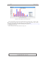
wca generates a scenario which simulates the failure of each link and displays the resulting
load. If wca scenario is chosen, an additional parameter which is -c <chartname> can
be added. If specified, a chart will be created in the file chartname in eps, jpg or png
format depending on the given file extension.
fullmesh generates a scenario which establishes a full mesh of LSPs. The method used to
route the traffic is given by method which can be CSPF, CSPFInvFreeBw, CSPFHopCount,
CSPFInvCap, CSPFTEMetric and DAMOTE.
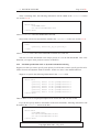
For example, the following command line
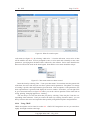
./totem.sh -s examples/abilene/scenario/CSPF-fullmesh.xml
execute the scenario file CSPF-fullmesh.xml of the directory examples/abilene/scenario. This
scenario computes an LSP between each nodes with a reservation corresponding to the demand
given by TM0-abilene.xml using CSPF. At the end, it displays the bandwidth reservation on each
links. This scenario has been generated using ./totem.sh -gs fullmesh.
4
You can find more example files on the toolbox web page (http://totem.run.montefiore.ulg.ac.be/).
Copyright 2004, 2007 - ULg, UCL
- 3 A STANDARD XML FORMAT FOR A NETWORK TOPOLOGY REPRESENTATION
Page 8 of 82
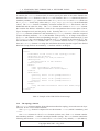
3 A standard XML format for a network topology representation
In this section, we will explain the XML format we defined to represent network topology information. We have chosen the XML language because it is widely used and many tools exist for
dealing with this language. We have created an XML Schema[1] 5 . The schema allows us to
validate a domain file so that we are sure that an XML instance satisfies the data structure we have
defined.
3.1 Description of the XML network representation format
The root element of the XML file is the domain element. It contains five sub-elements: info,
topology, mpls, igp and bgp. The topology and the info elements are mandatory. In
this document, by default, all the elements and attributes are optional except when the contrary is
specified. We decided to separate the information into sections for a clarity and ease of use reason.
So, for example, if an algorithm only needs topology and igp information, it may just not care
about the mpls and the bgp section... The domain element has two attributes : a name (string)
and an ASID (integer). The ASID attribute is mandatory.
The info element contains all the extra information about the topology, including the units in
use. The topology element contains all the information about the topology seen at the network
layer (IP level). So it is a set of nodes and links. The mpls element is composed of a list of lsp
elements. The igp element contains all the information of the intra-domain routing protocol. And
finally, the bgp element contains all the information of the inter-domain routing protocol.
<domain name="domain_test" ASID="1234">
<info>
...
</info>
<topology>
...
</topology>
<mpls>
...
</mpls>
<igp>
...
</igp>
<bgp>
...
</bgp>
</domain>
Table 1: Example of the XML DOMAIN element usage.
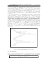
3.1.1 The info element
The info element contains all the extra information about the topology. It contains the following
sub-elements : title (string), date (date), author (string) and description (a string).
5
http://totem.run.montefiore.ulg.ac.be/Schema/Domain-v1_3.xsd
Copyright 2004, 2007 - ULg, UCL
- 3 A STANDARD XML FORMAT FOR A NETWORK TOPOLOGY REPRESENTATION
Page 9 of 82
It contains also a units element which is used to specify the units of the values found in the
document. The units element is a list of unit sub- elements. One unit element only has two
mandatory attributes : type (which can be either delay or bandwidth) and value (which can
be ns, µs, ms, s for the delay values and bps, kbps, mbps, gbps or tbps for the bandwidth
values). The units element is mandatory and must contain two unit sub-elements, one for
bandwidth and the other for delay. The info element also contains a diff-serv element
that contains the Diffserv information, which is the correspondance between the pairs (Classes
Types, Preemption level) and the priority levels. Formally, the diff-serv element is a list of
priority elements (minimum 1 and maximum 8 priority elements) which are composed
of three mandatory attributes : an id (the identifier of the priority, i.e. an integer in the interval
[0,7]), a ct (the identifier of the corresponding class type, i.e. an integer in the interval [0,7]) and
a preemption (the corresponding preemption level, i.e. an integer in the interval [0,7]). The
last sub-element of the info element is the srlgs element which is a list of srlg elements (at
least one). A srlg element is a string (the information about the physical origin of the Shared
Risk Link Group) and has one mandatory id attribute which is an integer).
<info>
<title>This is the title of the topology</title>
<date>2005-02-16</date>
<author>University of Lie</author>
<description>
The description of this domain
</description>
<units>
<unit type="delay" value="ms"/>
<unit type="bandwidth" value="kbps"/>
</units>
<diff-serv>
<priority id="0" ct="0" preemption="0"/>
<priority id="1" ct="0" preemption="1"/>
<priority id="2" ct="1" preemption="0"/>
<priority id="3" ct="1" preemption="1"/>
</diff-serv>
<srlgs>
<srlg id="241">information about this SRLG</srlg>
</srlgs>
</info>
Table 2: Example of the XML INFO element usage.
3.1.2 The topology element
The topology element contains all the information about the topology seen at the network layer
(IP level). So it is a set of nodes and links.
The topology element is composed of two sub-elements : nodes (which is mandatory) and
links.
One nodes element is a list of node elements (at least one). Each node element contains
one mandatory attribute : id which is an unique identifier (string). The node element contains the
following sub-elements : status which can be UP or DOWN (UP by default), rid (IP address),
Copyright 2004, 2007 - ULg, UCL
- 3 A STANDARD XML FORMAT FOR A NETWORK TOPOLOGY REPRESENTATION
Page 10 of 82
description (string), type which can be CORE, EDGE, NEIGH or VIRTUAL, location
(which contains two mandatory float attributes : latitude and longitude) and finally an
interfaces element which is a list of interface elements (at least one). An interface
element has one mandatory id attribute (string which is (locally) unique). An interface element contains the following sub-elements : status which can be UP or DOWN (UP by default),
ip which is an IP address and has a mandatory mask attribute (IP mask of the form X.X.X.X/Y,
Y is in [0, 32])
One links element is a list of link elements (at least one). Each link element contains
one mandatory attribute : id which is a unique identifier (string). A link joins two nodes and
more precisely, two interfaces on two nodes. So a link must have from and to sub-elements
which point respectively to the source interface and to the destination interface. A from element
has two attributes : node (string, the identifier of the source node) which is mandatory and if
(string, the identifier of the interface on the source node). A to element has three attributes :
as (integer, the AS number of the destination node, which is used for inter-domain links), node
(string, the identifier of the destination node) which is mandatory and if (string, the identifier
of the interface on the destination node). A link element can also contain the following subelements : status which can be UP or DOWN (UP by default), description (string), type
which can be INTRA, ACCESS, PEERING, INTER or VIRTUAL, bw which is the bandwidth of
the link (float), technology (string), delay which is the delay of the link (float) and srlgs
which is a list of srlg elements. An srlg element is an integer (the identifier of the SRLG the
link belong to).
<topology>
<nodes>
<node id="router1.foo.net">
<rid>10.0.0.1</rid>
<interfaces>
<interface id="10.0.2.0/30">
<ip mask="10.0.2.0/30">10.0.2.1</ip>
</interface>
</interfaces>
</node>
...
</nodes>
<links>
<link id="1 -> 2">
<from if="10.0.2.0/30" node="10.0.0.1"/>
<to if="10.0.2.0/30" node="10.0.0.2"/>
</link>
...
</links>
</topology>
Table 3: Example of the XML TOPOLOGY element usage.
3.1.3 The mpls element
The mpls element is composed of a list of lsp elements (at least one). An lsp element is
composed of the following sub-elements : path (which is mandatory), bw which is the bandwidth
Copyright 2004, 2007 - ULg, UCL
- 3 A STANDARD XML FORMAT FOR A NETWORK TOPOLOGY REPRESENTATION
Page 11 of 82
demand of the LSP (float), metric which is the metric of the LSP (a float), max_rate which
is the maximal bandwidth rate of the LSP (a float), diff-serv and backup. An lsp element
also has a mandatory attribute id which is the identifier of the LSP (a string).
A path element is a list of at least one link sub-element which is the identifier of a link
(string).
A diff-serv element contains the following mandatory sub-elements : ct (the identifier
of the corresponding class type, i.e. an integer in the interval [0,7]) and preemption which has
two mandatory attributes : setup and holding which are the setup and holding preemption
levels, i.e. an integer in the interval [0,7].
The backup element must be present if the LSP is a backup LSP. This element has one mandatory attribute type, a string that can be DETOUR_LOCAL (for a local detour LSP), DETOUR_E2E
(for an end-to-end detour LSP) or BYPASS (for a local bypass LSP). The backup element has the
following sub-elements : protected_lsp (string) which contains the identifier of the protected
lsp (in case of detour LSP) and protected_links which is mandatory and is composed of a
list of protected_link elements (at least one). A protected_link element is a string
which is the identifier of the link that is protected by the LSP. In case of local protection, the list
should contain the protected link and in case of end-to-end protection, the list should contain all
the links of the primary path.
<mpls>
<lsp id="LSP1">
<path>
<link>1 -> 2</link>
<link>2 -> 3</link>
</path>
<bw>155000</bw>
</lsp>
...
</mpls>
Table 4: Example of the XML MPLS element usage.
3.1.4 The igp element
The igp element contains all the information of the intra-domain routing protocol. The type
attribute specify the running routing protocol (string that can be ISIS or OSPF). The igp element
contains a list of link elements (at least one). One link element contains all the link state
information that is transmitted by the intra-domain routing protocol. The id attribute (mandatory)
of the link element is a string that contains the identifier of the link to which the information is
related. One link element contains two sub-elements : static and dynamic.
The static element contains the following sub-elements : metric (the IGP metric of the
link, a float), te-metric (the Traffic-Engineering metric, also a float), mrbw (maximum reservable bandwidth, a float), mbw (maximum bandwidth, a float), admingroup (integer) and finally
diff-serv. One diff-serv element contains the following sub-elements : bcm which is
mandatory and contains the bandwidth constraint model, a string that can be either MAM (Maximum Allocation Model) or RDM (Russian Doll Model)6 , and a list of bc elements (at least one).
6
this feature is not already supported by the toolbox.
Copyright 2004, 2007 - ULg, UCL
- 3 A STANDARD XML FORMAT FOR A NETWORK TOPOLOGY REPRESENTATION
Page 12 of 82
One bc element contains a float (which is the value of the bandwidth constraint) and a mandatory
attribute id (integer) which identifies to what the bandwidth constraint is related (in MAM, it is
related to one Class Type).
The dynamic element contains one mandatory sub-element : rbw (for Reservable BandWidth). The rbw element is a list of between 1 and 8 (inclusive) priority elements. One
priority element has one mandatory attribute id (which is an integer in the interval [0,7] and
should correspond to a priority defined under the diff-serv element of the info element) and
contains a float which is the reservable bandwidth associated with this priority.
The reservable bandwidth is dynamic in the sense that it can vary with the time (when a new
LSP is established on the link, for example).
<igp type="IS-IS">
<links>
<link id="1 -> 2">
<static>
<metric>20050.0</metric>
<te-metric>50.0</te-metric>
<mrbw>2488320.0</mrbw>
<mbw>2488320.0</mbw>
</static>
<dynamic>
<rbw>
<priority id="0">2488320.0</priority>
<priority id="1">2488320.0</priority>
<priority id="2">2488320.0</priority>
<priority id="3">2488320.0</priority>
</rbw>
</dynamic>
</link>
...
</links>
</igp>
Table 5: Example of the XML IGP element usage.
3.1.5 The bgp element
The bgp element contains the information related to the inter-domain routing protocol, BGP. The
bgp element is thus the place where nodes existing in the topology element will be defined
as BGP routers. This is also the place one defines the BGP sessions between the BGP routers as
well as the IP prefixes to be advertised outside the domain. An example of the XML BGP element
usage is shown in Table 6.
Basically, the bgp element is a sequence of BGP router definitions. Each BGP router is
encoded in a router element which is composed of many attributes. The router is identified
by a mandatory id attribute whose value is a free-form string of characters. There is currently a
single uniqueness constraint on the id attribute. That is there cannot exist two routers that share
the same value of the id attribute.
In addition to this, the router element also has a mandatory rid attribute which represents
the router-ID. This rid attribute is an IP address that identifies the BGP router in the BGP protoCopyright 2004, 2007 - ULg, UCL
- 3 A STANDARD XML FORMAT FOR A NETWORK TOPOLOGY REPRESENTATION
Page 13 of 82
<bgp>
<routers>
<router id="router1.foo.net">
<rid>10.0.0.1</rid>
<networks>
<network prefix="10.0.1/24"/>
</networks>
<neighbors>
<neighbor ip="10.0.0.2" as="666"/>
<neighbor ip="10.0.0.3" as="666"/>
</neighbors>
</router>
...
</routers>
</bgp>
Table 6: Example of the XML BGP element usage.
col. Usually, the router-ID is taken as the highest IP address of the router or as the loopback of the
router. In the toolbox, we will assume that the value of the rid attribute corresponds to the rid
of the corresponding node element in the topology section.
Then, comes the definition of the networks that this router will advertise through the BGP
protocol. The networks are defined in a networks element which is a sequence of network
elements. Each network element contains a single CIDR prefix. This CIDR prefix has the form
of a dotted IP address followed by a slash (“/”) followed by a mask length. The networks
element is optional and can be omitted if no network is originated by this router. However, if a
networks element is present, it cannot be empty. That is, it must contain at least a network
element.
Finally, the router also contains a list of neighbors, i.e. a list of other BGP neighbors with
which it has BGP sessions. The list of neighbors is defined with a neighbors element which
is a sequence of neighbor elements. Each neighbor represents a single BGP neighbor and
has several attributes. Two attributes are used to identify the neighbor: an IP address and an AS
number. The IP address is specified using the ip element. It represents the router-ID of the
neighbor router. The AS number is specified using the as element. It represents the AS number
of the neighbor router. This AS number can be the same as the local router if both routers share an
internal (iBGP) session or they are different if both routers share an external (eBGP) session.
The neighbor element also makes possible the definition of BGP filters. This part is however
still in development and the form that will be given to these filters is not yet precisely defined.
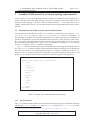
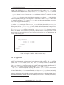
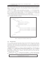
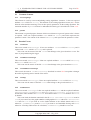
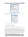
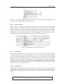
3.2 Example
In table 7, we present an example of the very simple network of figure 1.
0
0_0−>1_0
1
Figure 1: An example simple topology
Copyright 2004, 2007 - ULg, UCL
- 3 A STANDARD XML FORMAT FOR A NETWORK TOPOLOGY REPRESENTATION
Page 14 of 82
<?xml version="1.0" encoding="UTF-8"?>
<domain ASID="1234">
<info>
<title>Test Topology</title>
<date>2005-01-31</date>
<author>RUN - University of Liege</author>
<description>
TOTEM Project (http://totem.info.ucl.ac.be/)
</description>
<units>
<unit type="bandwidth" value="kbps"/>
<unit type="delay" value="ms"/>
</units>
</info>
<topology>
<nodes>
<node id="0">
<location latitude="5" longitude="7"/>
<interfaces>
<interface id="0">
</interface>
</interfaces>
</node>
<node id="1">
<location latitude="44" longitude="1"/>
<interfaces>
<interface id="0">
</interface>
</interfaces>
</node>
</nodes>
<links>
<link id="0_0->1_0">
<from node="0" if="0"/>
<to node="1" if="0"/>
<bw>200000</bw>
<delay>1.4</delay>
</link>
</links>
</topology>
</domain>
Table 7: Example of an XML domain file.
Copyright 2004, 2007 - ULg, UCL
- 4 A STANDARD XML FORMAT FOR A TRAFFIC MATRIX
REPRESENTATION
Page 15 of 82
4 A standard XML format for a traffic matrix representation
We have defined an XML format for intra and inter-domain traffic matrices.
• An intra-domain traffic matrix is associated with a domain, and represents the traffic in this
domain. For example, the traffic matrix expresses the fact that there is traffic of X Mbps
between node A and node B (both nodes A and B belonging to the particular domain, the
traffic enters the domain at node A and exits the domain at node B).
• An inter-domain traffic matrix is also associated with a domain, but traffic is not defined
as going from a node A to a node B inside the domain. Traffic is defined as arriving on
a specific domain node and coming from a source prefix to a certain destination prefix.
These informations are precious for inter-domain traffic engineering. If one wants to map
such an inter-domain traffic matrix to the corresponding intra-domain traffic matrix, one
already knows the node where the traffic enters, but one has to find the egress node for each
destination prefix. It is possible for example to use the C-BGP simulator included in the
toolbox.
We have created an XML Schema defining our XML traffic matrix representation format 7 .
The root element is TrafficMatrixFile which is composed of two elements : info
(optional) and either intraTM either interTM (choice, mandatory).
The info element is composed of the following sub-elements : title (string), date
(dateTime), duration (double) expressed in minutes, author (string), description
(string) and units. The units element is composed of one (and only one) sub-element
unit. The unit element has two mandatory attributes : type (which is contrained to be
bandwidth) and value which can be bps, kbps, mbps, gbps or tbps.
The intraTM element is composed of a list of src elements and has one mandatory ASID
attribute (int). One src element has one mandatory id attribute (string which specifies to
which source node the value is related to) and is composed of a list of dst elements. A dst
element contains a non-negative float value (the traffic from the source node src to the destination node dst) and has one mandatory id attribute (string which identifies the destination
node).
The interTM element is composed of a list of node elements and has one mandatory ASID
attribute (int). One node element has one mandatory id attribute (string which identifies
the node in the domain) and is composed of a list of src elements. A src element has one
mandatory attribute prefix (which identifies the source prefix from where data is coming) and
is composed of a list of dst elements. A dst element contains a non-negative float value
(the bandwidth from the source prefix src to the destination prefix dst) and has one mandatory
attribute prefix (which identifies the destination prefix where data is going to).
Here is an example of the XML TrafficMatricFile element usage (intra-domain traffic
matrix) :
<TrafficMatrixFile>
<info>
< d a t e >2004−10−14T 0 1 : 0 3 : 0 0 < / d a t e >
<units>
< u n i t ty p e =" bandwidth " v a l u e=" kbps " / >
</ units>
</ info>
< I n tr aTM ASID= " 1234 " >
< sr c id="0">
7
http://totem.run.montefiore.ulg.ac.be/Schema/TrafficMatrix-v1_2.xsd
Copyright 2004, 2007 - ULg, UCL
- 4 A STANDARD XML FORMAT FOR A TRAFFIC MATRIX
REPRESENTATION
Page 16 of 82
< d s t i d = " 1 " >37< / d s t >
< d s t i d = " 2 " >23< / d s t >
...
</ src>
< s r c id =" 1 ">
< d s t i d = " 0 " >17< / d s t >
< d s t i d = " 2 " >69< / d s t >
...
</ src>
...
< / I n tr aTM >
</ TrafficMatrixFile>
Here is an example of the XML TrafficMatricFile element usage (inter-domain traffic
matrix) :
<TrafficMatrixFile>
<info>
< d a t e >2004−10−14T 0 1 : 0 3 : 0 0 < / d a t e >
<units>
< u n i t ty p e =" bandwidth " v a l u e=" kbps " / >
</ units>
</ info>
< I n ter TM ASID= " 1234 " >
< n o d e i d = " n o d e1 " >
< s r c p r e f i x =" 1 3 1 . 1 3 0 . 0 . 0 / 1 6 ">
< d s t p r e f i x = " 1 5 0 . 2 1 4 . 0 . 0 / 1 6 " >37< / d s t >
< d s t p r e f i x = " 2 0 2 . 1 3 . 4 . 0 / 2 3 " >23< / d s t >
...
</ src>
< / n o d e>
...
< / I n ter TM >
</ TrafficMatrixFile>
Copyright 2004, 2007 - ULg, UCL
- 5 MPLS ROUTING
Page 17 of 82
5 MPLS routing
This section describes some of the features of the MPLS routing capabilities of TOTEM.
5.1 Bandwidth Sharing
When loading a domain, you can choose to use bandwidth sharing or not. If you choose so,
bandwidth will be shared among LSPs that are not activated at the same time (primary-backup
sharing and backup-backup sharing, see [2]). However, Diffserv is not compatible with bandwidth
sharing. If you decide to use bandwidth sharing, only one class type must be defined in the domain
or an exception will be thrown. Even if multiple preemption levels are defined in the class type,
those levels will be ignored and preemption will never occur.
Copyright 2004, 2007 - ULg, UCL
- 6 DIFFSERV SUPPORT
Page 18 of 82
6 Diffserv support
Diffserv [3] support is implemented into the toolbox. If you don’t want to use Diffserv, you just
have to avoid putting Diffserv fields in the different XML files, and to never use the Java methods
which specify a priority level.
6.1 Current state of Diffserv support
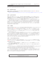
We implemented basic Diffserv-aware TE support into the toolbox and in particular the MAM
(Maximum Allocation Model) bandwidth constraints model [4]. Other bandwidth constraints models will perhaps be implemented in the future. We now give some brief explanations about MAM.
If you would like to have more information, see [4]. Suppose we have a certain number of categories of services (called Class-Types or CTs) and the same number of associated bandwidth
constraints (BCs). MAM states that
Reserved_Bandwith(CTc ) ≤ BCc
(1)
What we call a priority level in this document is in fact a Traffic Engineering Class (TEC), i.e.
a combination of a CT and a preemption priority allowed for that CT. During admission control on
a link for a reservation at priority (TEC) i, all we have to check is that the unreserved bandwidth
at priority i (stored in the toolbox database) is larger than the bandwidth requested by this reservation. This unreserved bandwidth per priority level is the data that should be advertised in IGP link
state packets.
We also implemented a basic preemption support inside CTs.
6.1.1 Conventions
It is always considered that a higher numerical value corresponds to less priority traffic, i.e. traffic
from CT 0 should correspond to more important traffic than traffic from CT 1. And traffic with
preemption level 0 has more priority than traffic with preemption level 1.
6.2 Default behaviour
We will explain here the behaviour you can expect from the Diffserv manager integrated into the
toolbox when specifying some Diffserv fields in domain XML files.
6.2.1 No Diffserv fields in domain XML files
If you don’t need Diffserv support, do not put any diff-serv fields into the <info> field of
the domain XML file (see section 3.1.1). However note that the following information will be
added automatically
<diff-serv>
<priority id="0" ct="0" preemption="0"/>
</diff-serv>
under the <info> element.
Copyright 2004, 2007 - ULg, UCL
- 6 DIFFSERV SUPPORT
Page 19 of 82
Then, concerning links, the following information will be added in the <static> section
(see section 3.1.4)
<diff-serv>
<bcm>MAM</bcm>
<bc id="0">bandwidth</bc>
</diff-serv>
where bandwidth is the total bandwidth of the link.
Some fields will also be automatically added in the <dynamic> section (see section 3.1.4)
<rbw>
<priority id="0">bc_id_0</priority>
</rbw>
where bc_id_0 is the value of the bandwidth constraint (bc) with id 0.
Thus the reservable bandwidth at the unique priority 0 is set the link bandwidth. This is the
behaviour you expect when you don’t want to use Diffserv.
6.2.2 Info field specified but static or dynamic information missing
Suppose now that you want to specify some priority levels but don’t want to specify specific information for static and dynamic fields of all links. In this case, here is the default behaviour.
Suppose we specify the following information in the <info> field.
<diff-serv>
<priority
<priority
<priority
<priority
<priority
<priority
</diff-serv>
id="0"
id="1"
id="4"
id="5"
id="6"
id="7"
ct="0"
ct="0"
ct="1"
ct="1"
ct="1"
ct="1"
preemption="0"/>
preemption="1"/>
preemption="0"/>
preemption="1"/>
preemption="2"/>
preemption="3"/>
Thus we have 2 CTs: 2 accepted preemption levels for the first and 4 for the second.
If you do not specify Diffserv information in the static link fields, following information will
be added in the <static> section of the link.
<diff-serv>
<bcm>MAM</bcm>
<bc id="0">bandwidth/2</bc>
<bc id="1">bandwidth/2</bc>
</diff-serv>
Copyright 2004, 2007 - ULg, UCL
- 6 DIFFSERV SUPPORT
Page 20 of 82
One constraint is thus defined for each CT, and their value is equal to the maximum reservable
bandwidth divided by the number of CTs.
Dynamic information is set accordingly.
<rbw>
<priority
<priority
<priority
<priority
<priority
<priority
id="0">bc_id_0</priority>
id="1">bc_id_0</priority>
id="4">bc_id_1</priority>
id="5">bc_id_1</priority>
id="6">bc_id_1</priority>
id="7">bc_id_1</priority>
</rbw>
Note that if you choose to specify some BC values for some links, dynamic information will
also be set according to the values you specified.
6.2.3 Adding a reservation
Suppose you want to establish an LSP of priority i (i.e. a couple of CT and preemption level) with
reservation b. You have to check for each link in the path the unreserved bandwidth for this priority
level is bigger than b. If it is, you can add this reservation. Now, you may want to not specify a
priority (this parameter being often optional). In this case the considered priority level is the least
priority existing one (i.e. least priority CT, and in this class type, lowest preemption level).
6.3 Preemptions
A basic preemption mechanism had been developed to allow preemption inside CTs. With this
basic mechanism, preemption will never occur between CTs. In fact, preemption between CTs
can be useful only if the following condition holds true, which is not of common use.
X
BCc > M ax_Reservable_Bandwidth
(2)
c
Here is how the preemption mechanism works :
• Lowest preemption levels are looked first for LSPs to preempt.
• If only one LSP can be preempted at least preemption level to free enough bandwidth, it is
preempted.
• If not, arbitrary LSPs of least preemption levels are preempted.
Preempted LSPs are removed from the domain.
Copyright 2004, 2007 - ULg, UCL
- 7 ON-LINE TOOLS
Page 21 of 82
7 On-line tools
7.1 Socket Interface
7.1.1 Description
The TOTEM toolbox can execute events sent from a remote place through a socket interface. In
this mode, the toolbox acts as a server and processes events coming from another machine on
the network. Once a client is connected, it can send XML scenario events to the toolbox which
executes them before returning a result.
For example the socket interface can be used online in a network for path computation :
LSPCreation events are sent to the server which will respond by sending the computed path.
7.1.2 Message format
The messages that the clients should send consist of XML scenario events described in section 9.
However it is important to note that for implementations reasons a single event sent through the
socket interface must be written in only one text line.
Once the event has been executed by the toolbox, a response message is sent back to the client.
The response message is also always transmitted in only one text line. It has the following format
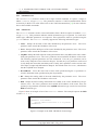
(shown here in multiple lines for readability):
<result>
<command>
...
</command>
<output>
<object>
...
</object>
<message>
...
</message>
</output>
<status>
...
</status>
<exceptions>
...
</exceptions>
</result>
The command element is a copy of the XML event sent by the client. The output element
contains two subelements: object and message. These are respectively a representation of
an object and a text message both related to the execution of the event. The text message is the
same message that is written on standard output when the event is executed locally. For example,
if a LSPCreation event is correctly executed, the object will be the XML representation of the
new LSP and the message will be a string representation of the new LSP path followed by a list of
preemped LSP ids. Note that both subelements are optional.
The status element can be either OK or FAILED depending on the success of the event
execution. If the status is FAILED, the event was not correctly executed because of an exception.
Copyright 2004, 2007 - ULg, UCL
- 7 ON-LINE TOOLS
Page 22 of 82
The exception is then described in the exceptions element. In this case, it contains one (or
more) subelement(s) of the following form:
<exception class="...">
...
</exception>
The class attribute correspond to the class of the exception and the content of the exception
element is the message of the exception.
7.1.3 How to use it
The toolbox socket interface can be started either by means of a scenario event, either in the GUI.
The corresponding scenario event is startScenarioServer. An example of a scenario that
starts the server is LSPComputationServer.xml located in the examples directory of the
root TOTEM folder.
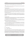
To start the server from the GUI, click on the Start server item under the Scenario
menu. The result of every event executed from the remote place will be visible in the GUI.
The toolbox is also shipped with a simple client. This client sends a complete scenario to a
toolbox running the socket interface. It takes three mandatory command line arguments (host, port
and filename) and one optional (delay). The client establishes a connection with the given host on
the given port, reads the scenario given by its filename and sends it to the server one event at a
time. If delay is also given, the client will wait a certain time between each event.
To build the client, use the specific ant task:
ant build-socketclient
The jar file containing the client is then located in dist/socketclient.jar under the
TOTEM root folder. You can start the client by using the script socketclient.sh.
7.2 Loading a domain from network
7.2.1 Description
TOTEM can be feeded with a domain that comes from network. This feature was originally
developed to allow network discovery tools to feed the toolbox with a real domain.
In this operational mode, TOTEM acts as a client and it connects to a topology server. Once the
server is ready, it sends a topology to the toolbox. The topology is loaded as it is being received.
Note that the domain must be in the TOTEM XML format (see section 3).
7.2.2 How to use it
A domain can be loaded from a remote place either by using the corresponding scenario event
(loadDistantDomain event), either by using the GUI (use "Load Topology from network"
under the "File" menu). In both cases, the server host and port should be provided. If no server
is present at the given host and port, this will result in an execution error. If the server is present,
the connection will be established and TOTEM will start waiting for the topology to be received.
A simple topology server is provided as an example. It is located in the class TopologyServer
in the be.ac.ulg.montefiore.run.totem.core package. This server sends a given
topology file to a TOTEM toolbox instance that connects to it. It has two mandatory arguments:
the port on which to listen for new connections and the filename from which to read the topology.
To build the server, use the specific ant task:
Copyright 2004, 2007 - ULg, UCL
- 7 ON-LINE TOOLS
Page 23 of 82
ant build-toposerver
The jar file containing the server is then located in dist/toposerver.jar under the
TOTEM root folder. You can start the server by using the script toposerver.sh.
Copyright 2004, 2007 - ULg, UCL
- 8 ALGORITHMS ALREADY PRESENT IN THE TOOLBOX
Page 24 of 82
8 Algorithms already present in the toolbox
8.1 Shortest Path First algorithm
The toolbox contains a flexible implementation of the SPF algorithm and its constrained extension
CSPF. The implementation is very efficient and uses a priority queue to store the list of temporary
visited nodes. For computing the path of a LSP with a given reservation, the CSPF skips links that
do not meet the bandwidth requirement. The scenario section explains in more detail how to use
the CSPF to compute a LSP with the toolbox. Differents metrics can be used by the CSPF:
• IGP metric given in the topology (called CSPF)
• IGP TE metric given in the topology (called CSPFTEMetric)
• the inverse of the link capacity (called CSPFInvCap)
• the inverse of the reservable bandwidth (called CSPFInvFreeBw)
• 1 for each link (called CSPFHopCount)
Each different CSPF method has a name (between parentheses) used by the scenario to identify
which metric to use.
Note that the implementation allows the efficient computation of all the paths from a particular
source to all the destinations or from all the sources to a particular destination.
The CSPF implementation is also able to compute backup paths. These calculated backup
paths can be either local or global, link disjoint or node disjoint. CSPF has specific parameters for
local backup computation. These are useless for global backup.
• mergePointLocation Can be "nearest" or "farthest". Indicates where the the local
backup should merge with the primary path.
• mergePointPriority Can be "cost" or "location". Indicates if the path should be cost
minimal among all possible merging point location or if the parameter mergePointLocation
has the priority.
• stopOnError Can be true or false. If a local backup can’t be computed, the other computed backups are returned if true, else an error condition occurs.
8.2 DAMOTE
We will first begin by introducing DAMOTE itself, and then see which additional parameters can
be passed to corresponding scenario events to deal with the power of DAMOTE.
DAMOTE (Decentralized Agent for MPLS Online Traffic Engineering) provides two main
basic functionalities:
• QoS-based routing of Diffserv LSPs (Label Switched Paths) under constraints.
• Local and global detour (backup) LSP routing for fast restoration
Let us review both of them.
The first main function of DAMOTE is to compute primary paths at ingress nodes, in a way
similar to the classical CSPF (Constraint Shortest Path First). This means that all edge nodes will
Copyright 2004, 2007 - ULg, UCL
- 8 ALGORITHMS ALREADY PRESENT IN THE TOOLBOX
Page 25 of 82
compute and set up the "best" path for any given LSP for which they are the ingress. This computation requires that ingress nodes have enough information about all link states in the network.
This is usually achieved by using extensions of link-state routing protocols like OSPF-TE or ISISTE, which flood the network regularly with updated link-states.
Although similar in principle to CSPF, our scheme generalizes it in several ways. While CSPF
is a simple SPF on a pruned topology, obtained by removing links that have not enough capacity to
accept the new LSP, DAMOTE can perform much clever optimizations based on a network-wide
score function. Examples of such functions are: load balancing, hybrid load balancing (where
long detours are penalized), pre-emption-aware routing (where LSP reroutings are penalized).
DAMOTE is generic in the sense that this score function is a parameter of the algorithm. Like in
CSPF, constraints can be taken into account, but here again the constraints can be parameterised
quite freely. Typical constraints refer to the available bandwidth on links per class type (CT), or
to pre-emption levels. For example, it is possible to specify that an LSP of a given CT can only
be accepted on a link if there is enough unreserved bandwidth for this CT by counting only the
resources reserved by LSPs at higher pre-emption levels. This allows us to pre-empt other LSPs if
needed. In that case, DAMOTE can also calculate the "best" subset of LSPs to pre-empt.
DAMOTE can also compute local detour LSPs for fast rerouting. In our approach, each primary can be protected by a series of detour LSPs, each of them originating at the node immediately
upstream of any given link on the primary path. Those detour LSPs thus protect the downstream
node (if possible) or the downstream link and merges with the primary LSP anywhere between
the protected resource (exclusive) and the egress node (inclusive). Those many LSPs have to be
pre-established for fast rerouting in case of failure, and provisioned with bandwidth resource. In
terms of bandwidth consumption, this scheme is only viable if detour LSPs are allowed to share
bandwidth among themselves or with primary LSPs, which is what we have achieved. The main
idea is that we assume that at most one link or node will fail at the same time in the network. Under
this assumption, we can share bandwidth between LSP that will never be activated together.
We will now explain which additional parameters can be passed to corresponding scenario
events to deal with the power of DAMOTE.
8.2.1 Starting DAMOTE
DAMOTE can be started using the startAlgo scenario event (see 9.8.3). If backup LSPs need
to be calculated and bandwidth sharing is a desirable feature, the domain must be loaded with
bandwidth sharing enabled (see loadDomain scenario event 9.2.5).
By default, DAMOTE is configured with a hybrid score function (load balancing with traffic
minimization contribution). But DAMOTE can also use pure load balancing score function, delayoriented score function, min-hop routing,. . . Let us review the available options.
Pure load balancing score function
DAMOTE can first be used with a pure load balancing score function, which is the following:
2
X L(i,j)
L
−
ω cap (i, j) ω cap
(i,j)∈U
Copyright 2004, 2007 - ULg, UCL
- 8 ALGORITHMS ALREADY PRESENT IN THE TOOLBOX
with
Page 26 of 82
L(i,j)
1 X
L
=
cap
cap
ω
|U |
ω (i, j)
(i,j)∈U
the mean of the relative link load throughout the network. This function is then the variance on the
relative link load and, as such, represents the deviation from the optimal load balancing situation.
In a perfectly balanced network, this deviation would be zero for all links so that all would be
occupied in exactly the same proportions.
To use DAMOTE with a pure load balancing score function, you must set parameter “loadBal”
to 1 and parameter “tMin” to 0 within the StartAlgo event.
Hybrid load balancing score function
The main problem with the load-balancing function presented above is that the only thing it tries
to do is to flatten the relative load throughout the network. It will not matter if some of the paths go
a long way around in order to achieve a better load-balancing. We must then try to limit the length
of the paths chosen for the LSPs by adding a kind of "shortest path length" term to the objective
function.
Our "traffic minimization" term is the sum of the square relative link loads,
X L(i,j) 2
ω cap (i, j)
(i,j)∈U
As a consequence, the compromise between load balancing and traffic minimization can be expressed as follows
2
X L(i,j) 2
X L(i,j)
L
+ tM in ∗
−
loadBal ∗
ω cap (i, j) ω cap
ω cap (i, j)
(i,j)∈U
(i,j)∈U
The (weighted) combination of both terms will give more importance to the load-balancing
term if the deviation is high enough to justify the detour, else it will let the "shortest path" term
minimize the resources used.
By default, DAMOTE is configured with “loadBal” equals to 2 and “tMin” equals to 1. You
can change freely these two parameters.
Delay-oriented score function
Another available objective function is an average delay objective function
X
1
cap
ω (i, j) − L(i,j)
(i,j)∈U
P
Since, for a packet size P , ωcap (i,j)−L
approximates the queuing and transmission delay
(i,j)
on link (i, j), optimizing this function will strive to minimize the average delay throughout the
network. This will naturally lead to load-balance the network. Moreover, this objective has a
built-in traffic minimization feature in the sense that long paths would degrade the average delay
and are therefore discouraged.
To use this objective function, you must set “loadBal” to 0, “tMin” to 0 and “delay” to 1.
Shortest-path score function
Finally, if you want to use min-hop routing, you can set “loadBal” to 0, “tMin” to 0 and “load” to
1.
Copyright 2004, 2007 - ULg, UCL
- 8 ALGORITHMS ALREADY PRESENT IN THE TOOLBOX
Page 27 of 82
8.2.2 Computing a primary path with DAMOTE
An LSP can be computed with DAMOTE using the LSPCreation scenario event (see 9.3.8.
When computing an LSP, you can pass an additional parameter to DAMOTE called preempt
(boolean). This parameters tells DAMOTE whether it can preempt LSPs to establish the new one.
In this case, DAMOTE returns a list of LSPs to preempt, and immediately deletes them from its
own database. These LSPs are also removed from the toolbox database itself. Diffserv parameters
can also be passed, but note that DAMOTE does not correctly support preemption when multiple
categories of services (CTs) are used (to be fixed in the future). If you plan to use preemption,
please only specify one category of service and several preemption levels for this category of service.
Additionnal note on preemption levels and categories of service
The default library (lib/libdamote.so) included in the release supports up to eight preemption levels
and eight class types. If speed is a main concern for you and if you are using DAMOTE in
a single class type and single preemption level environnement, you should link libdamote.so to
libdamote11.so (instead of libdamote88.so) in order to increase speed perforcalculatemance.
8.2.3 Computing backups paths with DAMOTE
Detour LSPs can be created with the scenario event LSPBackupCreation. DAMOTE supports
end-to-end and local detour. Corresponding parameters can then be passed to the scenario event.
8.2.4 Restrictions
Inside TOTEM, as bandwidth sharing is not compatible with Diffserv (see section 5.1), DAMOTE
cannot be used to calculate backup paths when multiple priority levels are used.
Moreover, DAMOTE should be used to calculate backups only when bandwidth sharing is
enabled. Otherwise, DAMOTE may return a backup path for which bandwidth is shared with
other lsps; so it is possible that there is not enough free bandwidth to establish this lsp in TOTEM
(as bandwidth sharing does not occur). In fact, an exception will be thrown if you try to compute
a backup path without bandwidth sharing enabled.
8.3 MIRA
This section describes how to use the MIRA implementation included in the toolbox. This algorithm can be used to compute LSPs between two nodes of the network. In that sense, the use of
this algorithm is quite similar to the use of CSPF algorithm.
Two MIRA algorithms are integrated in the TOTEM Toolbox : NEWMIRA (described in [5])
and Simple MIRA (SMIRA, described in [6]). These algorithms are both based on the principle
of Minimum Interference Routing. When you start the algorithm, it is needed to specify which
algorithm you want to use. In order to specify which algorithm you want to use, you have to add a
param XML element whose name is “version” and the value is either “NEWMIRA” or “SMIRA”.
By default, SMIRA is used.
The MIRA algorithms make distinction between “EDGE” nodes and “CORE” nodes. “EDGE”
nodes can be LSPs extremity while “CORE” nodes can only be intermediate nodes. If the node
type is not set, the node is considered as “EDGE”. Report to section 3.1.2 to see how to define the
node type in the topology file.
A example of scenario using MIRA can be found in
examples/simpleDomain/Scenario/create_lsp_mira.xml.
Copyright 2004, 2007 - ULg, UCL
- 8 ALGORITHMS ALREADY PRESENT IN THE TOOLBOX
Page 28 of 82
8.4 SAMCRA
This section describes how to use the SAMCRA implementation included in the toolbox. This
algorithm can be used to compute LSPs between two nodes of the network. Once again, the use
of this algorithm is quite similar to the use of CSPF algorithm.
SAMCRA is an exact multi-constrained shortest path algorithm that was originally proposed
in [7] and later extended in [8]. The implementation of SAMCRA included in the toolbox is the
one described in [8].
To use SAMCRA, you have first to start the algorithm (called XAMCRA) precising the QoS
constraints you desire and the version of the algorithm (till now only SAMCRA is included, but
we plan to integrate other algorithm of the X-AMCRA familly). Once started, you can compute a
path using this algorithm precising the QoS constraint for the desired path. If one QoS constraint
that was desired is not provided, we assume ∞ for this constraint (i.e. no constraint) and if one
constraint is provided for a parameter that was not desired, it is discarded.
When starting the algorithm, you can use the following boolean parameters : useDelay,
useMetric and useTEMetric. The bandwidth constraint is allways used. When routing a
LSP using LSPCreation element, you can use the following routing parameters : DelayConstraint, MetricConstraint and TEMetricConstraint to specify corresponding
constraints. The bandwidth constraint is included in the addLSP element.
You can find an example of scenario file using SAMCRA in
examples/abilene/Scenario/XAMCRA-fullmesh.xml.
8.5 optDivideTM
This algorithm consists of dividing the traffic matrix into N sub-matrices, called strata, and route
each of these independently. We can use two different implementations of this method in routers.
The method can also be used to compute a very precise approximation of the optimal value of
a given objective function for comparison to heuristic Traffic Engineering algorithms. For this
application, the algorithm is very efficient on large topologies compared to an LP formulation.
More information about this algorithm can be found in paper [9].
You can find an example of scenario file using optDivideTM in
examples/abilene/Scenario/optDivideTM.xml.
8.6 CBGP
C-BGP is a BGP routing solver. It aims at computing the interdomain routes selected by BGP
routers in a domain. The route computation relies on an accurate model of the BGP decision
process [10] as well as several sources of input data. The model of the decision process takes
into account every decision rule present in the genuine BGP decision process as well as the iBGP
hierarchy (route-reflectors). More information on how C-BGP works can be obtained from the
C-BGP web site [11].
The input data required by C-BGP includes intradomain and interdomain information. First,
the knowledge of the interdomain routes learned through BGP from the neighbor domains is required. This information can be obtained from MRT [12] dumps collected on the genuine BGP
routers or it can be introduced manually. The route computation also relies on the knowledge
of the intradomain structure. Indeed, the BGP decision process relies at some point on the IGP
weight of the interdomain paths from ingress to egress routers to perform its route selection. This
is often related to as the hot-potato routing rule. For this purpose, C-BGP also contains a model of
the intradomain routing relying on shortest-path computation. The intradomain structure knowledge is obtained from the TOTEM XML topology. Finally, C-BGP needs to be told what must
Copyright 2004, 2007 - ULg, UCL
- 8 ALGORITHMS ALREADY PRESENT IN THE TOOLBOX
Page 29 of 82
be computed through a simulation scenario. See Section 9 for more information on the scenario
events that are currently available in the TOTEM toolbox.
The C-BGP algorithm is available in the toolbox through the CBGP class in the package
be.ac.ucl.ingi.totem. C-BGP currently provides the following functionnalities within
the TOTEM toolbox. First, when the C-BGP algorithm is started (see Section 9.8.3), it builds an
internal representation of the domain being considered from the TOTEM XML topology which
was previously loaded. This includes building a model of the domain’s network based on the
topology element. The intradomain model built by C-BGP currently only takes into account
the nodes, links and IGP weights found in the nodes and igp. It does not model the multiple
interfaces of one node. Nor does it model multiple links between a pair of nodes.
The internal representation of the domain also contains a model of BGP routing. This includes
nodes that are modelled as BGP routers and the BGP sessions that are established between the
BGP routers. This information is also obtained from the TOTEM XML topology, within the bgp
element (see Section 3.1.5).
Then, C-BGP makes possible running the path computation and later extracting information
on the path computation results. Running the path computation requires calling the int simRun()
method. In order to extract the paths selected by C-BGP, the following methods are provided:
• Vector netNodeGetRT(String sNodeAddr, String sPrefix)
This method returns the content of the routing table of the node identified by sNodeAddr.
The sNodeAddr is a string that contains the IP address of the node. The sPrefix arguments
permits retrieving only the routes that match the given prefix. The sPrefix contains a CIDR
prefix in the form “address / mask length”.
• Vector bgpRouterGetRib(String sRouterAddr, String sPrefix)
This method returns the content of the BGP routing information base (RIB) of the BGP
router identified by sRouterAddr. The sRouterAddr is a string that contains the IP address
of the router. The sPrefix arguments permits retrieving only the routes that match the given
prefix. The sPrefix contains a CIDR prefix in the form “address / mask length”.
• Vector bgpRouterGetAdjRib(String sRouterAddr, String sNeighborAddr, String sPrefix, boolean bIn)
This method returns the content of the BGP routing adjacent information bases (Adj-RIBs)
of the BGP router identified by sRouterAddr. The sRouterAddr is a string that contains the
IP address of the router. The sNeighborAddr argument specifies the IP address of the peer
corresponding to the requested Adj-RIB. The sPrefix arguments permits retrieving only the
routes that match the given prefix. The sPrefix contains a CIDR prefix in the form “address
/ mask length”. The bIn argument controls which Adj-RIB is requested. If bIn is true, the
input Adj-RIB is returned. Otherwise, the output Adj-RIB is returned.
In order to load interdomain routes in C-BGP, the Java class provides the following method:
int bgpRouterLoadRib(String sRouterAddr, String sFileName). This method loads the content
of the specified MRT dump file into the BGP router identified with the sRouterAddr argument.
The MRT file must be provided uncompressed in ASCII format. Use the route_btoa conversion
tool provided with the MRTd routing toolkit [12] for this purpose.
A convenient way to call C-BGP commands from the TOTEM toolbox is to rely on the int
runCmd(String sCommand) method. The command takes a single argument, sCommand, which
is a string containing a C-BGP command. If it is a valid C-BGP command, it is executed.
Many additional methods are provided, but not yet documented. Please refer to C-BGP’s
documentation [11] and C-BGP’s Java classes for more details.
Copyright 2004, 2007 - ULg, UCL
- 8 ALGORITHMS ALREADY PRESENT IN THE TOOLBOX
Page 30 of 82
8.7 IGP-WO
IGP-WO (Interior Gateway Protocol-Weight Optimization) module aims at finding a link weight
setting in the domain for an optimal load balancing. It provides a routing scheme adapted to the
traffic demand matrix for congestion avoidance. The main inputs to the IGP-WO module are:
• Network topology: routers (nodes), links (arcs), link capacities
• Traffic demand matrix: source, destination, demand (bandwidth)
• Number of iterations: total number of iterations used in the heuristic search
• Maximum weight value (Wmax ): maximum weight value that can be assigned to links
The program yields an output as the weights for the links in the network. Here are some
remarks regarding the current version of the tool.
• Multiple path routing: The traffic is assumed to be split equally among all of the shortest
paths.
• A special objective function is used. Each link is assigned a function, which is convex
and piecewise linearly increasing with the total load on the link. The main objective is to
minimize the sum of these functions over all the links. For the definition of the function, see
[13] or [14].
Since the problem of finding the optimal weight setting is NP-hard (no efficient algorithm
available), a heuristic algorithm is applied to find a good but not necessarily optimal solution
[14]. The algorithm is based on a well-known heuristic technique, called tabu search [15], whose
attributes are summarized as follows:
• Solution representation: The solution is represented as a vector of weights. The weights are
restricted to be integers in the range of [1, Wmax ].
• Neighborhood structure: Two types of neighborhood search are carried out.
– Single weight change: The weight of a randomly selected link is changed.
– Evenly balancing flows: Given a destination node (t), another node (u) is selected
randomly among the ones that are on any shortest path toward t. The weights of the
arcs outgoing from u is adjusted in such a way that the traffic from u to t is shared
among multiple arcs. The weight change is restricted to the arcs which have less load
than a threshold. The changes leading infeasible weight values are also avoided.
• Tabu lists: Tabu lists are used in tabu search to avoid cycling during the whole run. In order
to save memory and time, special hash functions are utilized in IGP-WO.
• Diversification: Diversification is carried out when the working solution is not improved for
300 iterations. During the diversification, each link weight is changed with a probability
rate 10% by adding a randomly chosen integer between [−2, +2]. If the resulting weight is
infeasible (less than 1 or larger than Wmax ), it is forced to the corresponding bound value.
• Neighborhood Sampling: At each iteration, a proportion of the neighborhood is evaluated
due to the large size of the problems. The initial rate by which the neighborhood is sampled
is determined by the users. During the algorithm run, the value of the sampling rate is
updated. If the current solution is improved, the sampling rate is divided by three, if not it is
multiplied by two. The upper and lower bounds of the sampling rate are determined by the
users, too.
Copyright 2004, 2007 - ULg, UCL
- 8 ALGORITHMS ALREADY PRESENT IN THE TOOLBOX
Page 31 of 82
The main IGP-WO algorithm is written in C and integrated through JNI. The IGPWO class is
located in the package be.ac.ucl.poms.repository.IGPWO. The following method
is provided by IGP-WO:
T o t e m A c t i o n L i s t c a l c u l a t e W e i g h t s P a r a m e t e r s ( i n t ASID , i n t [ ] TMID ,
i n t n u m _ i t e r s , i n t w_max , i n t r a n d o m _ i n i t i a l , i n t s e e d ,
d o u b l e m i n _ s a m p _ r a t e , d o u b l e m ax _ sam p _ r ate , d o u b l e i n i t _ s a m p _ r a t e ,
double [ ] i n i t i a l W e i g h t s ) throws Exception
where ASID and TMID represent the domain and traffic matrix idenditification numbers. IGPWO supports multiple traffic matrices. In case of multiple traffic matrices, the algorithm minimizes
the sum of objective functions over the given traffic matrices.
num_iters ans w_max is the number of iterations and maximum possible weight value, respectively. random_initial determines whether the initial solution of the algorithm is created
randomly, or is assigned to the currently used weights in the network. seed (default 0) is used
for the random number generator. min_samp_rate, max_samp_rate, init_samp_rate
control the sampling rate during the algorithm run. The sampling rate is not allowed not to go
behind min_samp_rate and max_samp_rate.
The default value for the number of iterations is set to 150. The default value is kept low for
the small example problems in the toolbox. If you have a large problem, it is suggested to assign a
higher value to num_iters. The run time of the program increases with the number of iterations.
The default value for w_max is set to 50. The maximum value that can be given to w_max is
65535. The authors of the program suggest not to give a very large value for w_max. As the value
increases, the output weights become less user-friendly and the running time increases due to the
computations necessary for hash table values.
The default values for min_samp_rate, max_samp_rate, init_samp_rate are 0.01,
0.4 and 0.2, respectively. The running time of the algorithm increases with the sampling rate
control parameters.
8.8 SAMTE
TOTEM also includes an hybrid IP/MPLS optimization method called SAMTE (Scalable Approach for MPLS Traffic Engineering). The idea of SAMTE is to combine both the simplicity
and robustness of IGP routing and the flexibility of MPLS. This approach lies between the pure
IP metric-based optimization (as IGP-WO) and the full mesh of LSPs. SAMTE uses the simulated annealing meta-heuristic to find a small number of LSPs (given as parameter) to establish in
the network. The combination of the set of LSPs computed by SAMTE and the IGP routing for
remaining flows optimise a given operational objective.
To use SAMTE, you first have to generate a Candidate Path List using the samte:generateCPL scenario element. This element accept the following parameters nbPath (the number of
path to generater per source destination pair of nodes), maxDepth (the maximal number of
nodes per path), verbose (print some information while generating the candidate path list)
and fileName which specifies the file where to store the candidate path list. Once you have
a candidate path list (be carefull, this list can take a huge amount of place on your hard disk
!), you can use SAMTE with the scenario event samte:SAMTE. You have to provide the Candidate Path List file with the parameter cplName. You can also specify the number of runs
of the algorithm (nbRun), the number of LSP to establish (nbLSP) and the Traffic Matrix to
use (TMID). The subelement samte:simulatedAnnealing configures the parameters of the
simulated annealing heuristic via the parameters T0 the initial temperature, alpha the cooling
factor, L the size of the plateau and E, ǫ, parameter for the stopping conditions. The subelement of
Copyright 2004, 2007 - ULg, UCL
- 8 ALGORITHMS ALREADY PRESENT IN THE TOOLBOX
Page 32 of 82
samte:simulatedAnnealing is samte:objectiveFunction which specify the used
objective function.
To show the link loads with the established LSPs, you have to use the ShowLinkInfo element with the type set to LOAD_BIS. This means Basic IGP Shortcut. This specifies the traffic
that is routed on each LSP.
An example of use of SAMTE can be found in
examples/abilene/Scenario/samte.xml.
8.9 Multi Commodity Flow
This algorithm tries to solve the routing problem by using a linear programming formulation. It
uses the free program "glpsol" to solve the routing problem. It tries to optimize the maximum link
utilization. The model used is located in the file src/resources/modelAMPL/mcf-min-maxUtil.mod.
You must have the "glpsol" executable in order to use this algorithm.
8.10 Reopt
This algorithm written by Sandford Bessler from FTW8 allows to dimension an LSP. It is written
in AMPL and uses the CPLEX solver. It is based on a MCF problem and uses multiple explicit
paths calculated in advance. The idea of this algorithm is to adapt existing LSPs to new traffic
conditions while minimizing the number of LSP size changes.
You can find more information about this algorithm in [16].
8.11 LSPDimensioning
This algorithm written by Hung Tuan Tran from FTW is an adaptive provisioning algorithm based
on:
1. Traffic load measurements
2. Packet-level target QoS constraint
P (delay > D) < ǫ
(3)
where D is the given delay bound and ǫ the given delay violation probability.
The traffic load is measured in a slot-by-slot manner. A certain number of such measurement
slots constitutes a resizing window. The bandwidth is recalculated and updated (using one of the
four prediction schemes) at the end of each resizing window and the newly assigned bandwidth is
valid for the next resizing window. The algorithm is written in C and was integrated thanks to JNI.
More details about this algorithm can be found in [17].
8.12 ComputeMCNFOptimalRouting
This algorithm computes the optimal routing for an objective function given as an argument, using
the ILOG CPLEX linear programming solver [18]. The available objective function are those cited
in [19], i.e.
• the Fortz objective function. This function can also be optimized using the IGP-WO algorithm (see 8.7 subsection).
8
http://www.ftw.at
Copyright 2004, 2007 - ULg, UCL
- 8 ALGORITHMS ALREADY PRESENT IN THE TOOLBOX
Page 33 of 82
• the MIRA objective function, which minimizes the sum of the max-flows between each pair
of nodes of the network.
• the Blanchy objective function, which takes an alpha parameter. The type of this parameter
is double, and its defalut value is 1.0. This function is the compromise between load
balancing and traffic minimization seen in subsection 8.2.
1
a
• the MeanDelay ( ca −l
) and WMeanDelay ( cal−l
) objective functions. In these cases, piecea
a
wise linear approximations of the functions are computed. The nbInt parameter can be set
to define the number of intervals of this approximation. The defalut value for nbInt is 9.
P
P
• the InvCap ( ua ), MinHop ( la ) and umax (max ua ) objective functions.
P
• the Degrande objective function (CB · umax + CU · ua ), which takes two parameters :
C_B and C_U. Both of these parameters are of type double and their default values are
both 1.0.
The optimization is executed for the default domain, using the traffic matrix given in the scenario file. For each objective function, two formulations of the problem can be used :
1. the Node-Link formulation.
2. the Link-Path formulation. This formulation uses the computeAllDistinctRoute
method to compute the paths between each pair of nodes. The user has to set the nbPaths
argument, which defines the maximum number of paths to be computed for each pair.
An example of scenario using this algorithm can be found in
/examples/abilene/Scenario/cplexMCNF.xml
Since the CPLEX optimizer is not free, the default compiling options don’t build this class.
People who own the CPLEX licence (and thus have the cplex.jar file) can compile it as explained below :
• First add the path to cplex.jar in the MANIFEST.MF file which can be found in the
src/java/be/ac/ulg/montefiore/run/totem/repository/cplexMCNF/
META-INF/ directory :
Class-Path: ../../dist/totem-3.0.jar *PATH_TO_CPLEX*/cplex.jar
• Add a reference to the XML schema in the preferences.xml file located in the src/resources
directory (or in the preferences.xml file under the totem root folder if present). Under
the SCENARIO-SCHEMA-LOCATION key, add the string
http://jaxb.model.scenario.cplexMCNF.repository.totem.run.montefiore.ulg.ac.be
http://totem.run.montefiore.ulg.ac.be/Schema/CPLEX-MCNF-Scenario-v1_0.xsd
and under the SCENARIO-PACKAGES key, add the string
be.ac.ulg.montefiore.run.totem.repository.cplexMCNF.scenario.model.jaxb
separated by a ":" character.
An example of preferences file that has CPLEX enabled is located in /src/resources/cplexMCNF/.
Alternatively you can replace your existing preferences file with this one.
Copyright 2004, 2007 - ULg, UCL
- 8 ALGORITHMS ALREADY PRESENT IN THE TOOLBOX
Page 34 of 82
• Build the toolbox using the following command :
ant clean build
• Then build the plugin :
ant -Dplugin=be/ac/ulg/montefiore/run/totem/repository/cplexMCNF/
-Dplugin.lib=*PATH_TO_CPLEX*/cplex.jar
build-given-plugin
You can ommit the -Dplugin.lib line if the cplex.jar is located in the totem library
directory (totem/lib/java).
Copyright 2004, 2007 - ULg, UCL
- 9 A STANDARD XML FORMAT FOR A SCENARIO REPRESENTATION
Page 35 of 82
9 A standard XML format for a scenario representation
The XML scenario format is very simple: it’s a list of events. There are four super abstract types
that can only be extended: eventType, ASEventType, TMEventType, ASTMEventType.
The first one has only one optional attribute time which specifies when the event has to occur. ASEventType and TMEventType define each an other optional attribute (ASID and
TMID respectively). ASEventType is intended to be extended by intra-domain events, and
TMEventType by traffic-related events. Finally, ASTMEventType combine the two last types.
Note that if ASID is not specified, the events use the default domain and if TMID is not specified,
the events use the default traffic matrix for the specified domain (or for the default domain).
Some events have to point out to files located on the local hard drive (loadDomain, loadTrafficMatrix,
...). By default, the paths are defined relatively to the TOTEM root folder. This default behaviour
can be changed by setting the pathRelativeTo attribute of the scenario element. The value
of this attribute corresponds to the directory from which the relative paths defined in the events
must be interpreted. It is even possible to specify a relative path for this attribute. In this case, the
path is interpreted relatively to the current scenario file path.
For example, if you want to create a scenario that will load a domain that is in the same folder
as the scenario file, you write something like the following.
<scenario pathRelativeTo="./">
<loadDomain file="topology.xml"/>
</scenario>
If you did not specify the pathRelativeTo attribute, TOTEM will look for a file named
topology.xml in its root folder.
Here is an example of a short scenario:
<? xml v e r s i o n = " 1 . 0 " e n c o d i n g = " ISO−8859−1 " s t a n d a l o n e = " y e s " ? >
< !−−
T h i s s c e n a r i o u s e s CBGP t o s i m u l a t e t h e f a i l u r e o f a p e e r i n g s e s s i o n
b e t w e e n A b i l e n e and Geant .
A u t h o r : Bruno Q u o i t i n ( bqu@info . u c l . ac . be )
A u t h o r : Jea n L e p r o p r e ( lep r o p r e@ r u n . m o n t e f i o r e . u l g . ac . be )
−−>
<scenario
x s i : s c h e m a L o c a t i o n = " h t t p : / / j a x b . model . s c e n a r i o . t o t e m . r u n . m o n t e f i o r e . u l g . ac . be
h t t p : / / t o t e m . r u n . m o n t e f i o r e . u l g . ac . be / Schema / S c e n a r i o −v1_1 . x s d
h t t p : / / j a x b . model . s c e n a r i o . t o t e m . i n g i . u c l . ac . be
h t t p : / / t o t e m . r u n . m o n t e f i o r e . u l g . ac . be / Schema / CBGP−S c e n a r i o −v1_0 . x s d "
x m l n s : x s i = " h t t p : / / www. w3 . o r g / 2 0 0 1 / XMLSchema−i n s t a n c e "
x m l n s : c b g p = " h t t p : / / j a x b . model . s c e n a r i o . t o t e m . i n g i . u c l . ac . be "
xmlns = " h t t p : / / j a x b . model . s c e n a r i o . t o t e m . r u n . m o n t e f i o r e . u l g . ac . be " >
<loadDomain f i l e = " e x a m p l e s / a b i l e n e / a b i l e n e . xml " d e f a u l t D o m a i n = " f a l s e "
removeMultipleLinks =" t r u e " / >
< s t a r t A l g o name= "CBGP" / >
<cbgp:CBGPPeerRecv r o u t e r = " 1 9 8 . 3 2 . 8 . 2 0 2 " p e e r = " 6 2 . 4 0 . 1 0 3 . 2 5 3 "
msg= "BGP4 | 0 | A| 1 9 8 . 3 2 . 8 . 2 0 2 | 1 1 5 3 7 | 1 3 0 . 1 0 4 / 1 6 | 2 0 9 6 5 2 6 1 1 | IGP | 6 2 . 4 0 . 1 0 3 . 2 5 3 | 0 | 0 | " / >
<cbgp:CBGPPeerRecv r o u t e r = " 1 9 8 . 3 2 . 8 . 1 9 9 " p e e r = " 1 9 8 . 3 2 . 1 1 . 6 2 "
msg= "BGP4 | 0 | A| 1 9 8 . 3 2 . 8 . 1 9 9 | 1 1 5 3 7 | 1 3 0 . 1 0 4 / 1 6 | 2 0 9 6 5 2 6 1 1 | IGP | 1 9 8 . 3 2 . 1 1 . 6 2 | 0 | 0 | " / >
<cbgp:CBGPPeerRecv r o u t e r = " 1 9 8 . 3 2 . 8 . 1 9 3 " p e e r = " 6 2 . 4 0 . 1 0 3 . 1 6 5 "
msg= "BGP4 | 0 | A| 1 9 8 . 3 2 . 8 . 1 9 3 | 1 1 5 3 7 | 1 3 0 . 1 0 4 / 1 6 | 2 0 9 6 5 2 6 1 1 | IGP | 6 2 . 4 0 . 1 0 3 . 1 6 5 | 0 | 0 | " / >
<cbgp:CBGPRun / >
<cbgp:CBGPInfo i n f o = " AdjRIB " >
<param name= " r o u t e r " > 1 9 8 . 3 2 . 8 . 1 9 3 < / param>
< / cbgp:CBGPInfo >
<cbgp:CBGPInfo i n f o = " AdjRIB " >
<param name= " r o u t e r " > 1 9 8 . 3 2 . 8 . 1 9 9 < / param>
Copyright 2004, 2007 - ULg, UCL
- 9 A STANDARD XML FORMAT FOR A SCENARIO REPRESENTATION
Page 36 of 82
< / cbgp:CBGPInfo >
<cbgp:CBGPInfo i n f o = " AdjRIB " >
<param name= " r o u t e r " > 1 9 8 . 3 2 . 8 . 2 0 2 < / param>
< / cbgp:CBGPInfo >
<cbgp:CBGPInfo i n f o = " R eco r d R o u t e " >
<param name= " s r c " > 1 9 8 . 3 2 . 8 . 2 0 0 < / param >
<param name= " d s t " > 1 3 0 . 1 0 4 . 2 3 0 . 5 4< / param>
< / cbgp:CBGPInfo >
<cbgp:CBGPInfo i n f o = " R eco r d R o u t e " >
<param name= " s r c " > 1 9 8 . 3 2 . 8 . 2 0 1 < / param >
<param name= " d s t " > 1 3 0 . 1 0 4 . 2 3 0 . 5 4< / param>
< / cbgp:CBGPInfo >
<cbgp:CBGPInfo i n f o = " R eco r d R o u t e " >
<param name= " s r c " > 1 9 8 . 3 2 . 8 . 2 0 2 < / param >
<param name= " d s t " > 1 3 0 . 1 0 4 . 2 3 0 . 5 4< / param>
< / cbgp:CBGPInfo >
<cbgp:CBGPPeerDown node = " 1 9 8 . 3 2 . 8 . 1 9 3 " p e e r = " 6 2 . 4 0 . 1 0 3 . 1 6 5 " / >
<cbgp:CBGPRun / >
<cbgp:CBGPInfo i n f o = " R eco r d R o u t e " >
<param name= " s r c " > 1 9 8 . 3 2 . 8 . 2 0 0 < / param >
<param name= " d s t " > 1 3 0 . 1 0 4 . 2 3 0 . 5 4< / param>
< / cbgp:CBGPInfo >
<cbgp:CBGPInfo i n f o = " R eco r d R o u t e " >
<param name= " s r c " > 1 9 8 . 3 2 . 8 . 2 0 1 < / param >
<param name= " d s t " > 1 3 0 . 1 0 4 . 2 3 0 . 5 4< / param>
< / cbgp:CBGPInfo >
<cbgp:CBGPInfo i n f o = " R eco r d R o u t e " >
<param name= " s r c " > 1 9 8 . 3 2 . 8 . 2 0 2 < / param >
<param name= " d s t " > 1 3 0 . 1 0 4 . 2 3 0 . 5 4< / param>
< / cbgp:CBGPInfo >
</ scenario >
Since TOTEM 1.1, it’s possible to plug new scenario events into the toolbox at the runtime. This
slightly complicates the writing of a scenario file but allows the user to really extend the scripting
language defined by the scenarios. In the developer guide, we explain how to write new scenario
events. In this user guide, we will only give some XML notions necessary to write scenario files
at hand9 .
The above scenario file illustrates how to write scenario files which use several schemas. In
this particular scenario, there are two types of events:
• Core events defined in the main scenario schema: loadDomain, startAlgo, etc.
• CBGP-related events defined in a separate schema: CBGPInfo, CBGPPeerDown, etc.
The idea is that the toolbox must know in which schema the events are defined. This is done
thanks to the attributes of the scenario element. There are four attributes:
xmlns:xsi="http://www.w3.org/2001/XMLSchema-instance". This attribute defines a namespace called xsi. In the W3C recommandation about XML namespaces, we
can read: "...An XML namespace is a collection of names, identified by a URI reference
[RFC2396], which are used in XML documents as element types and attribute names...".
The URI of a namespace has no special meaning, this is just a way to give a unique name to
the namespace. However, as in our case, the URI can be used for a special purpose. Companies often use it as a pointer to a real Web page where you can find information about the
namespace. In the toolbox, we use it to identify the package in which the class of an event
is defined (as a package name is supposed to be unique, scenario namespaces will also be
unique). So this attribute defines the xsi namespace. This definition allows us to use the
schemaLocation attribute defined in the xsi namespace.
9
If you use JAXB to write your scenario files, you can just skip all these explanations as JAXB will do the job for
you...
Copyright 2004, 2007 - ULg, UCL
- 9 A STANDARD XML FORMAT FOR A SCENARIO REPRESENTATION
Page 37 of 82
xsi:schemaLocation="http://jaxb.model.scenario.totem.run.montefiore.ulg.ac.be
http://totem.run.montefiore.ulg.ac.be/Schema/Scenario-v1_1.xsd
http://jaxb.model.scenario.totem.ingi.ucl.ac.be
http://totem.run.montefiore.ulg.ac.be/Schema/CBGP-Scenario-v1_0.xsd". In
the
XML Schema Part 0: Primer document, we can read: "...In an instance document, the attribute xsi:schemaLocation provides hints from the author to a processor regarding the location of schema documents. The author warrants that these schema documents are relevant to
checking the validity of the document content, on a namespace by namespace basis..." and
"...The schemaLocation attribute value consists of one or more pairs of URI references, separated by white space. The first member of each pair is a namespace name, and the second
member of the pair is a hint describing where to find an appropriate schema document for
that namespace. The presence of these hints does not require the processor to obtain or use
the cited schema documents, and the processor is free to use other schemas obtained by any
suitable means, or to use no schema at all...". So in this example, we use two namespaces:
http://jaxb.model.scenario.totem.run.montefiore.ulg.ac.be and
http://jaxb.model.scenario.totem.ingi.ucl.ac.be. The first namespace
contains the core elements and the associated schema is located at
http://totem.run.montefiore.ulg.ac.be/Schema/Scenario-v1_2.xsd.
The second namespace contains the CBGP-related elements and the associated schema can
be found at
http://totem.run.montefiore.ulg.ac.be/Schema/CBGP-Scenariov1_0.xsd.
xmlns:cbgp="http://jaxb.model.scenario.totem.ingi.ucl.ac.be". This
attribute indicates that all the elements coming from the http://jaxb.model.scenario.totem.ingi.ucl.ac.be namespace are prefixed with cbgp:. So, as CBGPPeerRecv,
CBGPRun, etc. are defined in
http://jaxb.model.scenario.totem.ingi.ucl.ac.be, they are prefixed with
cbgp:.
xmlns="http://jaxb.model.scenario.totem.run.montefiore.ulg.ac.be".
This attribute indicates which namespace is the default namespace. In this case, this is the
namespace associated with the core elements. It means that in the sequel of the document
all core elements have no prefix. For example, param and loadDomain are core events
defined in
http://jaxb.model.scenario.totem.run.montefiore.ulg.ac.be and have
no prefix.
Currently, there are three scenario XML schemas shipped with the toolbox:
1. Scenario-v1_1.xsd, which contains the core events;
2. CBGP-Scenario-v1_0.xsd, which contains the CBGP events;
3. SAMTE-Scenario-v1_0.xsd, which contains the events used by SAMTE;
We now describe two elements used by many events and all the core events classified by
functions. Then we give more details about the CBGP-related events and the SAMTE-related
events.
Copyright 2004, 2007 - ULg, UCL
- 9 A STANDARD XML FORMAT FOR A SCENARIO REPRESENTATION
Page 38 of 82
9.1 Common elements
9.1.1 routingAlgo
This element is used by events manipulating routing algorithms’ instances. It has one required
attribute name which is a string. This attribute is the routing algorithm’s name (see 8 for the
allowed values and their meaning). You can also specify parameters for the routing algorithm. The
maximum number of param elements is unbounded and their type is described in section 9.1.2.
9.1.2 param
This element is a general purpose element which is used whenever a general "param-value" scheme
is required. It has one required attribute name which is a string and which represents the
parameter’s name. The content of the element is a string and represents the parameter’s value.
9.2 Domain Events
9.2.1 linkDown
This event extends ASEventType. It has two attributes: linkId which is a string and is
required and cause which is a string and is optional.
This event sets the status of the link linkId that belongs to the given domain to DOWN. The
cause is just printed using the logger.
9.2.2 linkMetricChange
This event extends ASEventType. It has two required attributes: linkId which is a string
and metric which is a float.
This event sets the metric of the link linkId that belongs to the given domain to metric.
9.2.3 linkTeMetricChange
This event is the same as linkMetricChange described in section 9.2.2 except that it changes
the traffic engineering metric instead of the metric.
9.2.4 linkUp
This event extends ASEventType. It has one required attribute linkId which is a string.
This event sets the status of the link linkId that belongs to the given domain to UP.
9.2.5 loadDomain
This event extends eventType. It has one required attribute file and three optional attributes
(defaultDomain, useBWSharing and removeMultipleLinks). file is a string
and the three other attributes are booleans. Note that the three booleans attributes are false
by default.
This event loads the domain contained in the file file. removeMultipleLinks must be
true if you want to force the graph to not be a multigraph and false otherwise. defaultDomain must be true if you want to set the loaded domain as the default domain and false
otherwise. useBWSharing must be true if you want to use bandwidth sharing and false
otherwise. If backup LSPs need to be calculated, useBWSharing should be set to true.
Copyright 2004, 2007 - ULg, UCL
- 9 A STANDARD XML FORMAT FOR A SCENARIO REPRESENTATION
Page 39 of 82
9.2.6 nodeDown
This event extends ASEventType. It has two attributes which are strings. The first one is
nodeId which is required and the second one is cause which is optional.
This event sets the status of the node nodeId that belongs to the given domain to DOWN. The
cause is just printed using the logger.
9.2.7 nodeUp
This event extends ASEventType. It has only one required attribute nodeId which is a string.
This event sets the status of the node nodeId that belongs to the given domain to UP.
9.2.8 saveDomain
This event extends ASEventType. It has only one required attribute file which is a string.
This event saves the given domain in the file file.
9.2.9 topologyGeneration
This event extends eventType. It accepts an unbounded number of param elements. The
param element is described in section 9.1.2. It also accepts two optional attributes: type and
path.
This event allows you to use the topology generation capabilities of the toolbox. The type
indicates the topology generator to use. Only BRITE generator is implemented in the toolbox.
The path indicates the path in which to save the generated files.
In order to make the use of this event simple, all the parameters for BRITE generator are
optional and good default values have been defined10 . So, you can simply type
<topologyGeneration />
to generate a topology. We now list in the tables 8 and 9 all the possible parameters and their possible values (you can find more information about the BRITE-specific parameters in the BRITE user manual).
A example scenario (topologyGeneration.xml) is provided in the examples directory.
9.3 Lsp & Routing Events
This section describes the routing events. You’ll find LSP routing events and optimal routing
events. IP routing events are described at section 9.5 under "Display events".
9.3.1 cplex:ComputeMCNFOptimalRouting
In order to use this algorithm, the user has to own an ILOG CPLEX licence and compile the
toolbox as explained in section 8.12.
This event extends ASTMEventType. It has three optional arguments : verbose and
displayTEMetrics which are both of type boolean with default value false, and exportModelToFile
which is a string giving the path to a .lp file where the linear programming model has to be exported.
The name argument of the cplex:objectiveFunction element defines the objective
function to be optimized. It is a string, and is required. The objective functions that can
10
These default values are taken in part from [20].
Copyright 2004, 2007 - ULg, UCL
- 9 A STANDARD XML FORMAT FOR A SCENARIO REPRESENTATION
Page 40 of 82
be optimized are those given in section 8.12, i.e. Fortz, MIRA, Blanchy, MeanDelay,
WMeanDelay, InvCap, umax, Degrande and MinHop.
The eventual parameters of the objective functions are defined in param elements, as shown
below :
<param name="alpha">0.5</param>
The name argument gives the name of the parameter, and its value is defined between the
opening and closing tags.
The formulation element has a required subelement, which can either be nodeLink or
linkPath. In the latter case, the user has to set the value of the nbPaths argument, which is
of type int.
<cplex:formulation>
<cplex:linkPath nbPaths="2"/>
</cplex:formulation>
An example scenario file using this event can be found in
/examples/abilene/Scenario/cplexMCNF.xml
9.3.2 computeMCF
This event extends ASTMEventType. It has also three optional attributes: runGLPSOL, dataFile and resultFile. The two latter attributes are strings and the former is a boolean.
This event runs the MCF algorithm on the given domain and traffic matrix and prints the result
(mean, max, standard deviation and percentile 10) using the logger at the info level. runGLPSOL
must be true if you want to run glpsol and false if you want only to generate the data file.
resultFile is the name of the file that glpsol must produce and dataFile is the name of
the file that glpsol takes as input.
9.3.3 deleteAllLSP
This event extends ASEventType. It deletes all the LSPs established on the specified domain or
on the default domain if no domain is specified.
9.3.4 enableTrafficSwitching
This event extends ASEventType. It enables traffic switching on the specified domain or on
the default domain. When traffic switching is disabled, routing cannot occur on primary lsps for
which some resources are down (nodes, links). When it is enabled, routing can use some of the
pre-established backup lsps to route the traffic (see 9.5.4 to see how traffic can be routed on LSPs).
A example is provided in the file examples/bwSharing/Scenario/trafficSwitching.xml.
9.3.5 IGPWOCalculateWeights
This event extends ASEventType. It has three optional attributes which are ints: maxPossibleWeight, nbIter and seed. It also has an optional attribute called initialWeightArray
which can be CURRENT or RANDOM. The default value for nbIter is 150, 50 for maxPossibleWeight, 0 for seed and RANDOM for initialWeightArray. It also accepts zero or one
samplingRate element and an unbounded number of trafficMatrix elements. These
trafficMatrix elements have only one required attribute TMID that represents the ID of a
Copyright 2004, 2007 - ULg, UCL
- 9 A STANDARD XML FORMAT FOR A SCENARIO REPRESENTATION
Page 41 of 82
traffic matrix. The samplingRate element has three optional attributes which are floats:
initial (default value: 0.2), min (default value: 0.01) and max (default value: 0.4).
This event runs the IGPWO algorithm on the given domain and traffic matrices. nbIter is the
number of iterations that IGPWO must do and maxPossibleWeight is the maximum weight
that IGPWO can produce. seed is used for the random number generator in the algorithm.
The samplingRate element controls the sampling of neighborhoods during local search. At
each iteration, a proportion of the neighborhood is evaluated due to the large size of the problems.
The initial rate by which the neighborhood is sampled is determined by initial. During the
algorithm run, the value of the sampling rate is updated. If the current solution is improved, the
sampling rate is divided by three, if not it is multiplied by two. The upper and lower bounds of the
sampling rate are determined by max and min.
9.3.6 LSPBWChange
This event extends ASEventType. It has two required attributes lspId which is a string and
bw which is a float.
This event sets the reservation of the LSP lspId of the given domain to bw.
9.3.7 LSPBackupCreation
This event extends ASEventType. It has two optional attributes: lspId which is a string
and bw which is a float. It also accepts the following subelements in sequence:
• Detour or Bypass. Exactly one of these two elements must occur exactly one time.
The Detour element has one required attribute protectedLSP which is a string and
two optional attributes (methodType and protectionType). methodType can be
LOCAL or GLOBAL (default value). protectionType can be NODE_DISJOINT (default value) or LINK_DISJOINT. The Bypass element accepts one or several protectedLink elements which have only one required attribute linkId which is a string.
• The routingAlgo element that must occur exactly one time. This element is described
in section 9.1.1 page 38.
This event creates a backup LSP on the specified domain using the specified routing algorithm.
The ID of the newly created LSP will be lspId and its bandwidth will be bw. If these parameters are not specified, default values will be used (an ID will be automatically generated and the
bandwidth will be, for example, the bandwidth of the protected LSP). If the Detour element is
present, a detour LSP will be created. Otherwise, we create a bypass LSP. In the case of a detour
LSP, protectedLSP must be the ID of the LSP to protect, methodType indicates whether
the backup LSP to create must be local (LOCAL) or global (GLOBAL), and protectionType
indicates whether the backup LSP must be node disjoint (NODE_DISJOINT) or link disjoint
(LINK_DISJOINT) from the protected LSP. In the case of a bypass LSP, the linkId attributes
of the protectedLink elements are the IDs of the links to protect.
Important note: do not forget to start the routing algorithm before using it in a LSPBackupCreation event. See the section 9.8.3 for more information.
9.3.8 LSPCreation
This event extends ASEventType. It has two required attributes (src and dst) which are
strings and three optional attributes (lspId, bw and establishLSP). lspId is a string,
bw is a float and establishLSP is a boolean. It also accepts the following subelements in
sequence:
Copyright 2004, 2007 - ULg, UCL
- 9 A STANDARD XML FORMAT FOR A SCENARIO REPRESENTATION
Page 42 of 82
• A metric element that contains a float and that can occur 0 or 1 time.
• A maxRate element that contains a float and that can occur 0 or 1 time.
• A diff-serv element that can occur 0 or 1 time. The content of this element is the same
as the diff-serv element described in section 6.
• A path element that can occur 0 or 1 time. The content of this element specifies the route
of the LSP. It can be described as a sequence of node ids (<node>node_id</node>) or
a sequence of links ids (<link>link_id</link>).
• The routingAlgo element that is optional. This element is described in section 9.1.1
page 38.
This event creates a primary LSP on the specified domain using the specified routing algorithm.
The source of the LSP is src and the destination of the LSP is dst. Its reserved bandwidth is
bw. If bw is not specified, the reserved bandwidth will be 0. lspId is the ID given to the created
LSP (if it is not specified, an ID is automatically generated). metric is the metric of the created
LSP and maxRate is the maximum rate at which it will be possible to send data over the LSP.
For more information about the diff-serv element, see the section 6.
The path element is used to establish explicit route LSPs. If it is present, the element
routingAlgo will be ignored and the LSP will be established following the given route.
The establishLSP attribute, which is true by default, can be set to false in order
to only calculate the LSP route without establishing it. The calculated route will be printed on
standard output.
Important note: do not forget to start the routing algorithm before using it in a LSPCreation
event. See the section 9.8.3 for more information.
9.3.9 LSPDeletion
This event extends ASEventType. It has one required attribute lspId which is a string.
This event deletes the LSP lspId of the given domain.
9.3.10
optDivideTM
This element launch the optDivideTM algorithm (described in section 8.5).
It has four optional attributes: N (an int whose default value is 3), objectiveFunction
which can be equal to MeanDelay, WMeanDelay or NLFortz, establishMultipleFullMesh
which is a boolean and specify if a full-mesh of LSP has to be established or not and finally
verbose (a boolean).
9.4 Traffic matrix Events
9.4.1 generateIntraTM
This event extends eventType. This element requires the following attributes: NETFLOWbasedirectory, NETFLOWdirFileName, BGPbasedirectory, BGPdirFileName, clusterFileName, trafficMatrixFileName, minutes and samplingRate. All these attributes
are strings, except the last two which are ints.
This event is used to generate an intra-domain traffic matrix from BGP dump information and
NetFlow traces. See section 11 for more information about required formats. You will find details
about the parameters in section 11. The minutes and samplingRate parameters are used to
Copyright 2004, 2007 - ULg, UCL
- 9 A STANDARD XML FORMAT FOR A SCENARIO REPRESENTATION
Page 43 of 82
convert flow sizes (in bytes) found in NetFlow traces in kbps. You must fill minutes with the
length (in minutes) of the NetFlow traces period. samplingRate must contain the sampling
rate used in the NetFlow traces.
9.4.2 loadTrafficMatrix
This event extends TMEventType. It has one required attribute file which is a string.
This event loads the traffic matrix contained in the file file. The traffic matrix ID of the
loaded traffic matrix will be the given traffic matrix ID. If you don’t specify an ID, it will be
generated automatically and the matrix will be set as the default traffic matrix.
9.4.3 removeTrafficMatrix
This event extends ASTMEventType. It has no other parameters.
This event removes the traffic matrix from the manager. If the attribute tmId is not provided,
the default traffic matrix is removed.
9.4.4 trafficMatrixGeneration
This event extends ASTMEventType. It accepts an unbounded number of param elements. The
param element is described in section 9.1.2. It also accepts two optional string attributes: path
and type.
The type attribute indicates the type of traffic generator to use. Generators included in the
toolbox are Constant, Gravity or Random.
This event allows you to use the traffic generation capabilities of the toolbox. A traffic matrix
with the specified TMID will be created for the specified domain (if numTrafficMatrices
parameter is 1). In order to make the use of this event simple, all the parameters are optional and
default values have been defined. So, you can simply type
<trafficMatrixGeneration />
to generate a traffic matrix.
We now list in the table 10 all the common parameters and their possible values.
Table 11, 12 and 13 lists model specific parameters for random, gravity and constant generator
respectively.
9.5 Display Events
9.5.1 echo
This event extends eventType. It has one required attribute msg which is a string.
This event prints the string msg on the standard output stream.
9.5.2 ECMPAnalysis
This event extends ASEventType. It accepts no attribute nor element.
This event prints information about existing equal cost paths on the standard output stream.
Note that this event uses the standard metrics (not the TE metrics) of the given domain.
Copyright 2004, 2007 - ULg, UCL
- 9 A STANDARD XML FORMAT FOR A SCENARIO REPRESENTATION
Page 44 of 82
9.5.3 listShortestPaths
This event extends ASEventType. It has five attributes: src, dst and SPFType which are
strings and ECMP and nodeList which are booleans. All these attributes are optional.
This event prints information about shortest paths of the given domain on the standard output
stream. If src and dst are specified, it prints only shortest paths between these two nodes. If
only src (resp. dst) is specified, the shortest paths from src (resp. to dst) to (resp. from) all
the other nodes are listed. If neither is specified, it prints all the shortest paths of the given domain.
If you want to take ECMP into account, ECMP must be set to true and false otherwise (note
that it is false by default). SPFType is exactly the same attribute as the one described in section
9.5.4. Finally, nodeList specifies whether the paths must be printed under the form of a list of
nodes or a list of links. If it is true, a list of nodes is printed. Otherwise, the event prints a list of
links. Note that the attribute is true by default.
9.5.4 ShowLinkInfo
This event extends ASTMEventType. It has four optional attributes type, verbose, ECMP and
SPFtype. type can be LOAD, LOAD_BIS, LOAD_IS, RESERVATION and PRIMARY_BACKUP.
verbose and ECMP are booleans and SPFtype is a string.
This event prints information about the load or about the reservation of links (if the value of
type is LOAD or RESERVATION) on the standard output stream. If type is not specified, it
prints information about the load of links by default. verbose must be true if you want to have
information about each link of the given domain and false if you just want to print the following
values: maximum, mean, standard deviation and percentile 10 (verbose is false by default).
SPFtype allows you to choose the SPF algorithm used to compute the load or the reservation of
links (see the section 8.1 for the possible values). By default, a classical SPF algorithm based on
the links’ metrics is used. If you want to enable ECMP (Equal Cost MultiPath), ECMP must be
true and false otherwise. By default, ECMP is false.
If the value of type is PRIMARY_BACKUP, the event prints some information about primary
and backup link reservation (total primary bandwidth reserved, oversubscription for backup (with
or without taking sharing between primary and backup paths into account), mean and max link
utilization). In order to use this feature correctly, you have to set the useBWSharing attribute of
the loadDomain element to true.
The values LOAD_BIS, LOAD_IS, LOAD_OVERLAY are used when part of the traffic is
routed with IGP routing (shortest path based on link weigths) while other part of the traffic is routed
with MPLS label switched paths. In particular, the values LOAD_BIS and LOAD_IS can be used
for SAMTE (see section 8.8), but can also be used in other algorithms. The value LOAD_BIS
corresponds to the Basic IGP Shortcut model. In this model, the traffic that is forwarded on the
path of an LSP is the whole traffic that crosses the ingress node of the LSP and whose exit point
is the egress of the LSP. The value LOAD_IS is used for IGP Shortcut. In this model, the traffic
that is forwarded on the path of an LSP is the whole traffic that crosses both the ingress and egress
nodes of the LSP. In this last model, more traffic is forwarded on the LSP (there is no restriction
about the exit point of the traffic). Finally, the LOAD_OVERLAY value corresponds to the overlay
model. In this model, the traffic is forwared on a LSP if the source and destination of the traffic
match the ingress and egress of the LSP.
If you want to deal with backup LSPs and link/node failures, you should probably want to enable traffic switching in order for the traffic to be routed on some backup path when a failure is encountered on a primary LSP. Traffic switching can be enabled using the enableTrafficSwitching
event (see section 9.3.4).
Copyright 2004, 2007 - ULg, UCL
- 9 A STANDARD XML FORMAT FOR A SCENARIO REPRESENTATION
Page 45 of 82
9.5.5 ShowLinkReservableBandwidth
This event extends ASEventType. It has two attributes: a string linkId which is required
and an int priority which is optional.
This event prints the reservable bandwidth of the link linkId for the given priority level
on the standard output stream. If priority is not specified, it uses the minimum priority level
of the specified domain.
9.6 Charts Events
It is now possible (since version 2.0) to generate some charts from the data in the toolbox. The
chart creation uses the JFreeChart11 library. An interface has been created to output charts in
graphics files from the scenario XML.
Examples of scenario that use charts can be found in
• example/abilene/Scenario/charts1.xml
• example/abilene/Scenario/charts2.xml
• example/abilene/Scenario/SPF-load-chart.xml
The chart creation process is divided into three parts : selecting the data to collect, collecting
the data and outputting the chart.
Each of these steps refers to a specific scenario event detailed hereunder.
9.6.1 chartCreation
This is the first event to use when willing to create a chart. This event takes one mandatory
attribute id which is the referring name of the chart and has only one mandatory sub-event
(collector). The latter specifies the type of data to collect before the chart can be built. The
attribute name refers to the name of the java class that is used to collect the data. Specifics
parameters can be passed to the collector via an unbounded number of param sub-elements.
For now, there are only two types of chart data collectors : LinksLoadDataCollector and
LinksReservedBWDataCollector. The first one collects the load of each link computed
via a shortest path algorithm and the second one collects the reserved bandwidth of each link. The
parameters that can be passed are the domain on which to collect the data (via the parameter asId)
and whether the load should be taken as relative or not (via the absoluteLoad parameter which
can be true or false). If they are not set, the default domain is taken and relative load is used,
i.e. absoluteload/capacity. Note that both collectors uses the same parameters set.
9.6.2 chartAddSeries
At the moment when this event is executed, data are added to the currently under construction chart. The chart to which to add the data is specified by the chartId attribute. The
seriesName attribute is used to identify the data series. It must have an unique value in a single
chart. It might be used by the plotter as the legend name of the data series. Again, parameters can
be passed to the collector through the collector sub-element. The LinksReservedBWDataCollector takes no parameters when adding data series and the LinksLoadDataCollector
can take up to four parameters (tmId, strategy, routingAlgo and ECMP). These corresponds to IGP routing parameters used to compute the load (see section 10.6). If you do not
11
http://www.jfree.org/jfreechart/
Copyright 2004, 2007 - ULg, UCL
- 9 A STANDARD XML FORMAT FOR A SCENARIO REPRESENTATION
Page 46 of 82
provide some of the parameters, the default value will be used. The default values for these parameters are SPF routing as strategy with CSPF as routing algo and ECMP disabled. The default
traffic matrix will be used when the parameter tmId is not set.
9.6.3 chartSave
When the chart is created and contains some data, it can be output to a file. Note that we did not
specify the type of chart that we want to build, only the chart data is defined at this point.
The chartSave event takes the mandatory attributes chartId, file and format with
obvious mean. The format can be JPG, PNG or EPS. Some other obvious parameters of the chart
must be provided through sub-elements. It is title, xAxisTitle, yAxisTitle, width,
height. The last element that should be provided is the plotter whose name corresponds to a
java class and defines the type of graph to build. Again, specifics parameters can be passed to the
plotter.
For now, three kinds of chart plotters are included in the toolbox: LoadIntervalChartPlotter, DecreasingLineChartPlotter and LoadChartPlotter.
The LoadIntervalChartPlotter take two optional parameter: maxValue and nbInterval, default values are respectively 1 and 10. The interval 0-maxValue is divided in a
number of disjoint sets. For each of these sets, a bar is represented. The height of the bar corresponds to the frequency of the data for the considerated set.
The DecreasingLineChartPlotter takes no parameters. It is used to plot a line graph
where all values in a series are sorted. The plotted point with the highest Y coordinate has the
smallest X coordinate, so that the chart represent a decreasing line.
The LoadChartPlotter takes two parameters: asId and allLinks. The asId parameter has no default value. allLinks is false by default. This plotter creates bar charts using
links loads. The x-axis represents the links and the y-axis represents the (absolute or relative) load.
The plotter has been designed to allow the creation of two different bar charts:
• Charts where the load of all links is displayed
• Charts where only a statistic about the load of links is displayed
The distinction of the two types of charts is made thanks to the allLinks parameter. If it is
true, the first type of charts is created. Otherwise, the second type of charts is created. There is
also a distinction in the meaning of the series names. In the first case, they give the name of the
algorithm used to compute loads. In the second case, they give the links IDs. Finally, for the first
type of plots, a legend will be displayed. This is not the case for the second type of plots. Note
that the asId parameter gives the domain on which the data were collected. If it is not provided,
the default domain is used.
9.6.4 chartDeletion
This event refers to a chart created with chartCreation through the chartId attribute. Use
it to free the resources associated with a chart.
9.7 On-line events
9.7.1 loadDistantDomain
This event takes one required attribute host and one optional attribute port.
Once this event is executed, the toolbox connects to the specified host and port and waits for
an XML domain to be sent. See section 7.2 for more information.
Copyright 2004, 2007 - ULg, UCL
- 9 A STANDARD XML FORMAT FOR A SCENARIO REPRESENTATION
Page 47 of 82
9.7.2 listenToLSPsDemands
This event is deprecated. It was renamed to startScenarioServer.
9.7.3 startScenarioServer
This event starts a server that listens to XML events sent by the network interface (see 7.1). This
must be the last event of the scenario since it won’t return.
This event extends eventType. It has one optional attribute which is the port on which to
listen to. If this attribute is not given, default port will be used (port 1234).
9.8 Other core events
9.8.1 addNetworkController
This event extends ASTMEventType. It has two required attributes name and className
which are strings. It also accepts an unbounded number of param elements.
This event records a new network controller for the specified domain and traffic matrix. The
param elements are used to specify parameters specific to the network controller to record. name
is a unique name identifying the network controller and className is the class name of the
network controller to record.
9.8.2 removeNetworkController
This event extends eventType. It has only one required attribute name that is a string.
This event removes the network controller name if it exists.
9.8.3 startAlgo
This event extends ASTMEventType. It has one required attribute name which is a string. It
also accepts an unbounded number of param elements as subelements.
This event starts the algorithm name on the specified domain and traffic matrix (if the algorithm is independent of one or both of these elements, you are allowed to not specify them).
By means of the param elements, you can specify algorithm-specific parameters to start it. The
available algorithms (and the possible values for name) are given in section 8.
Important note: you always have to start an algorithm before using it. Note that the started
algorithms are automatically stopped when the execution of the scenario is finished.
9.8.4 stopAlgo
This event extends ASTMEventType. It has one required attribute name which is a string.
This event stops the algorithm name on the specified domain and traffic matrix (if the algorithm is independent of one or both of these elements, you are allowed to not specify them). The
available algorithms (and the possible values for name) are given in section 8.
Important note: this event allows the user to reinitialise an algorithm which doesn’t use the
observer design pattern. Other uses of this event must be avoided!
9.9 CBGP Events
In this section, we describe the events related to the C-BGP simulator. These are defined in the
schema available at
http://totem.run.montefiore.ulg.ac.be/Schema/CBGP-Scenario-v1_0.xsd.
Copyright 2004, 2007 - ULg, UCL
- 9 A STANDARD XML FORMAT FOR A SCENARIO REPRESENTATION
Page 48 of 82
9.9.1 CBGPExecute
The CBGPExecute element is used to run a single C-BGP command. It requires a single attribute, command, of type string. The parameter contains a C-BGP command which will be
executed by C-BGP if it is valid. Please refer to the C-BGP documentation [11] for more information on the available commands.
9.9.2 CBGPInfo
The CBGPInfo element is used to extract information from C-BGP. It requires an attribute, info,
of type string. This parameter indicates which information type is requested. For each information type, additional parameters are requested. These parameters must be specified using the
params attribute. The CBGPInfo currently supports the following information types:
• Links : Dumps all the links of the node identified by the parameter router. The router
parameter must contain the IP address of the node.
• Peers : Dumps all the BGP peers of the router identified by the parameter router. The router
parameter must contain the IP address of the router.
• AdjRIB : Dumps the BGP adjacent routing information base (Adj-RIB) of the router identified by the parameter router. The router parameter must contain the IP address of the router.
The following optional parameters are also understood. First, the peer parameter can be
used to only dump the routes related to this peer. Second, the prefix parameter can be used
to only dump the routes that match this prefix. Finally, the in parameter can be used to select
if the input or output Adj-RIB must be dumped. The default value of in is true, which means
that the Adj-RIB-in are dumped.
• RecordRoute : Traces the route from a source node specified using the src parameter towards a destination node specified using the dst parameter.
• RT : Dumps the routing table of the node identified by the parameter router. The router
parameter must contain the IP address of the node.
• RIB : Dumps the BGP routing information base (RIB) of the router identified by the parameter router. The router parameter must contain the IP address of the router. Note, the
optional prefix parameter described in the AdjRIB information type can also be used for the
RIB information type.
Figure 2 shows an example of use of the CBGPInfo element. The example requests the RIB
of router 10.0.0.1.
<CBGPInfo info="RIB">
<param name="router">10.0.0.1</param>
</CBGPInfo>
Figure 2: Example of the XML CBGPInfo element usage.
Copyright 2004, 2007 - ULg, UCL
- 9 A STANDARD XML FORMAT FOR A SCENARIO REPRESENTATION
Page 49 of 82
9.9.3 CBGPLoadRib
The CBGPLoadRib element is used to load BGP routes collected on a genuine BGP router in
C-BGP. The BGP routes are provided in a file whose format is ASCII MRT (see [11] and [12] for
more information). The CBGPLoadRib element requires two attributes: node and file, both
of type string. The node attribute specifies the IP address of the router in which the routes
must be loaded. The file specifies the name of the file that contains the BGP routes.
9.9.4 CBGPPeerDown
The CBGPPeerDown element is used to tear down a BGP session between a router and one of
its peers. The CBGPPeerDown element requires two attributes: node and peer, both of type
string. The node attribute specifies the IP address of the router and the peer attribute specifies
the IP address of the router’s peer.
9.9.5 CBGPPeerRecv
The CBGPPeerRecv element is used to feed a router with one BGP route. The route will appear
to the router as if it was learned from one of its peers. There are a few preconditions in order
for this scenario element to be working. First, the peer from which the router will learn the route
must have been declared with one neighbor element in the BGP section of the TOTEM XML
topology. Second, this peer must be virtual, that is, the peer router must not really exist in the
topology, it will be created when the C-BGP algorithm is loaded in the TOTEM toolbox (see
Section 9.8.3).
The CBGPPeerRecv element requires three attributes, all of type string. First, the router
attribute specifies the IP address of the BGP router that will receive the BGP route. Second, the
peer attribute specifies the IP address of the peer of the router. Finally, the msg attribute describes
the BGP route, using the MRT format [12]. An example is shown in Fig 3.
<CBGPPeerRecv
router="10.0.0.1"
peer="20.0.0.1"
msg="BGP4|0|A|10.0.0.1|1|30.0.1/24|20 30|IGP|20.0.0.1|0|0|"
/>
Figure 3: Example of the XML CBGPPeerRecv element usage.
9.9.6 CBGPPeerUp
The CBGPPeerUp element is used to establish a previously configured BGP session between a
router and one of its peers. The CBGPPeerDown element requires two attributes: node and
peer, both of type string. The node attribute specifies the IP address of the router and the
peer attribute specifies the IP address of the router’s peer.
9.9.7 CBGPRun
The CBGPRun element is used to start the computation of routes. This element does not require
any argument. This element must be used after changes such as BGP sessions state changes or
Copyright 2004, 2007 - ULg, UCL
- 9 A STANDARD XML FORMAT FOR A SCENARIO REPRESENTATION
Page 50 of 82
after the first topology representation has been built.
9.10 SAMTE Events
In this section, we describe the events related to SAMTE (described in section 8.8). These are
defined in the schema available at
http://totem.run.montefiore.ulg.ac.be/Schema/SAMTE-Scenario-v1_0.xsd.
9.10.1
generateCPL
This event extends ASEventType. It has five optional attributes: nbPath and maxDepth
(which are ints), verbose (which is a boolean), fileName (which is a string) and type
(which must be SINGLE_PATH). Note that the default value of nbPath and maxDepth is 5,
the default value of verbose is false and the default value of fileName is cpl.txt.
This event can be used to generate a candidate path list. nbPath specifies the number of path
to generate for each pair of nodes. maxDepth is the maximal size of the paths in term of number
of hops. verbose set to true will print more details about the simulation. fileName specifies
the file to store the candidate path list. type has now to be set to SINGLE_PATH but could be
used differently in future releases.
9.10.2
SAMTE
This event extends ASTMEventType. It accepts one optional sub-element simulatedAnnealing
(defined in section 9.10.3) and four optional attributes: nbRun and nbLSP (which are ints),
cplName (which is a string) and verbose (which is a boolean). Note that the default
value of nbRun and nbLSP is 5, the default value of verbose is false and the default value
of cplName is cpl.txt.
This event launch the execution of SAMTE. In simulatedAnnealing element, you can
specify the parameters of simulated annealing meta-heuristic. nbRun specifies the number of
times you want to execute SAMTE (I suggest to start with 1). nbLSP is the number of LSP you
want to install in the network. cplName specifies the Candidate path list file to use. verbose
can be set to true to print more information about the simulation.
9.10.3
simulatedAnnealing
This element accepts three optional sub-elements: objectiveFunction (defined in section
9.10.4), neighbourhood (which must contain ONE_CHANGE) and initialSolution (which
must contain RANDOM).
It also has five optional attributes: T0 (which is a float), alpha (which is a float ∈
[0, 1]), L, E and K (which are ints).
The default value of L and K is 5, the default value of E and T0 is 10 and the default value of
alpha is 0.8.
objectiveFunction specifies the objective function used in the algorithm. neighbourhood
specifies the neighborhood to search into (only one choice for the moment) and initialSolution
specifies how to compute the initial solution (also only one choice for the moment).
T0 is the initial temperature, alpha is the cooling factor, L is the size of the plateaus, and
finally, E and K are the parameters of the stopping conditions. The algorithm stops if there are less
than E % of accepted moves during the last K plateaus.
Copyright 2004, 2007 - ULg, UCL
- 9 A STANDARD XML FORMAT FOR A SCENARIO REPRESENTATION
9.10.4
Page 51 of 82
objectiveFunction
This element accepts an unbounded number of param sub-elements defined in section 9.1.2. It
also has one required attribute name which can be MAX_LOAD or LOAD_BAL.
MAX_LOAD can be used for the objective function maxa∈A ua , if A is the set of P
links of the
network and uP
a is the utilisation (in %) of link a. LOAD_BAL is the objective function
a∈A (ua −
1 P
u
).
umean )2 + α a∈A (ua )2 if umean is the mean link utilisation (umean = kAk
a
a∈A
Copyright 2004, 2007 - ULg, UCL
- 9 A STANDARD XML FORMAT FOR A SCENARIO REPRESENTATION
Parameter
Meaning
BRITE-specific parameters
Type of topology
topologyType
topLevelModel
Model for the top level
bottomLevelModel
Model for the bottom level
edgeConnectionModel
See BRITE manual
k
groupingModel
See BRITE manual
See BRITE manual
asAssignment
interBWDist
intraBWDist
See BRITE manual
numAS
interBWMax
interBWMin
intraBWMax
intraBWMin
topHS
topLS
topN
topNodePlacement
See BRITE manual
See BRITE manual
See BRITE manual
See BRITE manual
See BRITE manual
See BRITE manual
See BRITE manual
See BRITE manual
See BRITE manual
topGrowthType
See BRITE manual
topPreferentialConnectivity
See BRITE manual
topAlpha
topBeta
topM
bottomHS
bottomLS
bottomN
See BRITE manual
See BRITE manual
See BRITE manual
See BRITE manual
See BRITE manual
See BRITE manual
Page 52 of 82
Values
"1 Level: AS Only"
"1 Level: Router (IP) Only"
"2 Level: Top-Down"
"2 Level: Bottom-Up"*
"Waxman"
"Barabasi-Albert 1"
"Barabasi-Albert 2"
"GLP"*
"Waxman"
"Barabasi-Albert 1"
"Barabasi-Albert 2"
"GLP"
"Random"
"Smallest-Degree"
"Smallest-Degree NonLeaf"
"Smallest k-Degree"
integer
"Random Walk"
"Random Pick"*
"Constant"
"Uniform"*
"Exponential"
"Heavy Tailed"
integer (def.: 9)
double (def.: 20000)
double (def.: 10000)
double (def.: 1000)
double (def.: 500)
integer (def.: 10)
integer (def.: 1)
integer (def.: 15)
"Random"*
"Heavy Tailed"
"All"*
"Incremental"
"None"*
"On"
double (def.: 0.42)
double (def.: 0.65)
integer (def.: 2)
integer
integer
integer
Table 8: Topology generation parameters (default values have an asterisk) (part 1).
Copyright 2004, 2007 - ULg, UCL
- 9 A STANDARD XML FORMAT FOR A SCENARIO REPRESENTATION
Parameter
Meaning
BRITE-specific parameters
See BRITE manual
bottomNodePlacement
bottomGrowthType
See BRITE manual
bottomPreferentialConnectivity
See BRITE manual
bottomAlpha
bottomBeta
bottomM
mustBeConnected
mustBeDualConnected
maxTrials
metric
numTopologies
Page 53 of 82
Values
See BRITE manual
See BRITE manual
See BRITE manual
General parameters
Topology connected or not
At - two links per node
Number of generation trials before
forcing "connected" and "dual connected"
on the generated topology
The metric to use
The number of topologies
"Random"
"Heavy Tailed"
"All"
"Incremental"
"None"
"On"
float
float
integer
boolean (def.: "true")
boolean (def.: "true")
integer (def.: 3)
"Hop count"
"Inverse of BW"*
integer (def.: 1)
Table 9: Topology generation parameters (default values have an asterisk) (part 2).
Parameter
numTrafficMatrices
shouldBeRoutable
maxTrials
generateOnlyEdgeTraffic
Meaning
Nb of traffic matrices to generate
Tell if the generated matrix
must be routable on the domain
Number of trials before giving up
finding a routable matrix.
If set to true, only traffic to/from
non-CORE nodes will be generated.
Values
integer (def.: 1)
boolean (def.: true)
integer (def.: 3)
boolean (def.: true)
Table 10: Traffic matrix generation parameters (default values have an asterisk). Common values
for all generators.
Copyright 2004, 2007 - ULg, UCL
- 9 A STANDARD XML FORMAT FOR A SCENARIO REPRESENTATION
Parameter
trafficDistribution
bimodalMean1
bimodalMean2
bimodalStddev1
bimodalStddev2
bimodalCoinFlip
constant
normalMean
normalStddev
poissonMean
uniformFloatLower
uniformFloatUpper
uniformIntLower
uniformIntUpper
invNormalMu
invNormalLambda
logisticMu
logisticSigma
logLogisticMu
logLogisticSigma
logNormalMu
logNormalSigma
Meaning
The distribution
First mean of the bimodal distribution
Snd. mean of the bimodal distribution
First std. dev. of the bimodal dis.
Snd. std. dev. of the bimodal dis.
Coin flip of the bimodal dis.
Constant of the constant dis.
Mean of the normal dis.
Std. dev. of the normal dis.
Mean of the Poisson dis.
Lower bound of the unif. float dis.
Upper bound of the unif. float dis.
Lower bound of the unif. integer dis.
Upper bound of the unif. integer dis.
Page 54 of 82
Values
"Bimodal"
"Constant"
"Normal"
"Poisson"
"Uniform (float)"
"Uniform (integer)"*
"Inverse normal"
"Logistic"
"LogLogistic"
"LogNormal"
double
double
double
double
double
double
double
double
double
double
double
integer (def.: 15)
integer (def.: 25)
double (def.:0.0)
double (def.:0.0)
double (def.:0.0)
double (def.:0.0)
double (def.:0.0)
double (def.:0.0)
double (def.:0.0)
double (def.:0.0)
Table 11: Traffic matrix generation parameters (default values have an asterisk). "Random" specific parameters.
Parameter
FrictionFactor
Meaning
Values
The friction factor
"DistanceFriction"
of the gravity traffic model
"DistributionFriction"*
ScalingConstant
The scaling constant
double (def.: 0.0001)
of the gravity traffic model
All parameters specific to "Random" generator if "FrictionFactor" is "DistributionFriction".
(see table 11)
Table 12: Traffic matrix generation parameters (default values have an asterisk). "Gravity" specific
parameters.
Copyright 2004, 2007 - ULg, UCL
- 9 A STANDARD XML FORMAT FOR A SCENARIO REPRESENTATION
Parameter
value
Meaning
Value of the constant.
Page 55 of 82
Values
double (def.: 0.0)
Table 13: Traffic matrix generation parameters. "Constant" specific parameter.
Copyright 2004, 2007 - ULg, UCL
- 10
GUI
Page 56 of 82
10 GUI
The toolbox is also shipped with a Graphical User Interface. This section illustrates the use and
the functionnalities of the GUI.
10.1 Domain loading and unloading
Probably the first thing you want to do is to load a domain. This can be done by selecting the
"Load Topology" item in the "File" menu (or by pressing Ctrl+O). The topology must be a "good"
topology, i.e. a instance of the topology XML schema (see section 3) and no domain with the same
ASID shall already be loaded.
You can select different options from the load topology dialog (see figure 4). "Remove multiple
links" is used to merge all links between the same source and destination node. It might be useful
since not every algorithm is compatible with multiple links between nodes. The "Use bandwidth
sharing" indicates if bandwidth sharing should be used (see 5.1).
Figure 4: Select the file name and options to load the topology
Once the domain is loaded, it becomes automatically the default domain, i.e. the domain
that is displayed in the right part of the TOTEM main window. The tabbed tables (located on
the bottom part of the window) shows the links, nodes and LSPs attributes of the current default
domain. It is also possible, via the "View" menu, to display those tables (representing links, nodes
and lsps properties) in new windows. Note that those windows won’t follow a change of the
default domain, on the contrary of the tabbed tables which are always displaying default domain
information. Right clicking on the columns headers displays a menu that allows columns to be
shown or hidden (see figure 5). Note that some columns are not displayed by default. You can
change the column display order by dragging the column header.
Figure 5: You can select which columns are displayed
The menu items "Network stats" and "Load Tables" under the "View" menu give more information about the loaded domain and its resource usages. The information concerns the MPLS
Copyright 2004, 2007 - ULg, UCL
- 10
GUI
Page 57 of 82
reservation as well as the calculated loads. "Network stats" gives domain-wise statistics and "Load
Tables" per link information.
You can see the loaded domains by looking at the "Domains" menu (see figure 6). Every
loaded domain is an item in that menu and you can change the default domain by simply clicking
on the correpsponding item. The "Domain Manager" (see figure 7), which is accessible from the
same menu, displays the domain description and can be used to unload domains or change default
one.
Figure 6: Domains Menu
Finally, you can save the domain by selecting "Save topology as..." from the "File" menu. Note
that you won’t be prompted to save a modified domain that you are closing. If you want to save
your changes in a file, you must do it explicitly.
Figure 7: Domain Manager
10.2 Manipulating graph
The right part of the main window displays the current default domain. The nodes can be moved
by dragging them. Once the nodes has been moved, their latitude and longitude can be updated by
clicking on the small button located in the bottom right corner of the visualization panel (between
the two scrollbars). Note that when the domain is saved, the node positions are automatically
updated.
Clicking outside a node and dragging will select multiple nodes. The graph can be zoomed
with mouse wheel. There are two kinds of zoom modes : one won’t change the size of nodes, labels
and links, so a more detailed view will be displayed when zooming. The other is proportional
zoom. It has to be used when graph items (labels, nodes, links) should be drawn in bigger size.
Proportional zoom is obtained by holding down the control key and using mouse wheel. The
control key is also used to move the graph inside the window to display a specific part (panning).
Leaving the mouse on a node or link during a short period of time will result in a tooltip display,
showing useful information about the element under the mouse pointer (see figure 8).
You can also change the appearance of the represented graph by selecting one of the predefined layouts from the "Layout" submenu from the "View" menu.
Right clicking on the graph window displays a contextual menu whose content is different if
the click is made on a link, a node or somewhere else. Table 14 summarizes the actions that can
Copyright 2004, 2007 - ULg, UCL
- 10
GUI
Page 58 of 82
Figure 8: Link information
be performed from contextual menus.
Click location
Node
Link
Anywhere else
Menu elements
set Node UP/DOWN
View BGP Info
View Routing Table
set Link UP/DOWN
Change Link Bandwidth
add LSP
Save as Image...
Action description
Enable/Disable the node
see section 10.14
see section 10.14
Enable/Disable the link
change the link capacity
Pop up the Add LSP dialog (see section 10.5)
Save the window content as an bitmap image
(png, bmp or jpg)
Table 14: Contextual menus from graph window
The links colors and their meaning can be freely chosen You can choose in which color should
the links be displayed and what is the meaning of the colors. The legend located on the left side
of the main window shows the colors that are currently displayed on the graph. From the panel
straight above, you can choose the color meaning: you can display the link status (link up or down)
by selecting "Link status" or the MPLS reservation by selecting "Reservation". It is also possible
to display the relative load of the links resulting from traffic matrix routing (see section 10.6).
You can change the colors of the displayed legend by selecting "Choose Link colors" from the
"View" menu. Changing the colors for the reservation or the load will lead to a change for both
reservation and loads. Note that the colors for the link status can be independently changed.
10.3 Creating topologies
The graphical topology editor lets you create XML topology files with ease. It supports multiple
domain editing through tabbed pane. The toplogy editor can be accessed through the "TopEdit"
menu. You can create a new topology (New...), edit the current loaded domain (Edit...) or generate
some topologies with BRITE (TopGen). Depending on the chosen action the topology editor
window will appear on a blank or on current topology (see figure 9 for a screenshot).
Note: Editing the current topology is not the same as loading the same topology file in the
topology editor because TOTEM adds some default values for information that is not present but
the topology editor don’t, which allows more flexibity in XML file creation.
10.3.1
File menu
From this menu you can create (New Topology...), load (Load Topology...), save (Save Topology...), close (Close Topology...) and edit domain properties (Properties...).
Copyright 2004, 2007 - ULg, UCL
- 10
GUI
Page 59 of 82
Figure 9: Topology editor: editing node properties
When you create a new topology, the domain properties dialog appears. You can select different domain specific parameters here. The most important ones are ASID, bandwidth and delay
units and diff-serv priority levels. It is recommended to set all the required priority levels before
adding any links to the topology.
You can access and/or modify the domain properties at any time by selecting "Properties..."
from the "File" menu.
Please note that it is different to load a domain from the topology editor and to load the same
domain in the TOTEM main window and then edit it in the topology editor. Indeed the TOTEM
GUI fills in missing parameters with default values so that all features can be used in the toolbox,
while the topology editor does not fill any missing parameters. For example, if you don’t specify
any classtypes and preemption level in an XML file which is loaded in the main TOTEM GUI, a
default one will be added so that you can use the diff-serv MPLS algorithm.
10.3.2
Actions menu
This menu allows you to perform different action on the current domain.
From this menu you can access the following features:
• Directly load the domain into the TOTEM GUI by using the "Upload in TOTEM" menu
item (when this action is performed, TOTEM fills in missing parameters if any as explained
before);
• View the created XML file;
• Validate the created XML files against the topology schema (the created XML should always
be valid, but it is good practice to validate it once the creation is done. Since TOTEM
Copyright 2004, 2007 - ULg, UCL
- 10
GUI
Page 60 of 82
produces results based on valid XML files, a non-valid file is likely to give unexpected
results);
• Generate topologies using BRITE. When selecting this item, the BRITE parameters dialog
will appear (see figure 10). The corresponding topology(-ies) will be generated using the
selected parameters and loaded in the editor (see section 9.2.9 for more information on
topology generation with BRITE).
Figure 10: BRITE parameters
10.3.3
Models menu
The "Models" menu allows you to define models of links and nodes so that you do not have to
re-enter all the selected parameters for each link or node creation.
First you have to select the model to edit from the "Edit" submenu. The dialog appears where
you can select the node or link parameters. Once you have accepeted the parameters, the model is
saved. You have to select the modified model from the "Select" submenu to use it. Each time a new
Copyright 2004, 2007 - ULg, UCL
- 10
GUI
Page 61 of 82
object is created, the model will be copied and thus the new object will have the same parameters
as its model.
Note: In the node dialog, if you want to have the location set for each node, select <SET>
from the location combo and insert a any value in the latitude and longitude textfields of the model.
The newly created nodes will have their location set to a value corresponding to the location where
they are created.
The "Use batch mode" menu item allows you to create topologies even quicker. If this option is
selected, the dialogs about node and link won’t appear on link/node creation. For quickly creating
topologies, you can simply (a) select the domain properties, (b) define node and link models, (c)
select batch mode, (d) create topology by clicking for node and dragging between nodes for links.
10.3.4
Mode menu
This menu allows you select the functionning mode of the editor. There are 3 different modes:
Editing mode In this mode you can create nodes by clicking a point on screen and create links by
dragging a line between two nodes.
Picking mode In this mode you can move nodes by dragging them and also create links by selecting multiple nodes and then right clicking on one of them.
Transforming mode In this mode, you can adjust the view of the domain by zooming (with
mouse wheel), panning (dragging with left button), rotating (using shift and dragging with
left button), ...
In every mode, you can edit or remove nodes and links by right clicking and choosing the
appropriate option in the contextual menu.
10.3.5
Constraints menu
This menu allows you to select some additional constraints of the domain and check that there are
respected for the domain under edition. The constraints presents are
Interfaces This constraint checks wether every link connected to a node that has interfaces is
connected to an interface and that every node interface is in use by only one link, or by two
reverse link (duplex interfaces).
Diffserv BCs This constraint checks wether the BC (bandwidth constraints) associated with each
link are set for all classtypes defined in the domain or for none of them. This should be
always true if the topology was created with the editor and that the classtypes were not
changed since domain creation.
Bandwidth is set This constraints checks wether the bandwidth is set for every link of the domain.
10.4 Using traffic matrices
You can load a traffic matrix from the "Load Traffic Matrix" item of the "Traffic Matrix" menu
(shortcut: Ctrl+M). The matrix must be an instance of the Traffic Matrix XML schema (see section
4) and must correspond to one of the loaded domain.
The loaded traffic matrices can be seen in the tabbed tables on the bottom of the main window,
where a new tab is added for each loaded traffic matrix relative to the default domain. The domain
Copyright 2004, 2007 - ULg, UCL
- 10
GUI
Page 62 of 82
Figure 11: Bottom part of the main window: there are three matrices loaded for the current domain,
the second one is the default one (represented by a star *).
can have a default traffic matrix, which is identified on the tab label by a * following the word
TrafficMatrix (see figure 11).
You can also manage traffic matrices of the current domain by using the TrafficMatrix Manager
window. The TrafficMatrix Manager lists the matrices curently loaded for the current domain and
allows you to perform various operations on the matrices. From there, you can select the default
matrix, save the matrix to a file or edit the traffic matrix content.
It is also possible to create a new traffic matrix corresponding to the current domain. Simply
select "Create TrafficMatrix" from the "TrafficMatrix" menu. A new traffic matrix will be created
with no traffic at all and the traffic matrix editing window will be displayed.
To edit the traffic matrix, select the cells for which you want to change the value and right
click to display the menu (see 12). Select the operation that you want to perform (set the traffic to
a given value, add, substract, multiply or divide the current traffic) and input a value in the input
box. You can also edit a single cell by double clicking on it and directly entering the new value.
Figure 12: Traffic matrix editor window.
10.4.1
Synthetic traffic generation
Another way to obtain traffic matrices is to generate them using a synthetic traffic model. Currently
3 models are implemented in the toolbox: Random, Gravity and Constant model.
The traffic matrix generation capabilities can be accessed via the "Generate..." item of the
"TrafficMatrix" menu. You have to select one of these generators from the combobox and to set
its specific parameters (please see section 9.4.4 for more information and the list of parameters).
10.4.2
Intra TM generation from BGP
It is possible to generate some intra TM traffic matrices from the GUI. The intra TM traffic matrix
can be generated from an inter TM traffic matrix, BGP rib dumps and BGP cluster file. The inter
Copyright 2004, 2007 - ULg, UCL
- 10
GUI
Page 63 of 82
TM traffic matrix can be generated from netflow traces or it can be loaded from a file.
Those capabilities are in the TMGeneration module and can be accessed via the module’s
menu.
More information on the traffic matrix generation including the file formats and the parameters
to use can be found in sections 11 and 9.4.1.
Generating inter TM
An inter domain traffic matrix can be generated from netflow traces. You have to select the
Netflow base directory as well as the suffix used. The base directory is the directory where Netflow
files are read from. It should contains a directory for each node in the network. Directories have to
be named by the node id or by its rid (router IP address). The suffix filename refers to a path to the
filenames containing the netflow data, directly under the node directory. Once you have selected
those parameters, you can generate the matrix. It will also be loaded, so you can infer an intra
domain traffic matrix from it.
In the inter domain traffic matrix generation dialog, you can optionally save the matrix to a
XML file for future use and also select the sampling the sampling rate and the minutes of the
recorded data. If you specified those options, the matrix will be created with bandwidth unit
corresponding to the domain one. If it is not provided, only raw data (without units) will be
produced.
Generating intra TM
In order to generate an intra domain traffic matrix from a loaded inter domain traffic matrix
(either loaded from a file or generated from netflow traces), you first have to give BGP information
such as a BGP cluster file and the BGP rib dumps location.
The BGP directories can be chosen thanks to the dialog from "Select BGP directories..." of
the "TMGeneration" menu. The BGP rib dumps locations are to be specified given a BGP base
directory which should contains a directory for every nodes (named by the node id or rid) and a
BGP suffix which identify the file under that directory.
The cluster file can be given with the "Read cluster file...".
You also have to configure the router adjacencies in your topology file. You can use the two
menu item "add iBGP fullmesh to the domain" and "add eBGP information (from BGP dumps)"
to respectively add a fullmesh of iBGP sessions and read established eBGP sessions from the BGP
rib file (you must have specify the directories).
Once you have loaded the BGP ribs, the cluster file and loaded the inter domain traffic matrix,
you can generate the intra domain traffic matrix thanks to the "Generate intra TM" menu item.
Do not forget to check the standard output (or the console window) for specific warnings or
errors.
10.5 MPLS routing
10.5.1
Adding a primary LSP
Once a domain is loaded, you can compute LSPs and add them to the domain. Click on the
"Routing" menu, then "Add Primary Lsp". The "Add LSP" dialog is displayed (see figure 13) and
invites you to give lsp parameters such as ingress and egress nodes, lsp bandwidth, the algorithm to
compute the path and some additional algorithm-specific parameters. It is also possible to specify
the id of the new lsp. If it is not specified, it’ll be automatically generated. Finally, you can change
the default Diffserv parameters by expanding the corresponding panel. There, either the priority
identifier either the class type and preeemption levels can be specified. Note that if the panel if
Copyright 2004, 2007 - ULg, UCL
- 10
GUI
Page 64 of 82
retracted, the default Diffserv parameters will be used (least preemption level, lowest class type
value).
Figure 13: add LSP dialog window
The algorithm combobox shows all the started algorithms compatible with the current default domain. Some algorithm uses an internal topology database (such as XAMCRA, MIRA,
DAMOTE,...) while others don’t. These ones can be used only on the domain on which they were
started. So the combobox displays all the started generic algorithms and the algorithms with a
local database that were started on the domain.
Important note: If you modify the topology (removing/adding nodes or links, changing
link bandwidth), it is preferable to stop and restart the algorithms in order to rebuild the internal database. Indeed, these cases had not been tested thoroughly with all the algorithms, so it
might lead to unexpected results.
If you have not started an algorithm on the domain yet – or you want to use another one –, click
on the "start another algorithm..." button. There, you are proposed with a list of all the available
algorithms (see figure 14). You can choose from that list and tune the parameters relevant for the
chosen algorithm. Note that some algorithms have no parameters at all. It is notably the case for
all the CSPF algorithms.
Once you click the "Start Algorithm" button, the algorithm is started. You can see all the
started algorithm and their parameters in the algorithm manager (see figure 15), accessible from
the "Algorithms" menu.
Note that when you close a domain (by choosing "close Topology" from the file menu or via
the domain Manager), the algorithms that are specific to the domain are also stopped.
Copyright 2004, 2007 - ULg, UCL
- 10
GUI
Page 65 of 82
Figure 14: Start an algorithm
Figure 15: Algorithm Manager
10.5.2
Adding a detour Lsp
Since TOTEM version 2.2, the GUI includes the possibility to compute detour lsps (backup paths).
This can be achieved by selecting "Compute Detour Lsp" from the "Routing" menu (see figure 16).
The dialog allows you to specify an id for the new lsp, to choose the lsp to protect, the detour type
(local or global), the protection type, the algorithm and its parameters. Among the algorithms
shipped with the toolbox, DAMOTE and CSPF algorithms are able to compute backup paths.
If local backup is selected, you can choose if the calculated paths should protect the primary lsp
from nodes or from links failures. The last option of the protection type category ("Default") lets
Copyright 2004, 2007 - ULg, UCL
- 10
GUI
Page 66 of 82
Figure 16: Add Detour Lsp dialog
the algorithm choose the parameter value for you. Note that DAMOTE doesn’t take this parameter
into account at all: it always tries to protect the downstream link AND the downstream node. If
the downstream node cannot be protected, only the link will be.
10.5.3
Computing a fullmesh
The GUI also offers the possibility to compute a fullmesh of LSPs on a domain. The modus
operandi is quite the same as for adding a single LSP. The only differences are that you mustn’t
provide the source and destination nodes as it is a fullmesh and that you must specify a traffic
matrix instead of the bandwidth of the LSP.
You can access the fullmesh dialog (see figure 17) via the "Apply Full Mesh" item from the
"Routing" menu. The dialog won’t open if no traffic matrix is loaded for the default domain. The
dialog allows you to choose the algorithm to use to route the LSPs, the traffic matrix from which
the lsps bandwidth will be derived, the diff-serv parameters and the algorithm-specific parameters.
You can also choose the LSP establishment order (Decreasing bandwidth, increasing bandwidth or
shuffle). After accepting the parameters by clicking the "compute" button, you will be prompted
to choose between adding the fullmesh while keeping existent LSPs or adding the fullmesh after
removing all the LSPs already existing in the domain.
10.6 IP routing
You can route a traffic matrix on the network, simulating IP routing. From the routing menu, select
"IGP Routing". From there you can select the metric to use, the IP strategy, the traffic matrix and
options (see figure 18).
You can choose from different metric that can be used by the shortest path algorithm (see also
8.1). These are :
• Metric which is the IGP weight of the link
• TE-Metric which is the TE weight of the link
• Inv. Capacity which is the inverse of the link capacity
• HopCount which is 1 for each link
You can choose from the following IP strategies:
• Full IP routing which simulates normal IP routing.
Copyright 2004, 2007 - ULg, UCL
- 10
GUI
Page 67 of 82
Figure 17: The computation of a fullmesh requires that you load a traffic matrix which provides
the bandwidth of the LSPs to compute.
Figure 18: IGP routing dialog.
• Basic IGP shortcut which is an hybrid IP/MPLS model
• IGP shortcut which is also an hybrid model.
• Overlay strategy which is also an hybrid model.
You can find more information about these strategies in the paragraph describing ShowLinkInfo
event (9.5.4).
You can also choose to use ECMP (Equal Cost Multi Path) or not. If you tick the ECMP
checkbox, the calculated traffic will be split over all paths of equal metric. If not checked, the
traffic will take an arbitrary chosen path among all the equal cost paths of minimum cost.
Once the load is calculated, an entry will be added to the panel where you can choose what the
link colors represents (on the left side of the screen). On this panel, you can choose to display the
link reservation, the link status (up and down links) and one of the calculated load (see figure 19).
Note that the calculated load will try to be up-to-date with the current state of the network. That
is, if you set a link down, the load will be computed again next time you display it on the graph (or
immediately if it is currently displayed). Note that if you close a traffic matrix, all the links load
calculated thanks to this matrix will disappear from the panel.
Copyright 2004, 2007 - ULg, UCL
- 10
GUI
Page 68 of 82
Figure 19: You can display the calculated load by selecting it in the panel. The tooltip gives all the
information about the calculated load it represents.
10.6.1
Traffic switching
If you want to have some traffic routed on backup lsps in case of resource failures on the primary
path, you have to enable traffic switching on the domain. This can be done using the "Enable
Traffic Switching" item of the "Routing" menu. When traffic switching is enabled, the path of the
primary lsp used to route traffic (using an hybrid strategy) will be updated in response to resource
failure/repair events. This path is referred to as the "Working path" of the primary lsp. It can be
displayed in the lsp table by displaying the corresponding column (see figure 20).
Figure 20: Working path of an LSP with backups.
10.6.2
Viewing paths
You can view the paths that are used for IP routing. Use the "List shortest paths" dialog which is
accessible from the "routing" menu. The dialogs (see figure 21) allows you to choose the algorithm
to use (from the SPF algorithm family) and the paths that you want to observe. You can either
display the paths from a single source node to a single destination or select all sources and/or all
destinations. This dialog updates in real-time: it starts the algorithms if necessary and calculate
the paths in function of the chosen options. Paths can be displayed as a list of node ids or as a list
of link ids. If you select a path in the result list, it will be highlighted (links represented by dashed
lined) in the network visualization panel.
10.6.3
ECMP Analysis
The ECMP (Equal Cost MultiPath) Analysis dialog behaves the same way as the "List shortest
paths" dialog (see section 10.6.2). The only option you can choose is the algorithm to use. The
result list shows shortest paths of equal costs (if there are more than one) for all source-destination
pairs.
Copyright 2004, 2007 - ULg, UCL
- 10
GUI
Page 69 of 82
Figure 21: The list shortest paths dialog.
10.7 Optimal routing
If you want to use (nearly) optimal routing, you can either use the MCF that uses glpsol program
(see section 8.9) or the OptDivideTM algorithm (see section 8.5). The CPLEX algorithm is not yet
integrated in the GUI (see section 8.12). With the current model, the MCF algorithm optimizes the
maximum link utilization of the network. The OptDivideTM algorithm (see section 8.5) allows
you to choose the objective function to optimize.
Both algorithms are accessible from the routing menu.
10.8 Optimizing link Weight with IGP-WO
It is also possible to optimize link weights from the GUI thanks to IGP-WO algorithm (see section
8.7). To start IGP-WO weight optimization, you must load a domain and a traffic matrix for
that domain. Starting IGP-WO is done via the "IGP-WO" menu by selecting "Optimize Link
Weight...". A dialog where you can tune the algorithm parameters is displayed and filled with
default values (see figure 22). You may also want to select different traffic matrices to use in the
computation. The loaded traffic matrix ids are displayed in a listbox and you can select multiple
ones by pressing and holding the control key while clicking on the matrix ids. Pay attention to the
fact that the calculation may require a long amount of time to perform. For now, it is not possible
to cancel the operation. After the calculation is completed, the new optimized metric values are
put in the TEMetric property of the links, and displayed on the graph next to the corresponding
links. Also, a report is generated by IGP-WO during computation and displayed in a window after
the calculations are done. You can save the report as a text file for futur use. It is also possible to
consult the lastly generated report via the "View last report" item of the "IGPWO" menu. The last
report is in fact located in the text file named "IGP-WO-output.txt" in the Totem root folder.
10.9 Executing a scenario
The Totem graphical interface allows you to load a scenario and take control on its execution
process and see the step by step results graphically.
A scenario file (see section 9) can be loaded from the "Execute scenario" item of the "Scenario"
menu. The loaded scenario is then shown in a new window with a hierarchical structure reflecting
the XML document content (see figure 23).
The window is divided into two parts: the top part represents the scenario hierarchical structure
Copyright 2004, 2007 - ULg, UCL
- 10
GUI
Page 70 of 82
Figure 22: IGPWO dialog: you can select multiple traffic matrices for computation.
and the bottom one is a text area that displays the results and the error messages coming from event
execution.
The window is also decorated with three buttons : Step, Advance to selection and Finish
Execution. The action of the first button is to execute the next event in the scenario. The second
one executes all the events until and including the selected one. The last one execute all the
remaining events until the end of the scenario. As you can see on picture 23, the events that are
correctly executed appears in green and those that led to an execution error are displayed in red.
Note that it is impossible to undo execution of an event or to rollback the scenario.
At the very bottom of the window, there is a checkbox named "Stop on error". If it is checked,
the execution will stop on the first error and an error dialog message will be displayed. Otherwise,
the error will be ignored and the scenario will continue to execute.
Figure 23: Load a scenario and execute it step by step.
Important note: If you close the window before finishing scenario execution, you can’t get
the rest of the scenario executed.
Copyright 2004, 2007 - ULg, UCL
- 10
GUI
Page 71 of 82
10.10 Console
If you want to have more detailed information about what is going on in the toolbox, you can
display the console (by selecting "Console" from the "View" menu). The console displays what
should normally go on the standard and error output in addition to more detailed logging information. You can choose the level of logging information to display in the console by selecting one
of the item (DEBUG, INFO, WARN, ERROR, FATAL) from the combobox located on top of the
console window (see figure 24).
Figure 24: Console displaying part of a scenario execution output.
Note that when you close the Console window, the standard output and error output are displayed where they were before you open the window console.
10.11 SAMTE
SAMTE is a hybrid IP/MPLS optimization algorithm. The description of the algorithm and its
parameters can be found in the section 8.8.
You can start SAMTE after loading a traffic matrix, by clicking "SAMTE..." from SAMTE
menu of the main window. You first have to specify candidate path list parameters such as the the
maximum number of hops of the solution (MAX_HOP) and number of sortest path that are taken
into account (NB_SHORTEST_PATH). On the same dialog, you can also choose the traffic matrix
to use and the number of LSPs to establish (Max Lsp). After accepting those parameters you will
have a dialog that permit searching for SAMTE solutions (see 25). Tune the parameters according
to your wishes (on the left part of the dialog) then click on "Execute SA" to start SAMTE heuristic.
You will see on the right part of the dialog a graph representing the evolution of the solution. If the
solution found satisfies your needs, you may want to display it by clicking the "Display solutions"
button. You will have a list of the LSPs found by SAMTE and you can establish them in the
network if you wish to.
You can display the load on the links when using the established LSPs by starting IGP routing
with strategy set to one of the hybrid strategy, i.e. Basic IGP shortcut or IGP shortcut.
10.12 What-if scenario
The What-if menu helps you to see the changes made on a domain in reaction to a (set of) specific
event(s). For now, three sorts of events can be simulated by this mean: Link failure/Repare Link
events, change Traffic Matrix and change link capacity events. Once you have chosen the events
you want to simulate, you can see the result on the network as tables of values and as charts.
The "What-If" menu contains an item for each event that you can simulate and an item that
allows you to combine multiple of these events ("Compose Events").
Copyright 2004, 2007 - ULg, UCL
- 10
GUI
Page 72 of 82
Figure 25: SAMTE main window and solution dialog.
In order to simulate a link failure, you must first load a domain and a traffic matrix as the
default one for that domain. Then, click on the "link failure" menu item, choose the link you
want to see down and choose the characteristics that you want to observe on the domain. The link
(and the reversed one) will be disabled, so the load on the other links will be increased to keep in
accordance with the loaded traffic matrix. You can see the effect of the link failure on the report
that is generated.
You can also compare the difference of load on the links of the domain between two different
traffic matrices. To simulate a change of traffic matrix, you must have at least two traffic matrices
loaded for the domain. The default one is the initial one and you can choose the final one from the
dialog.
You can also simulate a change of one’s link capacity.
The last thing you can do is to create a scenario composed with multiple events of the kinds
described above. This is done by selecting and adding the events you want to a list that represent
the generated scenario.
Each of the What-if scenario executions will result in the display of a report (see figure 26)
that shows the initial and final load for all links of the domain as well as some aggregation of
these values (such as max, mean, standard deviation and percentile10). The report also contains
a "show charts" button that displays two charts, each of them comparing the load before and after
the simulated scenario. You can then right click on the charts to access some functionalities and
properties of the graph (saving, printing, zooming, changing titles, changing appearance, ...).
10.13 Creating Charts
The interface of the GUI for chart creation functions quite the same way as in the scenario XML
files (see section 9.6).
As already said, the chart creation process is divided into 3 steps : Create the chart by selecting
a data collector and its parameters, add series of data to the chart and plot the chart.
To create a chart from the GUI, go in the chart menu then select "New chart...". You are then
proposed to give an identifier, to choose a data collector among those available and to tune the
collector-specific parameters. After accepting, a new Chart object is created internally. However,
no data represents the chart : you just specified which sort of data your chart will be able to receive.
Now that your chart is created and that you have specified a collector, it’s time to add some data
series. Go on the "Charts" menu again, you should be able to see the chart identifier you give as
Copyright 2004, 2007 - ULg, UCL
- 10
GUI
Page 73 of 82
Figure 26: What if scenario report.
a sub-menu (see figure 27). By selecting "Add series..." from the sub-menu, a new series of data
will be added to the chart. You are prompted to enter a series name and eventually to tune some
parameters, specifying how the data will be collected by the collector. Series name identifies the
data series and will be used on the chart legend. Note that the series name should be unique.
Figure 27: Chart menu with two charts created.
Draw the chart by selecting "Plot..." from your chart menu. You can then enter the general title
of the chart, the axises title and you can select a plotter and its parameters. The plotter is in charge
of creating a specific chart representation given the data. After acceptance of the parameters, the
chart representation is generated and displayed in a new window. From there, you can right click
to get a contextual menu (see figure 28) where you can do various operation on the chart such as
saving, printing, changing appearence, zooming, ...
You can always view the last chart that you plot by selecting "View last plot" from the corresponding chart sub-menu. Until you remove the chart (by selecting "Remove chart"), you can
always add new data series and replot the chart possibly using different plotter and parameters.
10.14 Using CBGP
CBGP description can be found in section 8.6. CBGP GUI integration was not yet tested thoroughly and might contains some bugs.
Copyright 2004, 2007 - ULg, UCL
- 10
GUI
Page 74 of 82
Figure 28: Chart sample with contextual menu.
Prior to using CBGP, you need to start a CBGP instance by selecting "Start..." from the "Algorithms" menu and choosing CBGP. You can have access to CBGP functionnalities using "CBGP"
menu from the main window or by right clicking on a node of the domain.
Examples of XML files that you can use with CBGP are located in examples/abilene/cbgp
(see README for more info).
More information about CBGP utilisation coming soon.
Copyright 2004, 2007 - ULg, UCL
- 11 TRAFFIC MATRIX GENERATION USING NETFLOW
TRACES
Page 75 of 82
11 Traffic matrix generation using NetFlow traces
This section explains how to use the toolbox to generate traffic matrices from Netflow data. The
toolbox includes data from Abilene network to generate an accurate traffic matrix using topology, BGP and NetFlow information. We will first explain the required data formats and needed
file/directory structures. We will then explain how to generate an inter-domain traffic matrix from
NetFlow traces, and eventually how to produce the corresponding intra-domain traffic matrix.
11.1 Required data formats and file/directory structures
One example of BGP information and Netflow traces is available is the archive:
example/abilene/abilene_20050101_bgp_netflow.tar.gz
11.1.1
BGP information
RIB dumps You will need a snapshot of the entire BGP RIB of each router. Typically, such
information is obtained using an additional monitoring machine running Zebra bgpd which participates in the iBGP full-mesh. Resulting format is Zebra binary MRT dump, which can be converted
to ASCII machine readable format using route_btoa from the MRTd package (http://www.mrtd.net).
We have included the tool in the directory src/perl/bgp/.
Typically, the toolbox module expects the following directory structure. Each BGP RIB (converted in ASCII machine readable format using route_btoa rib_file -m > output)
should be in a directory called BGPbaseDirectory/router_id/optionaldumpsubdir
or BGPbaseDirectory/router_rid/optionaldumpsubdir where router identification information is found exclusively in the XML topology format. Please note that if a router
has several ip addresses, these should be added in the XML topology format. For each node, the
rid field should be filled with router main IP address. If the router has other addresses, you must
add an interface for each of them (field interface and in particular its subfield ip). For a
concrete example, see Abilene topology in examples/abilene/abilene.xml.
A script is provided to automatically convert, compress and optionally rename all compressed
BGP RIBs found in a given directory. The script is located in the file src/perl/bgp/rib2ascii.pl.
Cluster file C-BGP has some scalability problems when too much prefixes are passed to it.
That’s why we use clustering which allows to group prefixes announced with same BGP parameters, and to advertise only one of them for each group (cluster). The clustering is done by an adhoc perl script, we provide a perl script called bgpsum3.pl12 in src/perl/bgp/. Here is the
command to execute the script ./bgp-sum3.pl -ribs-dir=directory_holding_ribs
> clusterFileName where the -ribs-dir parameter corresponds to a directory which
contains the RIB converted to ASCII machine readable format (the files can be gzipped).
11.1.2
NetFlow traces
NetFlow traces for each router are also required. The toolbox expects an aggregated text format
extracted from the NetFlow traces which is the following
src_prefix dst_prefix flow_size
Where the flow size is expressed in bytes.
12
contributed by Steve Uhlig, Bruno Quoitin and Sebastien Tandel, UCL, Belgium
Copyright 2004, 2007 - ULg, UCL
- 11 TRAFFIC MATRIX GENERATION USING NETFLOW
TRACES
Page 76 of 82
A perl script to generate these aggregated files netflow2prefixes2.pl 13 is supplied in
src/perl/netflow/. First parameter to give to this script is the directory with the BGP ribs
(in optionally gzipped ASCII machine readable format), second parameter is the directory with
non aggregated traffic, third one is the directory where aggregated traffic should be written, and
finally last parameter is the last directory in the path on which you want to work (example: 200501-01).
All required libraries can be found in src/perl/netflow/perl.tar.gz. We have also
included the necessary flow tools in src/perl/netflow/flowtools.tar.gz. You need
to uncompressed both archive to use the script.
All the aggregated files should be placed in directories following the same structure as BGP
dumps.
11.2 Traffix matrix generation steps
You can find a typical example of source code doing this in
examples/abilene/AbileneExampleTM.java. To use it as is, you can move the file to
src/java/be/ac/ulg/montefiore/run/totem/trafficMatrix/. Otherwise, you
have also a scenario event for the traffic matrix creation in itself (see last section). The traffic matrix
generation capabilities are now also integrated in the graphical interface (see 10.4.2).
11.2.1
Generating domain BGP information from BGP dump
Information about iBGP and eBGP sessions must be added to the XML topology format. eBGP
sessions can typically be extracted from BGP dumps (structured as presented above). The class
BgpFieldsCreation has two useful methods addiBGPFullMesh(String topologyName,
String iBGPTopologyName) which will add an iBGP full mesh to a topology file specified by its name, and produce a topology file with added iBGP full-mesh. The second method
addeBGPSessions(String topologyName, String eBGPTopologyName, String
BGPbaseDirectory, String optionaldumpsubdir/filename) will create the eBGP
sessions.
Note that the graphical interface allows you to directly use those functions.
11.2.2
Creating inter-domain traffic matrix from NetFlow
Starting from the aggregated NetFlow traces, we first generate an inter-domain traffic matrix. The
class InterDomainTrafficMatrixGeneration has the method
generateXMLTrafficMatrixfromNetFlow(Domain domain,
String NETFLOWbaseDirectory, String optionalsubdir/filename, String[]
suffixes, String interdomainTrafficMatrixFileName). The array suffixes
can be used to specify potential suffixes for NetFlow file names.
11.2.3
Generating intra-domain traffic matrix from inter-domain traffic matrix
From this inter-domain traffic matrix, we can generate an intra-domain traffic matrix. The class
POPPOPTrafficMatrixGeneration contains the method HashMap readCluster(Domain
domain, String clusterFileName, CBGP cbgpinstance, String BGPbaseDirectory, String optionaldumpsubdir/filename) that will load BGP messages
corresponding to “cluster prefixes” in the CBGP instance and return a hashmap which allows to
find to which cluster a prefix belongs, and thus find the route for this prefix. From then on, the
13
contributed by Steve Uhlig, UCL, Belgium
Copyright 2004, 2007 - ULg, UCL
- 11 TRAFFIC MATRIX GENERATION USING NETFLOW
TRACES
Page 77 of 82
method TrafficMatrix generateTrafficMatrix(TrafficMatrix temporaryTM,
HashMap clusters, Domain domain, String interdomainTrafficMatrixFileName) will generate the intra-domain traffic matrix. The first argument temporaryTM allows
to add a traffic matrix to an existing one, for example to produce a traffic matrix for 20 minutes
when NetFlow files are available for 5 minutes.
11.3 Scenario events
We have created one scenario event documentated in the scenario part of this manual generateIntraTM. An example of traffic matrix creation on Abilene using scenarios can be found in
examples/abilene/Scenario/generateIntraTM-20050101.xml. To test it, just
uncompress the archive abilene_20050101_bgp_netflow.tar.gz found in the same
directory, and run the scenario using totem.sh -s command line.
Copyright 2004, 2007 - ULg, UCL
- A SUMMARY OF XML ELEMENT AND ATTRIBUTE TYPES
A
Page 78 of 82
Summary of xml element and attribute types
Element
domain
info
title
date
author
description
units
unit
diff-serv
priority
srlgs
srlg
topology
nodes
node
Cardinality
[1,1]
[0,1]
[0,1]
[0,1]
[0,1]
[0,1]
[0,1]
[1,∞[
[0,1]
[1,8]
[0,1]
[1,∞[
[1,1]
[1,1]
[1,∞]
status
rid
name
description
type
location
interfaces
interface
status
ip
links
link
[0,1]
[0,1]
[0,1]
[0,1]
[0,1]
[0,1]
[0,1]
[1,∞[
[0,1]
[0,1]
[0,1]
[1,∞]
from
to
status
description
type
bw
technology
delay
srlgs
srlg
[1,1]
[1,1]
[0,1]
[0,1]
[0,1]
[0,1]
[0,1]
[0,1]
[0,1]
[1,∞]
Sub-elements
info, topology, mpls, igp, bgp
title, date, author, description
string
date
string
string
unit
priority
srlg
string
nodes, links
node
status, rid, name, description, type,
location, interfaces
string : UP or DOWN
string : IP address
string
string
string : CORE or EDGE
interface
status, ip
string : UP or DOWN
string : IP address
link
from, to, status, description, type,
technology, delay, srlgs
string : UP or DOWN
string
string : INTRA or INTER
float
string
float
srlg
integer
Attributes
name, ASID
type, value
id, ct, preemption
id
id
longitude, latitude
id, mask
id
node, if
as, node, if
-
Table 15: Summary of the elements of an XML network file (part 1)
Copyright 2004, 2007 - ULg, UCL
- A SUMMARY OF XML ELEMENT AND ATTRIBUTE TYPES
Page 79 of 82
Element
Cardinality
Sub-elements
Attributes
mpls
lsp
[0,1]
[1,∞]
id
path
bw
metric
max_rate
diff-serv
backup
link
ct
preemption
protected_lsp
protected_links
protected_link
igp
link
static
[1,1]
[0,1]
[0,1]
[0,1]
[0,1]
[0,1]
[1,∞]
[1,1]
[1,1]
[0,1]
[1,1]
[1,∞]
[0,1]
[1,∞]
[0,1]
dynamic
metric
te-metric
mrbw
mbw
admingroup
diff-serv
bcm
bc
rbw
priority
[0,1]
[0,1]
[0,1]
[0,1]
[0,1]
[0,1]
[0,1]
[1,1]
[1,∞]
[1,1]
[1,8]
lsp
path, bw, metric, max_rate,
diff-serv, backup
link
float
float
float
ct, preemption
protected_lsp, protected_links
string
integer ∈ [0,7]
string
protected_link
string
link
static, dynamic
metric, te-metric, mrbw, mbw,
admingroup, diff-serv
rbw
float
float
float
float
integer
bcm, bc
string : MAM or RDM
float
priority
float
setup, holding
type
id
id
id
Table 16: Summary of the elements of an XML network file (part 2)
Copyright 2004, 2007 - ULg, UCL
- A SUMMARY OF XML ELEMENT AND ATTRIBUTE TYPES
Page 80 of 82
Attribute
name
ASID
type
value
id
ct
preemption
id
id
longitude
latitude
id
mask
node
if
as
node
if
id
setup
holding
type
Element
domain
domain
unit
unit
priority
priority
priority
srlg
node
location
location
interface
interface
from
from
to
to
to
lsp
preemption
preemption
igp
mandatory
No
Yes
Yes
Yes
Yes
Yes
Yes
Yes
Yes
Yes
Yes
Yes
Yes
Yes
No
No
Yes
No
Yes
Yes
Yes
No
type
string
integer
{delay, bandwidth}
{ns, µs, ms, s, bps, kbps, mbps, gbps}
Integer ∈ [7, 0]
Integer ∈ [7, 0]
Integer ∈ [7, 0]
Integer
string
float
float
string
IP mask (X.X.X.X/Y)
string
string
integer
string
string
string
integer ∈ [0,7]
integer ∈ [0,7]
string : ISIS or OSPF
id
id
id
link
bc
priority
Yes
Yes
Yes
string
integer
integer ∈ [0,7]
Table 17: Summary of the attributes of an XML network file
Copyright 2004, 2007 - ULg, UCL
- REFERENCES
Page 81 of 82
References
[1] XML Schema. http://www.w3.org/XML/Schema.
[2] S. Balon, L. Mélon, and G. Leduc. A scalable and decentralized fast-rerouting scheme with
efficient bandwidth sharing. Computer Networks, 50(16), November 2006.
[3] F. Le Faucheur and W. Lai. Requirements for Support of Differentiated Services-aware
MPLS Traffic Engineering. RFC 3564 (Informational), July 2003.
[4] F. Le Faucheur and W. Lai. Maximum Allocation Bandwidth Constraints Model for Diffservaware MPLS Traffic Engineering. RFC 4125 (Experimental), June 2005.
[5] B. Wang, X. Su, and C. Chen. A new bandwidth guaranteed routing algorithm for mpls traffic
engineering. In Proceedings of IEEE International Conference on Communications (ICC),
2002.
[6] I. Iliadis and D. Bauer. A new class of online minimum-interference routing algorithms. In
proc. of NETWORKING, 2002.
[7] P. Van Mieghem, H. De Neve, and F.A. Kuipers. Hop-by-hop Quality of Service Routing.
Computer Networks, 37(3-4):407–423, 2001.
[8] P. Van Mieghem and F. A. Kuipers. Concepts of Exact Quality of Service Algorithms.
IEEE/ACM Transaction on Networking, 2004.
[9] S. Balon and G. Leduc. Dividing the Traffic Matrix to Approach Optimal Traffic Engineering. In Proceedings of 14th IEEE International Conference on Networks, Singapore. IEEE
Xplore, September 2006.
[10] B. Halabi. Internet Routing Architectures (2nd edit ion). Cisco Press, 2000.
[11] B. Quoitin. C-BGP, an efficient BGP simulator. http://cbgp.info.ucl.ac.be/,
September 2003.
[12] Merit Network. MRT: multi-threaded routing toolkit. http://www.mrtd.net.
[13] B. Fortz and M. Thorup. Internet traffic enginnering by optimizing ospf weights. In Proc.
IEEE INFOCOM 2000, pages 519–528, 2000.
[14] B. Fortz and M. Thorup. Increasing internet capacity using local search. Computational
Optimization and Applications, 29:13–48, 2004.
[15] F. Glover and M. Laguna. Tabu Search. Kluwer Academic Publisher, 1997.
[16] S. Bessler. Label switched paths re-configuration under time-varying traffic conditions. In
Proceedings of the 15th ITC Workshop, Wrzburg, 2002.
[17] H. T. Tran and T. Ziegler. Adaptive Bandwidth Provisioning with Explicit Respect to QoS
Requirements. In LNCS 2811 in Proceedings of the QoFIS’03 conference, pages 83–92,
Sweden, October 2003.
[18] ILOG CPLEX 9.1 User’s Manual, april 2005.
[19] S. Balon, F. Skivée, and G. Leduc. How Well do Traffic Engineering Objective Functions
Meet TE Requirements? In Proc. of IFIP International Networking Conference, pages 75–
86. 2006.
Copyright 2004, 2007 - ULg, UCL
- REFERENCES
Page 82 of 82
[20] O. Heckmann and M. Piringer and J. Schmitt and R. Steinmetz. On realistic network
topologies for simulation. In Proceedings of the ACM SIGCOMM workshop on Models, pages 28–32, Karlsruhe, Germany, August 2003. ACM Press, New York, NY, USA.
http://portal.acm.org/citation.cfm?id=944779.
Copyright 2004, 2007 - ULg, UCL