1
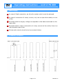
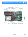
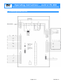
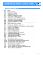
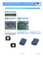
Operating instructions – Control FS 400 ENGLISH For fire-proof drives based on AS 130 ( fire alarms are specified as closer) Page 1 of 11 Revision 01 ENGLISH Operating instructions – control FS 400 Detailed view Legend K2 F2 K3 X0 K4 Duplication of limit switch CLOSED Control protection Triggering direct current motor Connecting terminals Time lag relay delay CLOSED Please find further details related to board plate AS 130 in enclosed detailed description „board plate AS 130“. Page 2 of 11 Revision 01 Operating instructions – Control FS 400 ENGLISH Description of function Legend The control FS 400 should trigger fire-proof drives which closes the fire doors automatically in case of fire. This function is controlled by a fire alarm contact and is active without primary power supply (loss of power). Of course, in operation mode at normal rating, the drive can also be operated by a conventional triple switch. The control is based on the MFZ control board plate AS 130 which overtakes the fundamental functions of gate control. In the basic version, it is conceived for dead-man operation mode. But it can be individually extended by plugging in plug-in modules. The gate is opened and closed by the motorised drive. Triggering of auxiliary motor is overtaken by relay K2 and K3. The motor receives its power supply (24V DC) through the integrated accumulator which is permanently loaded in operation mode at normal rating. In case of fire, the gate is closed by a permanent signal from the fire alarm. This occurs by means of the additionally installed direct current motor. In case of loss of power, the direct current motor continues to be supplied with power by the accumulator. This way, this function is also effective in case of fire. Safety instructions Consider the valid directives and regulations related to motorised gate units in your country. Installing and maintenance works on the control FS400 should only be done by personal specialised in electrics. Consider the protecting regulations! During works on electrics, the unit should be switched off power. Dead-man operation mode is only allowed if the unit is visible from the instruction devices. If you do not consider and respect the safety instructions, you will be the solely responsible of resulting personal injuries and property damages. Page 3 of 11 Revision 01 ENGLISH Operating instructions – control FS 400 Mains supply In case of fixed connection, an all pollo master switch must be planned. In case of connection of rotary current, only use a triple block safety cut-out (10A). Be aware that the supply voltage corresponds to the data mentioned on the type plate. Be aware that in case of connection of rotary current at the outlet, there is a right handed rotary field. Drives and controls should only be mounted indoor. Conductor connection Page 4 of 11 Revision 01 Operating instructions – Control FS 400 ENGLISH Grundplatine AS 130 Page 5 of 11 Revision 01 ENGLISH Operating instructions – control FS 400 Connecting scheme AS 130 Page 6 of 11 Revision 01 Operating instructions – Control FS 400 ENGLISH Legend board plate AS 130 Page 7 of 11 Revision 01 ENGLISH Operating instructions – control FS 400 X0 Page 8 of 11 Revision 01 Operating instructions – Control FS 400 ENGLISH Accessories related to board plate AS 130 ASO 11 Module for self-locking OPEN ASO 13 ASO 16 Module to connect SKS and AS radio Automatic reclosing Module to connect SKS and AS radio Automatic reclosing with red light time HF – Receiver Single channel handheld transmitter 2 channels hand-held transmitter for radio 433/868 MHz (Function OPEN/Stop/CLOSE) (Only with board plate ASO 13, 15, 16, 17) for radio 433 MHz for radio 868 MHz Page 9 of 11 Revision 01 Operating instructions – control FS 400 ENGLISH Battery charger Be aware! During operation of battery charger, dangers may arise from: - Danger of explosion ( by development of explosive gazes during charge of lead accumulators), - Fire hazard and danger of short-circuit ( by electric shock in combination with humidity). To exclude endangering situations: ● care for sufficient aeration. ● avoid fire and open light. ● only use the battery charger in dry places indoor. ● protect the device from humidity. Display ( type Friwo ): LED red: The device is in charging mode. LED green: The charging process is completed, the device is in conservation mode. Safety instructions The battery chargers should charge exclusively lead batteries free of maintenance. The charging device should only be opened by specialised personal and never be operated in open state. The guarantee expires in case of damaging the device by inappropriate opening. Before start up the device, make sure that the area is aerated enough. The device should only be operated in closed places and not exposed to humidity. Any change on the device lead to expiry of device licensing. Page 10 of 11 Revision 01 Operating instructions – Control FS 400 ENGLISH Instructions related to charging of lead batteries free of maintenance Before longer interval of use (two possibilities) Â Separate your battery from battery charger and store it fully charged. In case of interval of use longer than three months, charge the battery at least 36 hours. Â You can go on charging your battery with switched on battery charger (conservation charging). It is recommended to store the battery in a cool place. High temperatures It is not recommended to charge the battery in an ambient temperature of more than 30°C. Your battery charger is adjusted by fabrication with a charging tension that is based on an ambient temperature of 20°C. Low temperatures Charging the battery at an ambient temperature of less than 10°C is not recommended. By lower temperature, the extractable capacity is lower. Total discharge Please avoid total discharge. Nevertheless, if it comes to a total discharge, charge the battery soon after, longer than 24 hours. Page 11 of 11 Revision 01