1
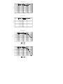
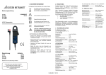
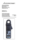
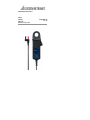
CP 30 35 GermanCp 41_CP C Operating Instructions CP 30 CP 330 CP 1100 AC/DC current probe 3-349-600-37 1/7.10 Order Reference CP 30 CP 330 CP 1100 Order No. Z201B Z202B Z203B Battery is included. Thank you for buying this product. For safety reasons and optimum use of this instrument read through the operating instructions very carefully. Table of Contents 1 SAFETY ................................................. 3 2 INTRODUCTION .................................... 4 3 SPECIFICATIONS.................................. 4 3.1 Electrical data................................. 4 3.2 General data .................................. 5 4 OPERATING INSTRUCTIONS............... 7 4.1 Switch On....................................... 7 4.2 Auto Zero ...................................... 7 4.3 Current Measurement .................... 7 4.4 Auto Power OFF ............................ 7 4.5 Battery Replacement...................... 7 5 SAFETY STANDARDS .......................... 8 6 WARRANTY........................................... 9 7 PRODUCT SUPPORT............................ 10 8 REPAIR AND REPLACEMENT PARTS SERVICE DKD CALIBRATION CENTRE AND RENTAL INSTRUMENT SERVICE 10 2 1. SAFETY The following symbols appear on the products: Do not dispose of this product as unsorted municipal waste. Contact a qualified recycler for disposal. Attention! Refer to Manual Double/Reinforced Insulation Application around and removal from HAZARDOUS LIVE conductors is permissible Complies the relevant European Complieswithwith the relevant European standards. standards Read the operating instructions completely and carefully before placing your instrument into service, and follow all instructions contained therein. To avoid electric shock: • Use caution during installation and use of this product; high voltages and currents may be present in circuit under test. • This product must be used only by qualified personnel practising applicable safety precautions. • Do not use product if damaged. • Always ensure the probe is removed from any live electrical circuit, before removing the battery cover. • Do not hold the probe anywhere beyond the tactile barrier see FIG 1, in order to avoid dangerous contact with the conductor. 3 2. INTRODUCTION The CP 30, CP 330 and CP 1100 AC/DC current probe have been designed for reliable and accurate, nonintrusive measurement of AC, DC and complex waveform currents. Using advanced Hall Effect technology the CP 30, CP 330 and CP 1100 can measure currents accurately up to 30 Amps (CP 30), up to 450A (CP 330) and up to 1400A (CP 1100). Measurement features include: AC and DC current measurement High accuracy 1mA / 50mA / 100 mA Resolution Auto Power Off These features make it a powerful tool for use in inverters, switch mode power supplies, industrial controllers and other applications requiring current measurement and/or waveform analysis. 3. SPECIFICATION 3.1 Electrical data (All accuracies stated at 23°C ± 1°C) CP 30 (Z201B) Measuring range........................ 0 to 30A DC or ACpk Current Range ........................... 30A Resoution .................................. 1mA Overload capacity (60s)............. 500A Overall DC accuracy.................. ±1% of rdg ±2mA Temperature Coefficient ............ ±0.01% of reading/°C Frequency range ....................... DC to 20kHz (-1dB) CP 330 (Z202B) Measuring range........................ 0 to 450A DC or ACpk Current Ranges ......................... 30A / 300A Resoution .................................. 10mA / 100mA Overload capacity (60s)............. 600A Overall DC accuracy.................. ±1% of rdg ±50/100mA Frequency range ....................... DC to 20kHz (-3dB) CP 1100 (Z203B) Measuring range........................ 0 to 1400A DC, ACpk Current Ranges ......................... 100A / 1000A Resoution .................................. 100mA / 500mA Overload capacity (60s)............. 2000A Overall DC accuracy.................. ±1% of rdg ±100/500mA Frequency range ....................... DC to 20kHz (-3dB) 4 3.2 General data Overall DC accuracy................. ±1% of rdg Working voltage ........................ Operating temperature.............. 300V ACRMS or DC 0°C to +50°C Storage temperature with battery removed ........................ -20°C to +85°C Power supply ............................ 9 V Alkaline battery PP3, MN 1604 or IEC6LR61 Battery life .............................. 30 hours (typical) Output connection:................. 1.5m cable with 4mm safety connectors Conductor size....................... ............................................... 25 mm diameter 32 mm (CP 1100) Weight.................................... 320 g Dimensions (mm)................ 194 (H) x 74 (W) x 25 (D) CP 1100........ 200 (H) x 74 (W) x 25 (D) 5 2 1 3 4 6 4 7 8 9 FIG 1 1. Jaws 2. Conventional current direction 3. Safety zone delimiter (Tactile Barrier): Do not reach beyond the safety collar! 4. Battery cover 5. Battery cover screw 6. Jaw trigger 7. ON/OFF / Range switch 8. Auto zero button 9. LED 6 5 4. OPERATING INSTRUCTIONS 4.1 Switch On When the probe is switched on, the green LED will illuminate. The LED starts flashing when the battery voltage is too low for normal operation and warns the user that it requires changing. This procedure is described in Section 5. 4.2 Auto Zero The output zero offset voltage of the probe may change due to thermal shifts and other environmental conditions. To null the output voltage depress the Auto Zero button. Ensure that the probe is away from the current carrying conductor whilst the probe is being nulled. 4.3 Current Measurement Switch on the probe and check that the LED is lit. Connect the output lead to an oscilloscope, multimeter or other measuring equipment. Zero the probe using the Auto Zero button. Clamp the jaws of the probe round the conductor ensuring a good contact between the closing faces of the jaws. Observe and take measurements as required. Positive output indicates that the current flow is in the direction shown by the arrow on the probe. 4.4 Auto Power OFF In order to save battery life, the probe will automatically switch itself off after approximately 10 minutes. To disable the Auto power off function, Switch Off the probe and Switch On whilst pressing the auto zero button. The red LED will illuminate and the probe will stay On until switched off again. 4.5 Battery Replacement SAFETY WARNING Before removing the battery cover, make sure that the probe is remote from any live electrical circuit. The green or red LED will flash when the minimum operating voltage is approached. Refer to Fig.1. Use the following procedure. 7 Unclamp the probe from the conductor, turn it off using the On - Off switch and disconnect the output leads, from external equipment. Loosen the captive screw which secures the battery cover. Lift the cover through 30° and pull it clear of the probe body as shown in Fig 1. Replace the battery and re-fit the battery cover and fasten the screw . Fit only Type 9 V PP3 Alkaline (MN 1604). 5. SAFETY STANDARDS EN 61010-1:2001 EN 61010-2-032:2002 EN 61010-031:2002 300V Cat III Pollution Degree 2 EMC Standards EN 61326-2-2:2006 ROHS and WEEE compliant This product is designed to be safe under the following conditions: - indoor use altitude up to 2000m temperature 0°C to +50°C maximum relative humidity 80% for temperatures up to 31°C decreasing linearly to 40% relative humidity at 50°C. Use of the probe on uninsulated conductors is limited to 300V ACRMS or d.c. and frequencies below 1kHz. Safety in its use is the responsibility of the operator who must be a suitably qualified or authorised person. Ensure that your fingers are behind the protective barrier see FIG 1 when using the probe. Always inspect the probe for damage before use. To avoid electric shock, keep the probe clean and free of surface contamination. Use Isopropyl alcohol to clean the probe. 8 6. WARRANTY Your AC/DC current probe is guaranteed for two years from the date of purchase against defective material or workmanship. If the unit fails during the warranty period, we shall at our discretion, repair or replace it with a new or reconditioned unit provided we are satisfied that the failure is due to defective material or workmanship. To make a claim under warranty, the probe should be returned to us, postage prepaid, with a description of the defect. The use of a battery or external power supply, other than that specified invalidates this warranty. Goods alleged by the buyer to be defective shall not form the subject of any claim for injury, loss, damage, or any expense howsoever incurred whether arising directly or indirectly from such alleged defects other than death or personal injury resulting from the seller‘s negligence. No condition is made or to be implied nor is any warranty given or to be implied as to the life or wear of goods supplied or that they will be suitable for any particular purpose or for use under specific conditions, notwithstanding that such purpose or conditions may be made known to the seller. 9 7 PRODUCT SUPPORT If required please contact: GMC-I Messtechnik GmbH Product Support Hotline Phone: +49 911 86 02-0 Fax: +49 911 86 02-7 09 Email: [email protected] 8 REPAIR AND REPLACEMENT PARTS SERVICE DKD CALIBRATION CENTRE AND RENTAL INSTRUMENT SERVICE If required please contact: GMC-I Service GmbH Service Center Thomas-Mann-Strasse 20 90471 Nürnberg, Germany Phone: Fax: E-mail: +49 911 817718-0 +49 911 817718-253 [email protected] This address is only valid in Germany. Please contact our representatives or subsidiaries for service in other countries. CP30_CP330_CP1100 English Rev 1.0 10 CP30 Frequency Response 0.500 0.000 Attenuation (dB) -0.500 -1.000 -1.500 -2.000 -2.500 -3.000 10 100 1000 10000 100000 10000 100000 10000 100000 10000 100000 Frequency (Hz) CP30 Frequency Response 5.00 0.00 -5.00 Phase Shift (°) -10.00 -15.00 -20.00 -25.00 -30.00 -35.00 -40.00 -45.00 10 100 1000 Frequency (Hz) CP330 Frequency Response 0.500 0.000 Attenuation (dB) -0.500 -1.000 -1.500 -2.000 -2.500 -3.000 10 100 1000 Frequency (Hz) 30A Range 300A Range CP330 Frequency Response 5.00 0.00 -5.00 Phase Shift (°) -10.00 -15.00 -20.00 -25.00 -30.00 -35.00 -40.00 -45.00 10 100 1000 Frequency (Hz) 30A Range 11 300A Range CP1100 Frequency Response 0.500 0.000 Attenuation (dB) -0.500 -1.000 -1.500 -2.000 -2.500 -3.000 10 100 1000 10000 100000 10000 100000 Frequency (Hz) 100A Range 1000A Range CP1100 Frequency Response 5.00 0.00 -5.00 Phase Shift (°) -10.00 -15.00 -20.00 -25.00 -30.00 -35.00 -40.00 -45.00 10 100 1000 Frequency (Hz) 100A Range 12 1000A Range