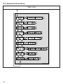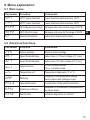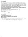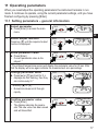
1
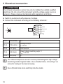
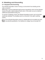
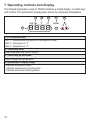
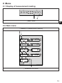
Operating instructions
Infrared temperature sensor
UK
706365 / 00 03 / 2014
TW20xx
°F °C
Contents
1 General����������������������������������������������������������������������������������������������������������������4
1.1 Information about this manual�����������������������������������������������������������������������4
1.2 Liability and Warranty������������������������������������������������������������������������������������4
1.3 Copyright�������������������������������������������������������������������������������������������������������5
2 Safety������������������������������������������������������������������������������������������������������������������5
2.1 Intended use��������������������������������������������������������������������������������������������������5
2.2 User’s responsiblity���������������������������������������������������������������������������������������5
2.3 Safety requirements��������������������������������������������������������������������������������������5
2.4 Electromagnetic Compatibility�����������������������������������������������������������������������5
3 General Description���������������������������������������������������������������������������������������������6
4 Function���������������������������������������������������������������������������������������������������������������6
4.1 Switching threshold���������������������������������������������������������������������������������������7
4.2 Output signal ������������������������������������������������������������������������������������������������7
4.3 Upper threshold delay�����������������������������������������������������������������������������������7
4.4 Lower threshold delay�����������������������������������������������������������������������������������7
4.5 Switching functions����������������������������������������������������������������������������������������8
4.6 Internal signal processing �����������������������������������������������������������������������������9
4.7 Analogue output���������������������������������������������������������������������������������������������9
5 Electrical connection �����������������������������������������������������������������������������������������10
6 Shielding and Grounding����������������������������������������������������������������������������������� 11
6.1 Equipotential bonding���������������������������������������������������������������������������������� 11
7 Operating controls and display��������������������������������������������������������������������������12
8 Menu������������������������������������������������������������������������������������������������������������������13
8.1 Display of measurement reading ����������������������������������������������������������������13
8.2 Main menu ��������������������������������������������������������������������������������������������������13
8.3 Advanced functions�������������������������������������������������������������������������������������14
9 Menu explanation����������������������������������������������������������������������������������������������15
9.1 Main menu���������������������������������������������������������������������������������������������������15
9.2 Advanced functions�������������������������������������������������������������������������������������15
10 Setup���������������������������������������������������������������������������������������������������������������16
11 Operating parameters��������������������������������������������������������������������������������������17
2
11.1 Setting parameters – general information��������������������������������������������������17
11.2 Change between the menu layers ������������������������������������������������������������18
11.3 Test function�����������������������������������������������������������������������������������������������18
11.4 Damping function���������������������������������������������������������������������������������������19
11.5 Peak hold function�������������������������������������������������������������������������������������19
11.6 Reset all parameters to factory settings�����������������������������������������������������20
12 Operation���������������������������������������������������������������������������������������������������������21
12.1 Display of the configuration parameters in the main menu�����������������������21
12.2 Display of the configuration parameters for advanced functions���������������21
12.3 Ambient temperature���������������������������������������������������������������������������������21 UK
12.4 Error indications�����������������������������������������������������������������������������������������21
13 Ways to determine emissivity��������������������������������������������������������������������������22
13.1 Emissivity coefficient tables�����������������������������������������������������������������������23
14 Maintenance����������������������������������������������������������������������������������������������������25
14.1 Cleaning the pyrometer lens����������������������������������������������������������������������25
15 Shipping, packaging and disposal�������������������������������������������������������������������25
15.1 Transport-Inspektion����������������������������������������������������������������������������������25
15.2 Packaging��������������������������������������������������������������������������������������������������26
16 Copyright���������������������������������������������������������������������������������������������������������26
17 Default settings (factory settings)��������������������������������������������������������������������27
3
1 General
1.1 Information about this manual
The Operating Manual shall enable the user to properly install the infrared temperature sensor and the required accessories.
Before starting installation, be sure to read and understand this entire manual,
in particular the chapter on safety! The instructions contained in this manual,
especially those concerning safety, as well as site specific regulations governing
UV radiation must be complied with at all times. It is imperative to comply with
the safety instructions and the accident protection regulations valid for the area of
application.
Explanation of symbols
Important safety-related references in this manual are marked with a symbol.
ATTENTION
This symbol points out guidelines. If you do not observe them, the device might
be damaged, malfunctioning or even fail to operate.
CAUTION
This symbol points out hints and information which should be heeded for
efficient and trouble-free operation
► Action
This symbol instructs the operator to take action.
> Reaction, Result
This symbol indicates the result of the action taken.
1.2 Liability and Warranty
All information compiled in this manual is in accordance with applicable regulations. The statements made are based on state-of-the-art technology and reflect
our ex-tensive knowledge and many years of experience.
Always carefully read this Operating Manual before beginning any work on
or with the in-strument, especially prior to installation and initial setup! The
Manufacturer shall not be held liable for any damages or malfunctions arising from a disregard of the warnings and instructions contained herein..
4
1.3 Copyright
This Operating Manual should be treated as confidential. It is solely intended
for use by persons involved with the instrument. This manual may not be made
available to a third party without prior Manufacturer’s consent. Please contact the
Manufacturer if the need should arise.
2 Safety
This chapter outlines all important safety aspects to be considered for optimum
employee protection and to ensure safe and reliable operations.
UK
2.1 Intended use
The infrared temperature sensor is solely intended for use as described in this
manual. Operational safety can only be ensured when the instrument is used for
its in-tended purpose.
Jede The use of the infrared temperature sensor for any other purpose
beyond what is specified in this manual is prohibited. Using the instrument
in any other manner will be considered as improper.
The Manufacturer/Authorised Agent shall not be held liable for any damages or loss resulting from such unintended or improper use; in this case
the risk is solely borne by the user.
2.2 User’s responsiblity
The infrared temperature sensor may only be used when it is in perfect working
condition.
2.3 Safety requirements
The instrument operates at low voltage (10 – 34 V DC). The power supply unit
must conform to directive EN50178, SELV, PELV
2.4 Electromagnetic Compatibility
The instrument complies with the requirements of EC
Directive 89/336/EEC changed by 91/263/EEC; 92/31/EEC; 93/68/EEC relating to
radio interference suppression and electromagnetic compatibility.
5
European certification:
EN 61000-6-4
EN 61000-6-2
EN 61000-4-2/-3/-4/-6
EN 55011
When connecting a power supply unit, make sure that is also conforms to these
standards. Radio interference may arise if the infrared temperature sensor is
intercon-nected with such peripheral devices which have not been properly
interference-suppressed. This may necessitate additional interference suppression
measures.
3 General Description
The infrared temperature sensor detects temperatures and monitors temperature
ranges without contact.
The sensor detects the infrared energy radiated by a hot object and converts this
to an electric switch signal.
The advantage of this technique is that there is no me-chanical contact between
the sensor and the hot object.
The instrument is suitable for the following applications:
• Measurements at moving or hard-to-reach objects
• Measurements at surface-treated or voltage-carrying objects
• Measurements at sticky materials such as dough or aggressive chemicals
• Applications requiring fast response times.
The rugged stainless steel housing enables the instrument to be used in harsh
industrial environments. The instruments are splash-proof according to IP65 (DIN
40050). The infrared temperature sensor has an analogue output and a switching
contact which can be used as normally closed or normally open contact, depending on the configuration.
4 Function
The infrared temperature sensor measures the temperature without contact to the
target.
The infrared sensor is equipped with an analogue output and an open collector
output. The instrument's display panel shows the measured temperature..
6
• It generates 2 output signals according to the configured function:
OUT1
Switching threshold
OUT2
Analogue output 4...20 mA
4.1 Switching threshold
OUT1 changes its switching status when the configured upper and lower thresholds (SP1, rP1) are exceeded.
First set the switch point [SP1] in °C or °F. Then set the lower threshold [rP1].
UK
When you adjust the upper threshold [SP1] the lower threshold [rP1] will change
accordingly. The span remains the same. If [SP1] is lowered to a value where the
span cannot be maintained (as [rP1] would then fall below its minimum value), the
[rP1] is kept with its minimum value. If [SP1] subsequently increases again, [rP1]
also immediately increases.
4.2 Output signal
The following switching functions can be selected:
• Normally open contact: [EF] → [ou1]= Hno (normally open)
• Normally closed contact: [EF] → [ou1]= Hnc (normally closed)
4.3 Upper threshold delay
Once the sensor has detected a temperature which exceeds the switching
threshold [SP1] the time delay [dS1] starts running. When this delay period has
elapsed, the output OUT1 activates switching. This status is sustained until the
lower threshold [rP1] is violated. If this occurs before the time delay has elapsed,
the delay will reset. This function can be used, for example, to suppress spurious
impulse signals at the output.
• Upper threshold delay: [EF] → [dS1] = x s
4.4 Lower threshold delay
To make sure the output impulse is correctly identified, e.g. by a downstream
control system, the output impulse can be lengthened.
• Lower threshold delay: [EF] → [dr1] = x s
7
4.5 Switching functions
1:
2:
3:
4:
5:
8
Teperature profile
Switch signal Hno
Switch signal Hno with upper- and lower threshold delay
Switch signal Hnc
Switch signal Hnc with upper- and lower threshold delay
4.6 Internal signal processing
Temperature
↓
Switch point
→
no / nc
→
Lower- / upper threshold
delay
↓
Switching
4.7 Analogue output
UK
The infrared temperature sensor is equipped with an analogue output OUT2
4...20 mA. The maximum load is 500 Ω. The output current is linear to the
measured temperature. The output current is linear to the measured temperature.
Within the overall measuring range, the required measuring range can be set to
°C or °F using parameter [ASP2] (scale beginning) and parameter [AEP2] (scale
end).
Emissivity of materials:
The infrared temperature sensor reacts to the thermal energy (infrared
radiation) emitted by an object. The ability to radiate heat depends on the
type of material and its surface properties. A description of the calculation
of emissivity is in Chapter 13/ Page 23. The ability of a body to emit infrared
radiation is expressed by a material constant called emissivity coefficient or
just emissivity. This coefficient lies between 0 and 100 %. A body with ideal
radiation (black body) has a coefficient of 100 %. At the same temperature,
bodies with real radiation emit a lower radiation. Therefore, the emissivity coefficient is < 100%. Um mit dem Infrarot-For this reason, adjust the
emissivity coefficient of the target object on the infrared temperature sensor
to be able to determine the exact temperature. With the configured lower
emissivity coefficient, the infrared temperature sensor automatically compensates for the lower radiation.
• Emissivity: [EF] → [EPS1] = x s
9
5 Electrical connection
ATTENTION
The infrared temperature sensor may only be installed by a skilled, qualified
electrician. Do not connect the instrument while the voltage supply source is
turned on. Please observe international safety regulations at all times.
►► Switch to neutral and verify absence of voltage
►► Connect the instrument according to the following schematic:
2
1
5
3
4
Pin 1
BN (brown)
L+
Pin 2
WH (white)
Analogue output
4...20 mA
Pin 5
GY (grey)
Test Input pin
Pin 4
BK (black)
Open Collector switching output 1
Imax = 150 mA
Pin 3
BU (blue)
L-
The infrared temperature sensor must be protected against high voltage
and strong electromagnetic fields. Use a shielded cable, connecting it via
connector casing to the device housing.
Use a flyback diode when switching inductive loads.
10
6 Shielding and Grounding
6.1 Equipotential bonding
The infrared temperature sensor housing is connected to the shielding via the
cable connector!
Differences in ground potentials might cause an equalising current to flow between
devices through a cable shielded at both ends. In this case, be sure to install an
additional equipotential bonding line.
To avoid an equalising current, the infrared temperature sensor can be mounted
electrically insulated. The shielding must be connected to the plant’s earthing
UK
system.
If the infrared temperature sensor is installed without an insulator and without potential equalisation, the interference voltage may not exceed 32V.
11
7 Operating controls and display
The infrared temperature sensorr TW20xx features a 4-digit display, 3 control keys
and 3 LEDs. The instrument's display panel shows the measured temperature
1 to 3: Indicator-LEDs
LED 1 = indicates switching output of the respective output
LED 2 = temperature in °F
LED 3 = temperature in °C
4: Control key Enter
Select parameter and confirm setting
5: Control key up and down
Adjust configuration parameters
6: Alphanumeric display, 4-digit
•Indicates temperature value
•Indicates parameters and configuration
•Indicates overload at switching output
12
8 Menu
8.1 Display of measurement reading
↓ Main menu
UK
8.2 Main menu
↑ Display of measurement reading
↓ Advanced functions
13
8.3 Advanced functions
↑ Main menu
14
9 Menu explanation
9.1 Main menu
Parameter
Function
Comments
SP1
OUT1 Upper threshold
Upper threshold which activates OUT1
rP1
OUT1 Lower threshold
Lower threshold which activates OUT1
ASP2
OUT2 Beginning of range
Analogue start value for the range of OUT2
AEP2
OUT 2 End of range
Analogue end value for the range of OUT2
EF
Advanced functions
select menu advanced functions
UK
9.2 Advanced functions
Parameter
Function
Comments
rEs
Factory settings
Reset to factory settings
dS1
Upper threshold delay
Value in sec (≤ 10 sec in steps of 0.1 sec)
dr1
Lower threshold delay
Value in sec (≤ 10 sec in steps of 0,1 sec)
ou1
Output function
Hno normally opened
Hnc normally closed
uni
Temperature unit
Temperature displayed in °F or °C
dAp
Damping
Damping for the temperature display,
switch outputs and analogue output
PhLd
Peak hold function
Configuration of the peak hold function
EPSI
Emissivity coefficient
Adaptation of the radiation characteristics of
the target object.
tEst
Test function
Activates diagnostics for self-test
15
10 Setup
The infrared temperature sensor uses the intensity of infrared radiation for noncontact temperature measurements. It is necessary to configure the infrared temperature sensor to the respective emissivity coefficient of the measuring object to
obtain exact measuring results (→ 13 Emissivity coefficient tables). An incorrectly
set emissivity coefficient leads to wrong temperature readings.
Set the emissivity coefficient after connecting the supply voltage or resetting the
parameters to factory settings.
The display then shows three horizontal strokes [%%%%].
The emissivity is set as follows:
►► Press [Enter]
>> The display shows [EPS1]
►► Press [Enter]
>> the display shows [nonE]
►► [▼] hold key until the required value is displayed
►► Press [Enter]
>> The current temperature value is displayed. The infrared temperature sensor
now works with this configured emissivity until it is changed again.
16
11 Operating parameters
When you reset/adjust the operating parameters the instrument remains in run
mode. It continues to operate, using the current parameter settings, until you have
finished configuring by pressing [Enter].
11.1 Setting parameters – general information
1
Select parameter
►► Press [Enter] to access the main
menu.
UK
2
Select output function
Press key [▼] until the required output
function is displayed.
3
Show parameter value
►► Press [Enter]
>> Current parameter value is displayed. *
* The infrared temperature sensor will display the parameter value for 30 sec. After
that the display will once again indicate the measurement as a percentage
4
Change parameter value
►► Press [▲] or [▼] and hold for 3 s
>> displays are first flashing, then they
are continuously lit.*
* Hold key [▲] or [▼] .
>> Numerical values scroll through
rapidly
5
Confirm parameter value
►► Press [Enter]
>> The display indicates the parameter.The new value has been saved
and will take effect.
17
Adjust additional parameters
►► Start again with step 2.
Exit operating parameters layer
►► Wait 30 s
or
►► Switch over [▲] or [▼] from the advanced functions menu to the main menu, from the
main menu to the measurement reading.
The instrument features a keylock. Activate/deactivate the keylock as follows:
►► Press key [▲▼] simultaneously and hold them down for 10 sec.
>> The display shows loc or unlock for 1 sec .
If you press both keys [▲▼] only briefly, you will exit the layer (ESC function).
11.2 Change between the menu layers
Change to the submenu advanced
functions
Use parameter [EF].
►► Select submenu with [▼] and
press [Enter] to change to the
submenun
Back to measurement reading
►► Wait 30 sec
or
►► return with [▲] or [▼] vfrom the
submenu to the main menu, from
the main menu to the measurement reading
11.3 Test function
The infrared temperature sensor features an integrated diagnostics function to
check signal processing, the switching output and the analogue output. It can be
activated either using the control keys or by a static signal (10...34 V according to
IEC 61131-2) on Pin 5. Voltage must be applied for at least t > 300 ms. The unit
performs a self test. The display shows OL(analogue output 20.5 mA).
To deactivate the diagnostics function, the static signal must be available for a
period of 300 msec "Low".
18
If the diagnostics function is activated using the control keys on the instrument, it
will remain in this mode for 10 sec.
If the diagnostics function is not used, connect the diagnostics input (Pin
5) to minus. As an alternative, use a 4-pole cable box where Pin 5 is not
assigned.
11.4 Damping function
When the target object's temperature is erratic, the damping function smoothens
these temperature fluctuations in order to stabilize the measuring signal. The
greater the time constant [DAP], the lower the effect of these fluctuations on the UK
yielded temperature reading.
OUT2
[mA]
1
2
t
1: Output signal without smoothing function
2: Output signal with smoothing function
11.5 Peak hold function
It might often be desirable to determine the peak temperature during a defined
time period, for example when the objects to be measured move past the infrared
temperature sensor, resulting in temperature readings which would appear to be
cyclical. In this mode, the displayed temperature reading will not drop between targeted objects. The peak temperature reading will be held for a preset time period.
The hold time [PhLd] can be set at 100, 300 and 500 msec. The maximum
temperature sampled during the defined hold time will be saved. It makes sense to
choose a hold time which is approximately 1.5 times as long as the cycle of the moving targets. This avoids temperature drops. Any changes are recognised at once.
19
1
OUT2
[mA]
2
3
4
5
t
1:
2:
3:
4:
5:
Measuring object in front of infrared temperature sensor
Hold time
second internal hold time
Measuring readings with peak hold function
Measuring readings without peak hold function
11.6 Reset all parameters to factory settings
►► [rES] select in menu advanced functions
►► Press [Enter]
►► [▲] or [▼] and hold
>> [----] is displayed
►► Press [Enter]
>> The display shows %%%%
After a reset to factory settings configure the emissivity coefficient
[EPSI] again (→ ) to obtain exact measuring results.
20
12 Operation
After connecting the supply voltage the infrared temperature sensor will be
automatically initialized and will perform a self-diagnosis. After approx. 0.5 sec the
sensor is ready to operate and the instrument runs the signal processing.
12.1 Display of the configuration parameters in the main menu
►► Press [Enter] to access the main menu
►► [▼] press key until the required parameter is displayed.
►► Press [Enter]
UK
>> The display will indicate the parameter value for 30 sec. After that it returns to
Run Mode.
12.2 Display of the configuration parameters for advanced
functions
►► Press [Enter]
►► [▼]. Press key until the parameter [Ef] is displayed.
►► Press [Enter]
►► [▼]. Press key until the required parameter is displayed.
►► Press [Enter]
>> The display will indicate the parameter value for 30 sec. After that it returns to
Run Mode.
12.3 Ambient temperature
The maximum permissible ambient operating temperature for the infrared temperature sensor is 65 °C. If the instrument is used in ambient temperatures above
65 °C, it must be either cooled or shielded from excess radiant heat by means of a
deflector plate.
12.4 Error indications
Overload output
The corresponding LED will flash at 4 Hz. The
display shows "SC1" at 2 Hz.
21
Overtemperature
Display ot alternately shows overtemperature and measurement reading at = 0.5 Hz.
The corresponding LED flashes at 4 Hz when
the output is switched off.
Incorrect connection of supply voltage
Switching output LED flashes at 2 Hz.
Supply voltage
≤ approx. 16 V
LED, display, switching output and analogue
output are deactivated.(When voltage ≥ 16
V the device switches on and the switching
outputs are activated).
Temperature below lower
threshold
The display shows UL.
Temperature above upper
threshold
The display shows 0L.
13 Ways to determine emissivity
Technical literature or operating manuals often contain data on the emissivity of
various materials. This information should be used with caution, however. It is
important to know for which temperature and which wavelength the emissivity
value is applicable. Furthermore, the stated emissivity values were obtained under
ideal conditions. In actual practice, the total emissivity of the target object will vary,
depending on the amount of extraneous radiation transmitted through the object
from the background or reflected onto the object from the foreground.
The emissivity can be determined using one of the following methods:
Contact measurements
Measure the temperature with a contact thermocouple and measure the surface
temperature with a pyrometer. Adjust the emissivity coefficient on the pyrometer
until both devices show the same temperature. When measuring with the thermocouple, make sure to have good thermal contact and low heat dissipation.
22
Using a reference emissivity coefficient
Apply matte black colour to a part of the surface to be measured. This part has an
emissivity of 94 %. At first, measure the temperature of the coloured part. Then
make a comparative measurement right next to the coloured part and adjust the
emissivity on the pyrometer until it displays the previous measurement reading
again.
13.1 Emissivity coefficient tables
List of emissivity coefficients of different materials in %.
Model
Wavelength λ
"Black body"
Aluminium oxide
Asphalt
Baking oven, dark colour
Concrete
Bitumen (roofing paper)
Bread in baking oven
Ferrous oxide
Enamel
Earth
Paint and varnish, bright
Paint and varnish, pale
Gypsum
Glass
Graphite
Rubber, black
Skin, human
Wood
Radiator
Lime cast
Clinker bricks, glazed
Cooking plate
Synthetic material, nontransparent
UK
TW2000
8...14 μm
100
76
90...98
96
55...65
96
88
85...89
84...88
92...96
92
94
80...90
85...95
98
94
98
80...90
80...85
91
75
95
65...95
23
Model
Copper, oxidized
Leather
Marble
Brass, oxidized
Paper
Sand
Fireclay
Steel, stainless
Steel, rusty
Textiles
Water
Cement
Bricks
TW2000
78
75...80
94
56...64
70...94
90
75
45
69
75...88
92...98
90
93...96
Model
Wavelength λ
"Black body"
Aluminium, polished
Aluminium, filed smooth
Asbestos cement
Bronze, polished
Bronze, filed smooth
Chromium, polished
Iron, heavily scaled
Iron, rolling skin
Iron, liquid
Gold and silver
Graphite, filed smooth
Copper, oxidised
Brass, oxidised
Nickel
Porcelain, glazed
TW2001 / TW2011
1,1...1,7 μm
100
5
10
60
1
15
15
90
75
15
1
85
70
50
8
50
24
TW2002
0,78...1,06 μm
100
15
25
70
3
30
30
95
90
30
2
90
90
70
20
60
Model
Porcelain, rough
Soot
Fireclay
Slag
Pottery, glazed
Bricks
Zinc
TW2001 / TW2011
75
90
40
80
85
85
40
TW2002
85
95
50
85
90
90
60
UK
14 Maintenance
14.1 Cleaning the pyrometer lens
A false temperature reading will be given when the lens is dirty.
Therefore, check the lens periodically and clean it, if necessary.
Dust can be removed by simply blowing it away or by using a soft brush.
A special lens cleaning cloth is ideal, but any soft, clean, lint-free cloth will be
suitable.
If the lens is quite dirty, use a very mild liquid detergent and rinse carefully with
clear water while holding the device pointed down. Apply as little pressure as possible to avoid scratching the lens.
15 Shipping, packaging and disposal
15.1 Transport-Inspektion
Unpack and inspect the entire shipment immediately upon receipt to make sure it
is complete and undamaged. If the container/package shows visible signs of damage, please refuse the shipment. If this is not possible, accept the shipment on
the condition that the freight carrier’s delivery record is noted with the extent of the
damage in order to file a claim.Should you discover a concealed loss or damage,
report it to the shipper or freight carrier immediately. If the period for filing claims
has expired, you will no longer be able to make any claims for compensation of
damage or loss.
25
15.2 Packaging
The packages used are made of carefully selected, environmentally compatible
materials and are thus recyclable. Please ensure that they are disposed of in an
ecologically sound manner.
16 Copyright
The device software contains portions of the avr-libc library.
Portions of avr-libc are Copyright (c) 1999-2007
Keith Gudger,
Theodore A. Roth,
Bjoern Haase,
Juergen Schilling,
Steinar Haugen,
Philip Soeberg,
Peter Jansen,
Anatoly Sokolov,
Reinhard Jessich,
Nils Kristian Strom,
Magnus Johansson,
Michael Stumpf,
Artur Lipowski,
Stefan Swanepoel,
Marek Michalkiewicz,
Eric B. Weddington,
Colin O'Flynn,
Joerg Wunsch,
Bob Paddock,
Dmitry Xmelkov,
Reiner Patommel,
The Regents of the University of California.
Michael Rickman,
All rights reserved.
Redistribution and use in source and binary forms, with or without modification, are permitted
provided that the following conditions are met:
* Redistributions of source code must retain the above copyright notice, this list of conditions
and the following disclaimer.
* Redistributions in binary form must reproduce the above copyright notice, this list of conditions and the following disclaimer in the documentation and/or other materials provided with
the distribution.
* Neither the name of the copyright holders nor the names of contributors may be used to
endorse or promote products derived from this software without specific prior written permission.
THIS SOFTWARE IS PROVIDED BY THE COPYRIGHT HOLDERS AND CONTRIBUTORS "AS IS" AND
ANY EXPRESS OR IMPLIED WARRANTIES, INCLUDING, BUT NOT LIMITED TO, THE IMPLIED WARRANTIES OF MERCHANTABILITY AND FITNESS FOR A PARTICULAR PURPOSE ARE DISCLAIMED.
IN NO EVENT SHALL THE COPYRIGHT OWNER OR CONTRIBUTORS BE LIABLE FOR ANY DIRECT,
INDIRECT, INCIDENTAL, SPECIAL, EXEMPLARY, OR CONSEQUENTIAL DAMAGES (INCLUDING,
BUT NOT LIMITED TO, PROCUREMENT OF SUBSTITUTE GOODS OR SERVICES; LOSS OF USE,
26
DATA, OR PROFITS; OR BUSINESS INTERRUPTION) HOWEVER CAUSED AND ON ANY THEORY
OF LIABILITY, WHETHER IN CONTRACT, STRICT LIABILITY, OR TORT (INCLUDING NEGLIGENCE
OR OTHERWISE) ARISING IN ANY WAY OUT OF THE USE OF THIS SOFTWARE, EVEN IF ADVISED
OF THE POSSIBILITY OF SUCH DAMAGE.
17 Default settings (factory settings)
Parameter
Default parameters
TW2000 TW2001 TW2002 TW2011
OUT1
OUT2
EF
SP1
rP1
ASP2
ASE2
rES
dS1
dr1
ou1
uni
dAP
PhLd
EPSI
tESt
250 °C
230 °C
0 °C
1000 °C
500 °C
480 °C
250 °C
1600 °C
1000 °C
960 °C
500 °C
2500 °C
UK
User configuration
550 °C
530 °C
300 °C
1600 °C
0.0 s
0.0 s
Hno
°C
0.0 s
0
None
OFF
Weitere Informationen unter www.ifm.com
27