1
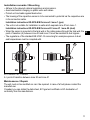
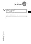
Operating instructions
(Safety-related part ATEX)
Capacitive NAMUR sensors
706139 / 00
01 / 2012
KX-2015-N/NI*
UK
Remarks for safe use in hazardous areas
Functions and features
• Use in hazardous areas according to the classification
II 1G (group II, category 1G, apparatus for gas atmosphere)
The standards IEC 60079-0: 2011, IEC 60079-11: 2011, IEC 60079-26: 2006+ Corr. 2009
are applied
• Use in hazardous areas according to the classification
II 1D (group II, category 1D, apparatus for dust atmosphere).
The standards IEC 60079-0:2011, IEC 60079-11:2011 are applied.
• EC Type Test Certificate
DMT 01 ATEX E020
• Marking
II 1G Ex ia IIB T6 Ga Ta: - 20°C to 60°C
II 1D Ex ia IIIC T90°C Da
Installation / Set-up
The units must only be installed, connected and set up by qualified staff. The qualified staff
must have knowledge of protection classes, regulations and provisions for apparatus in
hazardous areas.
Check whether the classification (see "Marking" above and marking on the unit) is suitable
for the application.
• Connection only to intrinsically safe switching amplifiers which are approved with the EC
type test certificate and do not exceed the following maximum values:
Ui = 15 V, Ii = 50 mA, Pi = 120 mW
• Permissible operating temperature of the application (referred to the maximum power
which can be supplied):
-20 ... +60°C
• Maximum effective internal inductance (Li) and capacitance (Ci):
Li = 1 μH, Ci = 375 nF
The values apply to potted cables which are 2 m long.
The following values are added for the cable unit versions KX**** with potted cable > 2m:
0.5 μH (Li) / 160 pF (Ci) per metre of potted cable.
2
Installation remarks / Mounting
• Adhere to the relevant national regulations and provisions.
• Avoid electrostatic charging on plastic units and cables.
• Protect unit and cable against destruction.
• The housing of the capacitive sensor is to be connected to potential via the respective wire
in the connection cable.
Installation instructions KX-2015-N/NI for zone 0 / zone 1 (gas)
• The unit is not suitable for installation in walls which separate zone 0 from zone 1.
Installation instructions KX-2015-N/NI for zone 20 / zone 21 / zone 22 (dust)
• When the sensor is mounted in the tank wall or the cable passes through the tank wall, the
UK
point of transition (A) between zone 20 and zone 21 must be resistant to dust ingress.
• The regulations of the standard EN 61241-14 concerning for example exposure to dust
and temperatures must be complied with.
A
20
21
A
20
21
20 = zone 20 / 21 = zone 21
A = point of transition between zone 20 and zone 21
Maintenance / Repair
The unit must not be modified nor can it be repaired. In case of a fault please contact the
manufacturer.
If needed, you can obtain the data sheet, EC type test certificate or EC declaration of
conformity from the manufacturer.
3