1
706027/00
04/2011
Operating instructions
Flow sensors
SF*1*A
UK
Operating instructions (safety-related part ATEX)
Remarks for safe use in hazardous areas
Functions and features
In conjunction with the control monitor VS2000 Exi the flow sensor monitors flows in liquid
and gaseous media and detects whether a preset flow value is reached (= medium is
flowing) or not (= medium is not flowing) and provides a switching signal.
• Use in hazardous areas according to the classification
II 1/2G (group II, category 1/2 G, apparatus for gas atmosphere).
• The flow sensors are suitable for installation in the partition 1/2G.
• The requirements of the standards EN 60079-0, EN 60079-11, EN 60079-26 are met.
EC type test certificate
DMT 03 ATEX E090 X
• Marking
II 1/2G Ex ia IIC T4 Ga/Gb Ta = -20 ... +60°C
Installation / Set-up
The units must only be installed, connected and set up by qualified staff. The qualified staff
must have knowledge of protection classes, regulations and provisions for apparatus in
hazardous areas.
Check whether the classification (see "Marking" above and marking on the unit) is suitable
for the application.
The flow sensors are only allowed to be connected to the specified control monitors
type VS2000 Exi type of protection intrinsic safety II (1) G [Ex ia] IIC
with the EC type test certificate PTB 01 ATEX 2075. Take the connection values into
account.
Connection to the following control monitors is allowed:
SN2301, SN2302, SN2303, SN2304, SR2301
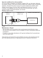
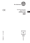
• Wiring
SF*1*A
2
BN
BK
GY
WH
BU
1
2
3
7
8
VS2000 Exi
• Process connections
SF11*A = M12
SF21*A = G¼
SF31*A = G½
• Permissible operating temperature range at the mounting location and maximum
temperature range of the medium:
-20 ... +60 °C
• In principle, the type test according to 94/9/EC only takes atmospheric conditions
(0.8...1.1bar and mixture temperatures of -20...+60°C) into account. For pressures outside UK
these ranges use must be assessed and approved by the user.
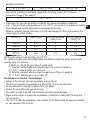
• Maximum effective internal inductance (Li) and capacitance (Ci) of the flow sensors (the
values apply to potted cables):
Article no.
Cable length
SF311A
SF211A
SF111A
SF*1*A
6m
6m
6m
xx m
Internal inductance
(total) in μH
6
6
6
1*)
Internal capacitance
(total) in nF
1.2
1.2
1.2
2*)
Articles with cable/variants of cable units SF*1*A:
For variants of cable units with potted cables of a different length the values of the cable
must be taken into account.
0.68 μH (Li) / 95 pF (Ci) per metre of potted cable.
*1) Thus the maximum effective internal inductance of the unit results in:
Li = 6 μH + cable length in (m) x 0.68 μH
*2) Thus the maximum effective internal capacitance of the unit results in:
Ci = 1.2 nF + cable length in (m) x 0.095 nF.
Installation remarks / Installation
• Adhere to the relevant national regulations and provisions.
• The relevant installation regulations (e.g. EN 60079-14) must be adhered to.
• Avoid electrostatic charging on plastic parts and cables.
• Protect the units efficiently against damage.
• The cable must be firmly laid and protected efficiently against damage.
• Steps must be taken to ensure the equalisation of potential of metal parts (housing and
fixing material).
• The unit is suitable for installation in the partition 1/2 G. Please take the special conditions
for safe operation into account.
3
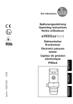
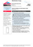
Special conditions for safe operation
The unit is suited for installation in the partition (category 1/2G); e.g. tank, pipes. Sealing at
the transition (category 1/2G) must be rated according to the conditions of the corresponding
application. The part of the sensor housing of corrosion-resistant steel (316S12) which
reaches into the category 1G (zone 0) has a wall thickness of minimum 0.6 mm due
to function. In the application the user must ensure that in this area risks, e.g. due to
aggressive media or mechanical hazards, are excluded.
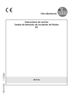
Mounting in pipes or tanks:
Category 1G
(zone 0)
Category 2G, 3G
(zone 1 or 2)
Outside the hazardous area
VS2000 Exi
1
1: seal
Maintenance / Repair
• The flow sensor has to be included in the recurrent pressure test of the tank or pipe.
• The unit must not be modified nor can it be repaired. In case of a fault please contact the
manufacturer.
• If needed, you can obtain data sheets or EC type test certificates from the manufacturer
(see cover sheet / back).
Scale drawings and notes for the correct installation are given in the separately enclosed
part of the operating instructions ("Operating instructions / Installation instructions").
4