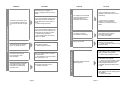
1
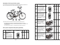
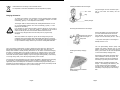
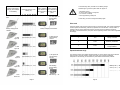
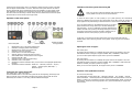
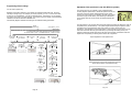
 Congratulations!
OPERATING
INSTRUCTIONS
Congratulations on your decision to buy a product manufactured by KTM. We are sure that
your new Pedelec will more than fulfil your expectations in function, design and quality, both
now and in the future.
All KTM Pedelecs are manufactured under the latest production methods and with high
quality materials and are equipped with the best components according to their function.
We would like you to read this guide carefully so that you can experience untroubled
driving pleasure with your new Pedelec by KTM.
Please make sure that your new Pedelec is handed over to you from KTM
completely assembled, adjusted, and with all instructions.
This manual is a supplement to the KTM Bike Pass.
Should you have any questions after reading the manual, please contact your KTM dealer.
DRIVE SYSTEMS
Safety and Performance
- Please follow all national road laws and regulations.
- Make sure that frame size and controls are matched to your body height.
- Check before driving whether the brakes, lights and other safety-related components are
functional and free of defects.
- Never drive without the lights on at night!
- Never carry a passenger on your bike (Exception: carrying a small child in a special child
seat).
- Please note that the driving characteristics may change dramatically under load.
- Always wear a helmet!
English
Page 1
Congratulations!
OPERATING
INSTRUCTIONS
Congratulations on your decision to buy a product manufactured by KTM. We are sure that
your new Pedelec will more than fulfil your expectations in function, design and quality, both
now and in the future.
All KTM Pedelecs are manufactured under the latest production methods and with high
quality materials and are equipped with the best components according to their function.
We would like you to read this guide carefully so that you can experience untroubled
driving pleasure with your new Pedelec by KTM.
Please make sure that your new Pedelec is handed over to you from KTM
completely assembled, adjusted, and with all instructions.
This manual is a supplement to the KTM Bike Pass.
Should you have any questions after reading the manual, please contact your KTM dealer.
DRIVE SYSTEMS
Safety and Performance
- Please follow all national road laws and regulations.
- Make sure that frame size and controls are matched to your body height.
- Check before driving whether the brakes, lights and other safety-related components are
functional and free of defects.
- Never drive without the lights on at night!
- Never carry a passenger on your bike (Exception: carrying a small child in a special child
seat).
- Please note that the driving characteristics may change dramatically under load.
- Always wear a helmet!
English
Page 1
Description of the Panasonic drive system
Identification
Your KTM Pedelec is an EPAC (Electrically Power Assisted Cycle) according to EN15194 and
differs in the following points from a bicycle without drive assistance:
2
or
or
36V
36V RT
X*
X*
25V
Sanyo Li-Ion Technology
36 V / 12 Ah – 432 Wh
(3.6 kg), full charging in about
4 hours, at least 500 charging
cycles possible
Original Panasonic Battery
25 V / 12 Ah – ID System
3
or
or
Sanyo Li-Ion Technology
25 V / 12 Ah – 302 Wh
(2.8 kg), full charging in about
4 hours, at least 500 charging
cycles possible
X
Centre Motor 36V
KTM basically installs three different Panasonic drive systems (Model year 2012)
-
System System System
Original Panasonic Battery
36 V / 12 Ah – ID System
or
-
Illustration
36V Centre Motor Drive System – in combination with an idling free wheel hub
36V Centre Motor RT Drive System with the coaster brake function - in combination with
a coaster brake hub
25V Centre Motor Drive System – in combination with an idling free wheel hub
4
brushless DC motor, voltage
level 36 V – high efficiency,
nominal power 250 W,
nominal torque 21 Nm,
torque sensor on the pedal
bearing axis
X
Centre Motor 36V with backstep braking function
Drive system components and system applicability
Identification
1
Illustration
5
System System System
36V
36V RT
25V
Original Panasonic
Battery 36 V / 14 Ah –
ID System
brushless DC motor, voltage
level 36 V – high efficiency,
nominal power 250 W,
nominal torque 21 Nm,
torque sensor on the pedal
bearing axis
X
Centre Motor 25V
Sanyo Li-Ion Technology
36 V / 14 Ah – 504 Wh
(4.4 kg), full charging in
about 5 hours, at least 500
charging cycles possible
X*
Page 2
X*
6
brushless DC motor, voltage
level 25 V – high efficiency,
nominal power 250 W,
nominal torque 21 Nm,
torque sensor on the pedal
bearing axis
X
Page 3
Identification
Illustration
System System System
36V
36V RT
25V
System System System
Identification
7
9
10
36V
36V RT
X
X
25V
36V fast charger
X
Speed sensor
Special charger for charging
Li-Ion batteries, suitable for
100 – 230 V 50/60 Hz power
supply line output voltage,
output voltage 42.0 V, output
current 4.1 A, output power
195 W
X
LED control panel
8
Illustration
25V fast charger
LED display with backlight,
3 levels of assistance 50 /
120 / 200 %, charging level
display, current support
X*
LCD control panel
LCD display with backlight,
3 levels of assistance 50 /
120 / 200 %, charging level
display, current support /
current speed / odometer /
trip / average speed
X*
X*
X*
X*
X*
Special charger for charging
Li-Ion batteries, suitable for
100 – 230 V 50/60 Hz power
supply line output voltage,
output voltage 29.3 V, output
current 4.0 A, output power
140 W
X
Compatibility of Panasonic drive systems 36V and 25V
The drive components of the 36V drive system and of the 25V drive system
are not compatible and they are secured against interchange. Never try to
use incompatible drive components – this could result in danger for you and
for other persons. Furthermore, the entire warranty and guarantee claims
expire.
WARNING
X** X** X**
Padlock Ring
To charge your batteries, use exclusively only the provided power supply
supplied with the bike. Using third party or unsuitable chargers can cause
overheating, ignition, or even explosion of the battery.
To avoid mixing up the different batteries, there are different battery holders installed in the
36V system and 25V system. A tab on the battery holder of the 36V drive system prevents
insertion of an incorrect battery. The tab is also situated on the 36 V charger.
36V system battery holder 25V system battery holder
* Depending on configuration, the various batteries and control panels are selected
differently by KTM. The X shows the compatibility of the components with the respective
system
** Special KTM Pedelec models are supplied without padlock ring
Page 4
Page 5
Identification
Illustration
System System System
36V
36V RT
25V
System System System
Identification
7
9
10
36V
36V RT
X
X
25V
36V fast charger
X
Speed sensor
Special charger for charging
Li-Ion batteries, suitable for
100 – 230 V 50/60 Hz power
supply line output voltage,
output voltage 42.0 V, output
current 4.1 A, output power
195 W
X
LED control panel
8
Illustration
25V fast charger
LED display with backlight,
3 levels of assistance 50 /
120 / 200 %, charging level
display, current support
X*
LCD control panel
LCD display with backlight,
3 levels of assistance 50 /
120 / 200 %, charging level
display, current support /
current speed / odometer /
trip / average speed
X*
X*
X*
X*
X*
Special charger for charging
Li-Ion batteries, suitable for
100 – 230 V 50/60 Hz power
supply line output voltage,
output voltage 29.3 V, output
current 4.0 A, output power
140 W
X
Compatibility of Panasonic drive systems 36V and 25V
The drive components of the 36V drive system and of the 25V drive system
are not compatible and they are secured against interchange. Never try to
use incompatible drive components – this could result in danger for you and
for other persons. Furthermore, the entire warranty and guarantee claims
expire.
WARNING
X** X** X**
Padlock Ring
To charge your batteries, use exclusively only the provided power supply
supplied with the bike. Using third party or unsuitable chargers can cause
overheating, ignition, or even explosion of the battery.
To avoid mixing up the different batteries, there are different battery holders installed in the
36V system and 25V system. A tab on the battery holder of the 36V drive system prevents
insertion of an incorrect battery. The tab is also situated on the 36 V charger.
36V system battery holder 25V system battery holder
* Depending on configuration, the various batteries and control panels are selected
differently by KTM. The X shows the compatibility of the components with the respective
system
** Special KTM Pedelec models are supplied without padlock ring
Page 4
Page 5
Removing the Panasonic batteries:
Use only genuine Panasonic components
Only genuine Panasonic drive components and Panasonic original
batteries are installed in KTM Pedelecs. Therefore, use exclusively only
Panasonic original drivetrain components and genuine batteries for
retrofit and replacement purposes.
WARNING
The use of third party or unsuitable drivetrain components and/or
batteries can cause overheating, ignition, or even explosion of the
batteries. It also invalidates any guarantee and warranty claim.
- Hold the battery and simultaneously turn the key 90 degrees counter-clockwise
- Slowly pull the battery in your direction. (The key remains in the open position. In this
position, it cannot be pulled out.)
- Hold the battery pack in both hands so that you can remove it safely. Then turn the key 90
degrees clockwise and pull it out.
Installing and removing the batteries
Installing the Panasonic batteries:
Insert the battery from above at an angle into
the battery holder
(The battery level indicator must be on the side
of the battery facing you.)
WARNING
After removing the batteries, remove the key and keep it safely. Hold the
battery while you turn the key, otherwise the battery may release from the
holder.
Handling and charging the batteries
WARNING
Tilt the battery upwards until it engages in
the lock.
WARNING
Page 6
Make sure by pulling the battery, that
it is securely locked, otherwise the
battery may be released from the
holder.
Never short-circuit the battery by connecting the terminals. This could lead to
overheating, ignition, or even explosion of the battery. Never try to open the
battery. This could lead to a short circuit and in consequence to overheating,
ignition, or even explosion of the batteries. The battery may not be serviced
by the user. If the battery cover is opened, all warranty and guarantee claims
expire.
Do not use any batteries which have the case or plug obviously damaged.
Make sure that the fully charged battery, after completed charging, is no longer
connected to the charging power supply. The Lithium Manganese battery cells used have
minimal self-discharge, therefore, no permanent connection with the battery charger is
necessary. Basically, it is quite sufficient to charge the battery every three months. Before
long periods of inactivity (e.g. before a winter break), we recommend that the battery be
fully charged and then subsequently every three months.
It is best to store the unused batteries in a cool place at temperatures between 5 °C and
25 °C. Never charge the batteries in places where the temperature may be above 45 °C
or below minus 20 °C. The battery should never be exposed to extreme temperature
fluctuations or humidity and it is essential to protect it from moisture during storage to
prevent corrosion on the plug contacts.
Never let the battery drop and protect it from mechanical damage. Damage could lead
to a short circuit and in consequence to overheating, ignition or even explosion of the
batteries.
Page 7
Used batteries do not belong in the household refuse!
It is important to note that used batteries must be disposed of properly!
Inserting the batteries into the charger:
220 – 240V
Plug
Charging the batteries
To charge your batteries, use exclusively only the provided charger supplied
with the bike. The use of third party or unsuitable chargers can cause
overheating, ignition, or even explosion of the battery.
WARNING
Plug the charger into the wall socket (220 240 V) and insert the battery into the
charger.
The charger shall be used exclusively with rechargeable batteries. The use
of non-rechargeable batteries can cause overheating, ignition, or even
explosion of the battery.
It is necessary to ensure that the battery and the charger do not get wet or
damp during charging or when the charger is connected to the network
and/or turned ON, so as to avoid electrical shocks and short circuits.
Do not use any chargers which have the cable, case or plug obviously
damaged.
Allow only children over 8 years of age to use the charger and give the
respective child corresponding safety and detailed instructions for charging
the batteries. Make it explicitly clear to the respective child that the charger is
no toy and that the charger should only be used for rechargeable batteries.
The Li-Ion battery employed has no memory effect and it also does not to have be fully
discharged and charged. We recommend charging the battery after each ride, if the
battery level indicator is already showing less than 50 %. We further recommend charging
the battery completely before long periods of inactivity, for example before a winter break.
It is best for your battery to be emptied during the first three charging cycles, to such an
extent that the battery indicator displays only one LED (light emitting diode). If the battery
is no longer being used, it must be fully charged every three months.
Battery Charger
Removing the batteries from the charger:
Pull down and remove,
while the charger is
firmly held.
* The power consumption of the charger in
standby mode is 1.5 W.
Checking the battery charging
level:
The red light-emitting diodes (LEDs) will
indicate the battery charging level on the
battery (5 LEDs) and on the control panel (3
LEDs). (The number of the LEDs lit depends
on the current battery charging level.)
With the drive system ON, the battery level
will be indicated on the control panel. The
battery charging level may be indicated on
the battery by pressing the "PUSH" button.
Too high and too low temperatures are very bad for the battery, especially during charging.
It is necessary to avoid charging batteries in direct sunlight or on heaters! This will
significantly reduce the battery life. We therefore recommend charging the battery pack in
temperatures of approximately 20 °C. After a ride in a cold environment, the battery should
first be warmed to room temperature (20 °C) before charging.
Battery charging level indicator
on the battery
Page 8
Remove the battery from the charger after
you have verified that all LEDs are not lit
(fully charged). Now you can unplug the
charger from the wall outlet (AC 220 - 240 V).
While charging (the battery seated in the
charger – see "Charging the batteries"), the
current charging level will be indicated
through the five red LEDs on the battery. If
the battery is fully charged, all five LEDs go
OFF.
Page 9
Status of the battery
charging level indicator
on the battery
Remaining capacity of the
battery (%)
In the following cases, the LEDs on the battery charge
indicator light up, but the system does not support it:
Status of the
Status of the
battery charging battery charging
level indicator on level indicator on
the LCD control the LED control
panel
panel
ATTENTION
Button for battery charging
level
All 3 LEDs light red
approximately:
100-70%
In this case, you have to charge the battery again.
Drive mode
approximately: 100 - 80%
Battery charging level
indicator
4 LEDs
light red
3 LEDs
light red
The drive system works in three levels of support in the Drive mode. They will be supported by
the drive system automatically, without any operation of an accelerator. A torque sensor is
located in the axis of the pedal bearing and it measures the force applied by the driver.
According to the measured force, the power of the supporting electric motor will be regulated
accordingly.
Battery charging level indicator
approximately: 80 - 60%
- The battery is new
- It has not been used for a long time
– It is used on a cold day
– When approaching a steep hill
2 LEDs light red
approximately:
70-40%
approximately: 60 - 40%
Support step (gear) (A)
Support level
Driving situation
1
50%
Driving on the flat
2
120%
Gradients, headwinds
3
200%
Steep hills,
strong headwind
Expected maximum range
2 LEDs
light red
approximately: 40 - 20%
1 LED
lights red
approximately: 20 - 10%
1 LED lights red
approximately:
40-10%
The maximum range of the battery depends greatly on various factors such as the selected
level of support, the road surface, weight of the rider, tyre pressure and ambient
temperature. The following are the maximum performance characteristics possible:
Battery 36 V / 14 Ah
Slow blinking
approximately:
10-0%
Battery 36 V / 12 Ah
Battery 25 V / 12 Ah
1 LED
blinks red
approximately: 10 -0%
Page 10
Fast blinking → off
Page 11
Concerning the driving feeling, there is no difference whether the drive system is operated
with the support switched OFF or on level 0. When the drive system with the LCD control
panel is switched ON, all the speedometer functions are available. The drive system works
most effectively at a cadence of 60 revolutions per minute. We recommend selecting the
drive level at all times according to actual needs, since the effectiveness of the drive system
increases with the correct choice of the support level.
Calibration of the drive system when turning ON
Operation of the drive system
To allow the drive system to react properly to your pedal pressure, this automatically
performs a calibration during the first two seconds after power ON. During this process, the
torque applied on the pedal bearing is determined and it is reset to the zero starting value.
Never turn the drive system ON and OFF with pressure exerted
on the pedals! This may result in functional failures!
ATTENTION
If you now place pressure on the pedal during power up, the drive
system measures the wrong value and, it can then subsequently
react improperly – an error is indicated. This will be indicated in the
Pedelec with LED control panel by alternating flashing of all LEDs of
the support levels and of all LEDs of the battery charging level; in
the Pedelec with LCD control panel, by the E1 error signal.
LED control panel 1 2 3 4 5 6 7 8 9 10 11 12 LCD control panel
Example of display
during operation
POWER button to turn the system ON and OFF
Indication of charging status of the batteries
MODE button for setting the support level
Indication of the level of support
LIGHT button to turn OFF the backlight
Assist UP button to increase the level of support
Assist DOWN button to decrease the level of support
Indicator light ON or OFF
Indication of the current consumed energy
Indication of the current speed
Speedometer function indication value (current value for the displayed speedometer
function)
Speedometer function indication: TOTAL KM … odometer / TRIP KM... Trip km /
O KM/H … Average speed / MAX-KM/H … /
Maximum speed
In this case, you should turn the drive system OFF once more and ON again with the
POWER button, without exerting pressure on the pedals –in this way, the error should be
corrected.
Adjusting the levels of support
LED control panel:
By pressing the Assist button UP or DOWN, the support level can be adjusted. There are
three different levels of strength of support available: ECO / STANDARD / HIGH. When
you turn the drive system ON, the support level is pre-set to STANDARD.
LCD control panel:
By pressing the Assist button UP or DOWN, the support level can be adjusted. There are
three different levels of strength of support available: ECO / STANDARD / HIGH. When NO
ASSIST is indicated, the system provides no support.
When you turn the drive system ON, the support level is pre-set to STANDARD.
Operation of the speedometer functions
Turning the drive system ON and OFF
LED control panel + LCD control panel:
Press the POWER button to turn the drive system ON. At the beginning, all LEDs light red;
after two seconds, the current battery charging level and the support mode set will be
indicated by the red LEDs. To turn OFF, press the POWER button again.
Page 12
For LCD control panel only:
The speedometer functions TOTAL KM … odometer/ TRIP-KM … Trip / O KM/H … Average
speed / MAX-KM/H … Maximum speed will be displayed under the speed readout on the LCD
display. To switch from one function to another, press the MODE button briefly; to reset the
trip odometer, travel time and average speed to zero, press the MODE key for longer than
three seconds.
Page 13
Programming of basic settings
Adjustment of the speed sensor (only with 36V drive systems)
For LCD control panel only:
The good function of your Pedelec is only guaranteed with a
correctly adjusted speed sensor. Should the speed sensor be set
incorrectly, the drive system makes significant errors visible
through the control panel. In the Pedelec with LED control panel,
the current support level flashes, thus indicating a malfunction;
in the Pedelec with LCD control panel, the display indicates the
E2 error.
Basically, all the basic settings for your Pedelec are optimally selected by KTM. However,
should you change a tyre, for example, for service purposes, you can – to ensure the exact
function of your speedometer – set the tyre diameter anew. Furthermore, you can change
the setting of the control console language, the contrast of the LCD display, the speedometer
indication unit and the odometer indication unit.
The following diagram illustrates the setting of the individual setting parameters:
NORMAL
OPERATING MODE
The speed sensor is set correctly when the spoke magnet is located just above the notch of
the speed sensor (see Illustration). The spoke magnet should always be aligned so that it
is situated right in the intersection area of the spokes, so that it cannot twist (see
Illustration). The adjustment of the speed sensor is done through two fixing screws on the
lower side of the left chain stay (see illustration). By loosening the locking screws, it is
possible to adjust the speed sensor along the chain stay forwards or backwards. After the
adjustment is completed, the locking screws should be re-tightened.
Normal operating mode
Setting mode
To exit the setting mode (from all levels) press the LIGHT button.
To enter the setting mode, press MODE & for longer than 3 seconds.
SETTING THE
LANGUAGE
MODE
SETTING THE
LANGUAGE
WITH
AND
SETTING THE
LCD CONTRAST
MODE
SETTING THE
LCD CONTRAST
WITH
AND
SETTING KM /
MILE
TYRE SIZE
ADJUSTMENT
MODE
Proper adjustment of the speed sensor
SETTING TOTAL
KILOMETRES
MODE
SETTING
KM / MILES
WITH
AND
TYRE SIZE
ADJUSTMENT
4. SET
WITH
AND
SETTING TOTAL
KILOMETRES 6. SET
WITH
AND
MODE
SETTING
TYRE SIZE
3. SET
WITH
AND
MODE
SETTING
TYRE SIZE
2. SET
WITH
AND
MODE
SETTING
TYRE SIZE
1. SET
WITH
AND
MODE
SETTING TOTAL
KILOMETRES 5. SET
WITH
AND
MODE
MODE
MODE
SETTING TOTAL
KILOMETRES 4. SET
WITH
AND
MODE
Proper placement of the spoke magnet and mounting
screws at the bottom of the left chain stay
SETTING TOTAL
KILOMETRES 3. SET
WITH
AND
MODE
SETTING TOTAL
KILOMETRES 2. SET
WITH
AND
MODE
SETTING TOTAL
KILOMETRES
1. SET WITH
1. SET 4. DIGIT
Page 14
▼ AND ▲
1. SET
6. SET
Page 15
Maintenance and Care
ATTENTION
Regularly check the tightness and seating of the nuts holding the rear
wheel hub and the bolt for the engine support for models with the
coaster brake. The nuts holding the rear wheel hub must be tightened
to 20 Nm (= VERY FIRMLY!). Compliance with this tightening torque is
essentially required for the proper function of the drive. It is strongly
recommended that the mounting nuts and bolt for the engine support
are checked and re-tightened immediately after the first 10 km of
receipt of the bike, since the screw connections must be allowed to
settle in the new bike.
Pay attention to the chain tension when using a model that is equipped with a drive system
with a coaster brake function – too little tension of the chain can negatively affect the
braking performance of the coaster brake.
We recommend checking by the dealer of the spoke tension of the wheels and all bolted
connections (including the motor screw connections) after the first 200 km. It should
also be noted that shorter maintenance intervals should be complied with for Pedelecs
than for regular bicycles because of higher loads. Your dealer will gladly provide you with
the relevant advice.
To maintain the lasting and good functionality of the drive system, all plug contacts of the
drive system should be reviewed every two to three months and, if necessary, cleaned with
a soft dry brush. It must be ensured that no dirt or moisture gets into the battery holder.
The electric motor is a brushless DC motor, which does not have to be serviced.
Cleaning
ATTENTION
Never use a pressure washer to clean the drive system. A strong
jet of water could damage the electrical components of the drive
system!
We recommend cleaning the bike with a soft sponge or a soft brush. To clean the battery
holding rail, use a damp cloth. Always work with a little water and keep water away from
the electrical contacts. After cleaning, check the connectors for moisture and let them dry if
necessary before re-starting the bike.
Page 16
Transport of the Pedelec on a car roof rack or rear rack
WARNING
Please pay attention that the employed car rear or roof carrier is also suitable
for the increased weight and that it is specifically intended for the special
frame shape of the Pedelec. An unsuitable carrier can be damaged or broken
during the transportation of the Pedelec and it therefore represents a great
danger! In addition, the Pedelec itself may be damaged by an unsuitable car
rear or roof carrier.
In principle, we recommend that you remove the battery and protect the plug contacts
from contamination when transporting the Pedelec on a car rear or roof carrier.
Appropriate protective caps are available from your dealer.
Repairs and Spare Parts
Refer all repairs of the drive system to the trained specialists of
your dealer. All original spare parts for your Pedelec may be
obtained from your KTM dealer. Should you need spare keys for
the battery lock, please also contact your local dealer – therefore,
make a note of the key number for this eventuality.
Troubleshooting
SOLUTION
SYMPTOM
Is the battery charged? Has the battery
not been used for a long time?
=> Please charge the battery.
THE RANGE OF THE BATTERY IS LOW
Was the battery used for the first time?
=> Please charge the battery.
The range could be reduced by the road
surface conditions, gear selection or by
erratic driving behaviour.
The LEDs for the battery
charging level on the control
panel blink after a short ride.
The decrease in range is normal in
winter due to the low temperatures.
Is the air pressure in the tyre too low?
=> Please pump air into the tyre.
Is the brake properly adjusted?
=> The brake should be properly
adjusted by your dealer.
Page 17
SYMPTOM
SYMPTOM SOLUTION
If you press the battery charging level
button and the 2nd and 4th LEDs are
lit, the safety device of the battery is
active.
=> Please charge the battery.
The LEDs for the support mode
or for the battery charging level
on the control panel do not light
up.
If you press the battery charging level
button and none of the LEDs is lit, the
safety device of the battery is active.
=> Please charge the battery.
* If the problem cannot be resolved,
contact your dealer.
During overloading, the system
operates in safe mode due to current
overheating.
The charging level LEDs blink
three times and the support
mode LED blinks once,
alternating with each other.
* In safe mode, the support is
limited, if the normal function
condition is not restored, ask your
dealer.
Is the cabling loose or are the
connectors contaminated?
=> Contact your dealer.
The system is turning
automatically ON and OFF.
Does this happen after you have been
stationary for five minutes?
=> System in idle state, please turn the
system ON again.
Support turned OFF.
The charging status LEDs blink
fast or do not light up at all.
Is the battery charged?
=> Please charge the battery.
Were you pedalling while you turned
the system ON?
=> See calibration of the drive system
while turning ON (P. 13)
The LEDs for the charging
level and support mode
blink alternately.
The charging status LEDs blink
twice and the support mode
LED blinks once, alternating
with each other.
The system could have an error.
=> Contact your dealer.
Page 18
THE BATTERY DOES NOT CHARGE
THE DRIVE SYSTEM PROVIDES NO SUPPORT
THE DRIVE SYSTEM PROVIDES NO SUPPORT
Is the battery fully engaged? =>
Please re-engage the battery into the
holder.
SOLUTION
Is the battery properly engaged? Are the
battery contacts contaminated?
=> Please clean the battery contacts.
Is the battery fully charged?
=> Check the remaining battery capacity
by pressing the charging level button.
A fully charged battery cannot be
re-charged. Charge the battery after it
is used.
The battery charging level LED
does not light up.
Was the battery level button pressed
while pedalling, and the charging status
LED blinked?
=> Contact your dealer.
Page 19
SYMPTOM
SOLUTION
Information on warranty and guarantee
The charger is warm during the charging
process.
=> Normal behaviour of the charger.
Battery and / or charger become hot
(Remember that the battery and / or
charger may ignite)
The warranty and guarantee provisions specified here are complementary to the KTM Bike
Pass in terms of the features of the Pedelec drive components listed below.
For motor and control unit, the warranty legally valid at the time of shipment applies.
Is the charger so hot that it is impossible
to touch?
=> Immediately stop usage and contact
the dealer. Provisions for the batteries of the KTM Pedelec:
Was the battery removed while charging?
=> Please re-charge the battery. Is the connector of the charger
contaminated? => Please clean the
connector.
None of the five battery charging level
LEDs lights up after charging.
1.
The guarantee applies only to material or workmanship defects and only upon
presentation of the proof of purchase consisting of an original sales receipt or cash
receipt with the specified date of purchase, dealer's name and model number of the
bike in which the battery is used, for two years from date of purchase. KTM
reserves the right to refuse the warranty service if the documents submitted with
the battery are incomplete.
2.
In the case of a warranty, KTM undertakes to repair the claimed batteries or, at the
discretion of KTM, to replace with the equivalent replacement or spare part.
3.
Warranty repairs will be performed in the premises of KTM. Costs for repairs which
were performed at a location not previously approved by KTM, will not be refunded.
In this case, the warranty will be void.
4.
Repair services or replacement during the warranty period do not entitle the owner
to an extension or to a restart of the warranty period. Repairs and direct
replacement under warranty can be performed with functionally equivalent
replacement units.
Is the battery already quite old and is it
used very often?
=> The battery life may be at an end.
The guarantee does not apply if defects other than defects of material or workmanship
are found.
The following items are NOT covered by warranty:
You feel vibrations when you place
a foot on the pedal when stationary.
These are the characteristics of the motor.
Page 20
1.
Testing, maintenance, repair and replacement service on the basis of normal usage
2.
If the battery does not reach the full capacity based on normal usage.
3.
By improper use: The product was exposed to liquids / chemicals of any kind and/or
to extreme temperatures, moisture or humidity. Damage of the battery by ignoring
the special instructions in the chapter: "Handling and storage of the battery" or the
chapter "Use only Panasonic original components".
Page 21
Information on warranty and guarantee The warranty and guarantee provisions specified here are complementary to the KTM Bike Pass in terms of the features of the Pedelec drive components listed below. For motor and control unit, the warranty legally valid at the time of shipment applies. 4. The model number, serial number or product number on the product has been changed,
Provisions for the batteries of the KTM Pedelec: erased, made illegible or removed. The seal on the battery case has been broken or
1. The guarantee applies only to material or workmanship defects and only upon obviously tampered with.
presentation of the proof of purchase consisting of an original sales receipt or cash receipt 5. Use of batteries in systems which are not permitted to be used with this product (the
batteries may be used only in the product which they were shipped with).
with specified date of purchase, dealer's name and model number of the bicycle, in which the battery is used, for two years from date of purchase. KTM reserves the right to refuse the 6. Accidents, acts of God or causes beyond the control of KTM, caused by water, fire, public
disturbances or inadequate use (humidity).
warranty service if the documents submitted with the battery are incomplete. 2. In the case of a warranty, KTM undertakes to repair the claimed batteries or, at the 7. Damage of the batteries by overcharging or failure to comply with the special instructions
for handling the batteries (see User Information).
discretion of KTM, to replace with the equivalent replacement or spare part. 8. The batteries were recharged with chargers that do not belong to the drive system.
3. Warranty repairs will be performed in the premises of KTM. Costs for repairs which were performed at a location not previously approved by KTM, will not be refunded. In this 9. Unauthorised modifications made to the product, by which the product does not comply
with local or national technical standards in the countries for which the product was
case, the warranty will be void. originally released by KTM.
4. Repair service or replacement during the warranty period do not entitle the owner to 10. Less power (less than 70%) of the battery if it has been completely charged and
an extension or to a restart of the warranty period. Repairs and direct replacement under discharged more than 500 times within the warranty period of two years.
warranty can be performed with functionally equivalent replacement units. The guarantee does not apply if defects other than defects of material or workmanship are found. The following items are NOT covered by warranty: 1. Testing, maintenance, repair and replacement service on the basis of normal usage Warranty disclaimer:
2. If the battery does not reach the full capacity based on normal usage. KTM shall not be liable for property damage, downtime, pawn or rental equipment, travel
3. By improper use: The product was exposed to liquids / chemicals of any kind and/or expenses, lost profits or similar. The liability of KTM is limited to the purchase price of the
to extreme temperatures, moisture or humidity. Damage of the battery by ignoring the product.
special instructions in the chapter: "Handling and storage of the battery" or the chapter "Use The rights of the purchaser according to the applicable national legislation, that is, which are
only Panasonic original components". derived from the purchase contract of the buyer towards the seller as well as other rights, will
not be affected by this warranty. This warranty is the sole and exclusive remedy of the
purchaser and neither KTM nor its subsidiaries are liable for incidental or consequential
damages or injury to any statutory or contractual warranty obligations for this product.
With regard to the rest of the bike components, the provisions specified in the KTM
Bike Pass apply.
KTM FAHRRAD GMBH
Page 22
OPERATING INSTRUCTIONS
PANASONIC DRIVE SYSTEMS
Specifications subject to change.
No liability for mistakes and misprints.
Rev.: Fall 2011
ART. No.:
00012000011
KTM FAHRRAD GMBH
Harlochner Straße 13 5230 Mattighofen Austria