Download weatherpak 2000 shipboard manual
Transcript
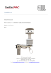
WEATHERPAK-2000 MANUAL Version 3.0 Shipboard Weather System August 2006 COASTAL ENVIRONMENTAL SYSTEMS 820 First Avenue South, Seattle, Washington 98134 Telephone: 206-682-6048 1-800-488-8291 Fax: 206-682-5658 Coastal Environmental Systems (206) 682-6048 1 WEATHERPAK-2000 User Manual Shipboard Weather REVISIONS Version 1.0 2.0 3.0 Description Initial Release Added sensor specification sheets Added sections for ultrasonic wind monitor and AT/RH sensor Coastal Environmental Systems (206) 682-6048 Date 11/99 05/04 08/06 2 WEATHERPAK-2000 User Manual Shipboard Weather TABLE OF CONTENTS REVISIONS LIST OF FIGURES 1.0 INTRODUCTION 1.1 THE SYSTEM 2.0 UNPACKING AND IDENTIFICATION 2.1 THE WEATHERPAK-2000 2.2 THE BASE MOUNT 2.3 THE BRIDGE INTERFACE/DISPLAY BOX 2.4 POWER SUPPLY 3.0 INSTALLATION 3.1 INSTALLING THE WEATHERPAK-2000 CABLE 3.2 INSTALLING THE BASE MOUNT 3.3 INSTALLING THE BRIDGE EQUIPMENT 3.4 INSTALLING THE WEATHERPAK-2000 4.0 VERIFYING SYSTEM OPERATION 4.1 VERIFY THE WEATHERPAK-2000 AND DISPLAY OPERATION 4.2 VERIFY MEASUREMENT ACCURACY 5.0 MAINTENANCE 5.1 SCHEDULED SERVICE 5.1.1 WEATHERPAK-2000 MAINTENANCE 5.1.2 WIND SENSOR MAINTENANCE 5.1.3 TEMPERATURE/RH SENSOR MAINTENANCE 5.1.4 BAROMETER MAINTENANCE 5.1.5 CABLES AND CONNECTOR MAINTENANCE 5.1.6 DISPLAY UNIT MAINTENANCE 5.2 UNSCHEDULED MAINTENANCE 5.2.1 TROUBLESHOOTING INSTALLATION PROBLEMS 5.2.2 TROUBLESHOOTING DISPLAY FAILURE 5.2.3 TROUBLESHOOTING SENSOR FAILURE 5.3 LINE ITEM REPLACEMENT 6.0 SHIPBOARD WEATHER 6.1 A LITTLE MARINE METEOROLGY 6.2 SHIP INDUCED ERRORS 6.3 CONTAMINATION BY SALT 7.0 DATA AVERAGING METHODS 8.0 AUTOMATIC BOOTUP SEQUENCE 9.0 DATA SPECIFICATIONS 9.1 CHANNEL ONE (DISPLAY OUTPUT): 9.2 CHANNEL TWO (NMEA OUTPUT): 10.0 PROBLEM REPORTING AND QUESTIONS Coastal Environmental Systems (206) 682-6048 2 5 7 7 13 13 15 17 20 21 22 23 24 25 26 27 28 30 30 30 31 31 31 31 31 32 32 32 34 37 40 42 43 48 50 51 52 52 52 54 3 WEATHERPAK-2000 User Manual Shipboard Weather APPENDIX A PARTS LIST APPENDIX B SCHEMATICS AND WIRING DIAGRAMS APPENDIX C SENSOR SPECIFICATIONS APPENDIX D GLOSSARY Coastal Environmental Systems (206) 682-6048 58 59 61 68 4 WEATHERPAK-2000 User Manual Shipboard Weather LIST OF FIGURES Figure 1A: Shipboard WEATHERPAK-2000 Block Diagram (Single WEATHERPAK) Figure 1B: WEATHERPAK-2000 System Block Diagram (Dual WEATHERPAKs) 9 10 Figure 2: WEATHERPAK-2000 Nomenclature (Shown with R.M. Young Wind Monitor) 11 Figure 3: Dimensional Drawing 14 Figure 4: Quick –Release Base Mount 15 Figure 5: Base Mount Connector 16 Figure 6: The Bridge Interface/Display Box 18 Figure 7: Bridge Interface/Display Box Connections 19 Figure 8: Power Supply 20 Figure 9: Bow of Ship 23 Figure 10: Replacing the RH Filter 39 Figure 11: The Wind Flow Around a Ship. 43 Figure 12: The Temperature Distribution Around a Ship. 44 Figure 13: The RH Distribution Around a Ship. 46 Figure 14: The Pressure Distribution Around a Ship. 47 Coastal Environmental Systems (206) 682-6048 5 WEATHERPAK-2000 User Manual Shipboard Weather IMPORTANT NOTES • CALL/FAX US IF YOU HAVE QUESTIONS OR PROBLEMS. Call Coastal Environmental Systems if any troubles arise or if you have any questions pertaining to the equipment. Our telephone number is 206-6826048 and the FAX number is 206-682-5658. • KEEP THE TERMINAL CONNECTION COVERED When the WEATHERPAK-2000 has been removed, the base mount connector is exposed to contamination or rain. Use the protector cap (Figure 2) to prevent damage to the base mount. • USE LUBRIPLATE ON BOLTS All bolts should have their threads treated with Lubriplate before tightening. This prevents galling, retards corrosion, and assures post deployment removal. • KEEP THE HUMIDITY SENSOR CLEAN The humidity sensor is susceptible to contamination from salt spray and exhaust deposits. If the installation is in a location where contamination is suspected, then regular cleaning is required for quality data. The humidity sensor comes with a protective filter over the sensor head. This filter will prevent dirt and salt spray from reaching the sensor element. The filter should be checked and cleaned at routine intervals. • PROTECT CONNECTORS FROM CORROSION All connectors, with the exception of molded underwater connectors, are liable to leak or corrode after prolonged exposure to the weather. For a long term installation, all connectors should be taped with one or two layers of self-vulcanizing tape followed with a protective outer coating of all-weather black electrical tape. Coastal Environmental Systems (206) 682-6048 6 WEATHERPAK-2000 User Manual Shipboard Weather 1.0 INTRODUCTION The components and data outputs of a WEATHERPAK-2000 system will vary depending upon the needs of the customer. For example, a customer that wants to measure air quality will have a different sensor suite than a customer that wants to measure wave action and water salinity. Also, of two customers that want to measure the same conditions, one might only want to view the data in real time, using preset measurement parameters; the other might want real time data and additionally want a two-way communications system with which he can change parameters and modify measurement timing. This manual has mostly generic information in the main chapters. You should become familiar with your system before reading the generic information in the main chapters. You will then know which generic information does or does not apply to your system. For example, if your system does not have a barometer, you can skip the information relating to barometer maintenance in Chapter 5.0 Maintenance. 1.1 THE SYSTEM The WEATHERPAK-2000 Shipboard Weather System is typically made up of the following major components: 1. One or two Shipboard WEATHERPAK-2000s In waterproof canister with the following sensors: (a) Wind monitor (optional ultrasonic wind sensor) for wind speed and direction, (b) Air temperature sensor, (c) Relative humidity sensor, (d) Barometer 2. Quick-release base mount for each WEATHERPAK-2000 With umbilical cable connection. A protective cover is provided with the base mount. 3. Mating connectors For customer furnished umbilical extension cable. 4. Bridge interface/display box To connect the WEATHERPAK-2000 to the Bridge Navigation System (BNS) and to the panel display. 5. Power Supply To power the system via the interface unit. Coastal Environmental Systems (206) 682-6048 7 WEATHERPAK-2000 User Manual Shipboard Weather The WEATHERPAK-2000 has two output channels for serial data: Channel 1 – to the display Channel 2 – to the navigation system The WEATHERPAK-2000s operate automatically upon power-up with no operator or host intervention. There are no host or operator commands necessary for using the system. If you have a two WEATHERPAK® system then the display may have a manual override switch which allows the operator to select which WEATHERPAK will be used to update the display and the Navigation System (otherwise it is assumed to be on “auto-select” for the upwind sensor. The selected WEATHERPAK samples the sensors twice each second. The wind data will be sent out from Channel 2 to the navigation system after each sample (each 0.5 second). The averaged temperature, humidity and pressure data will be sent out Channel 2 every five seconds with the 0.5 second wind data. The averaged wind, temperature, humidity and pressure data will be sent out from Channel 1 to the display every 5 seconds. The display is updated every time it received data from the selected WEATHERPAK-2000. Quick-release base mount The quick-release base mount provides a superb electro-mechanical connection for the WEATHERPAK. The base holds the WEATHERPAK-2000 firmly even after years of use in extreme vibration environments. It is keyed so that when the WEATHERPAKis inserted, it always points in the correct alignment. Umbilical cable A short cable from the base mount terminates in a MS 10-pin (or 17 pin) connector. Mating connectors are provided for ship installation. The customer is responsible for routing the WEATHERPAKto the interface box. Bridge interface/display box The bridge interface/display box is an aluminum box which provides interface for the WEATHERPAKs to the Bridge Navigation System (BNS) and the Coastal Environmental Systems display panel. It distributes 12VDC power the Coastal Environmental Systems (206) 682-6048 8 WEATHERPAK-2000 User Manual Shipboard Weather WEATHERPAK-2000 system. The panel display is a simple digital display of WEATHERPAK-2000 data output. Figure 1A: Shipboard WEATHERPAK-2000 Block Diagram (Single WEATHERPAK) Coastal Environmental Systems (206) 682-6048 9 WEATHERPAK-2000 User Manual Shipboard Weather P/N 2109000041 P/N 2109000005 Figure 1B: WEATHERPAK-2000 System Block Diagram (Dual WEATHERPAKs) Coastal Environmental Systems (206) 682-6048 10 WEATHERPAK-2000 User Manual Shipboard Weather Figure 2: WEATHERPAK-2000 Nomenclature (Shown with R.M. Young Wind Monitor) Coastal Environmental Systems (206) 682-6048 11 WEATHERPAK-2000 User Manual Shipboard Weather 1.2 Viewing the Data There are three ways that data is usually viewed in a WEATHERPAK-2000 system. 1. A display box. Real-time data is formatted and displayed on a small LED screen (or optional large vacuum fluorescent) mounted on a display box – The data is transmitted via hardwire. It is possible to also broadcast WEATHERPAK® data via radio or satellite (if you have ordered the correct transmitters). 2. A computer screen in combination with data display software such as Coastal Environmental System’s INTERCEPT software. 3. A test terminal used for communication that is connected directly to the WEATHERPAK-2000. This requires a test cable that can be supplied by Coastal Environmental Systems. Contact Coastal Environmental Systems for instructions on communicating with a WEATHERPAK-2000. Coastal Environmental Systems (206) 682-6048 12 WEATHERPAK-2000 User Manual Shipboard Weather 2.0 UNPACKING AND IDENTIFICATION Your WEATHERPAK-2000 system is shipped in boxes which should be saved along with copies of the shipping documents to use in case the equipment is returned for service. Open the boxes carefully in a dry area. Remove and identify all of the parts. Handle the components carefully at all times. When properly installed, the equipment can withstand extreme conditions of weather, but rough handling on the ship can break plastic parts or cause damage from undue shock. 2.1 THE WEATHERPAK-2000 The WEATHERPAK-2000 is a versatile compact automatic weather station which has been carefully designed for shipboard applications. Its internal data acquisition electronics are programmed to make the best, most accurate measurements from its sensors; winds are vector averaged and the barometer is read several times and averaged to remove wind, wave, and roll induced errors. All components in the WEATHERPAK-2000 plug together – no tools are required. The wind monitor plugs into a keyed connector on top; the WEATHERPAK plugs in to a locking base mount. The plugs are aligned and keyed to North (relative) and have O-ring waterproof seals. All external parts of the WEATHERPAK-2000 are powder coated, chemically treated aluminum or ultra-violet resistant plastic. All sensor signals and power lines are protected from transients and EMI by circuitry inside the WEATHERPAK-2000. EMI filters are single pole RC filters (100 ohm and 47 picofarads). Transient protection is by 12 volt tranzorb diodes. If for any reason – lightning, RF interference, power surge – the WEATHERPAK-2000 program is corrupted and the sampling loop is broken, a watchdog timer will reset the computer and the WEATHERPAK-2000will resume sampling. Coastal Environmental Systems (206) 682-6048 13 WEATHERPAK-2000 User Manual Shipboard Weather WEATHERPAK with optional ultrasonic wind sensor Figure 3: Dimensional Drawing Coastal Environmental Systems (206) 682-6048 14 WEATHERPAK-2000 User Manual Shipboard Weather 2.2 THE BASE MOUNT The quick release base mount is an electro-mechanical termination for the WEATHERPAK-2000. When the arms are pulled down firmly, the WEATHERPAK-2000 is pulled down onto a rubber gasket inside the mount. This, along with an O-ring on the connector shaft, provides a waterproof seal which will withstand complete submersion in water (although NOT recommended). An alignment pin and slot on the WEATHERPAK-2000 insure that the wind vane is always correctly aligned with the ship axis, provided the base mount is securely and correctly installed. Figure 4: Quick –Release Base Mount Coastal Environmental Systems (206) 682-6048 15 WEATHERPAK-2000 User Manual Shipboard Weather The Base Mount is equipped with a 17-pin connector or optional 10-pin connector. Pins: A GROUND B 11 – 18 VDC Input C COM1 Tx D COM1 Tx + E COM1 Rx - F COM1 Rx + G COM2 Tx – H COM2 Tx + I Spare J Spare 10-pin Connector 17-pin Connector Figure 5: Base Mount Connector Coastal Environmental Systems (206) 682-6048 16 WEATHERPAK-2000 User Manual Shipboard Weather 2.3 THE BRIDGE INTERFACE/DISPLAY BOX The bridge interface/display box is at the center of the WEATHERPAK-2000 Shipboard Weather Station. All of the discrete components are connected to the bridge interface/display box. It distributes power to the system, collects data from the WEATHERPAK, displays selected data on the screen, and passes the NMEA message out to the navigation system. At the heart of the bridge interface/display box is a processor board which controls the display and monitors the WEATHERPAK-2000 data ports. In the dual WEATHERPAK system, a switch is provided on the bridge interface/display box to allow the user to select which WEATHERPAK-2000 will report to the display and output the NMEA message. The power supply is connected to the bridge interface/display box. Power to the display and the WEATHERPAK-2000s is switched with the power switch on the display front panel. The bridge interface/display box has a display mounted on a face plate. The display reports meteorological data. A switch is located on the face plate to select one of two brightness level for the display backlight. DISPLAY SPECIFICATIONS: LCD small character display Display area dimensions: Display panel dimensions: Character height: 76 x 25.2 (mm) 109 x 80 x 12 (mm) 4.75 mm Coastal Environmental Systems (206) 682-6048 17 WEATHERPAK-2000 User Manual Shipboard Weather Figure 6: The Bridge Interface/Display Box Coastal Environmental Systems (206) 682-6048 18 WEATHERPAK-2000 User Manual Shipboard Weather Figure 7: Bridge Interface/Display Box Connections Coastal Environmental Systems (206) 682-6048 19 WEATHERPAK-2000 User Manual Shipboard Weather 2.4 POWER SUPPLY Refer to Appendix C, Sensor Specifications, for a technical description of the power supply unit. Figure 8: Power Supply Coastal Environmental Systems (206) 682-6048 20 WEATHERPAK-2000 User Manual Shipboard Weather 3.0 INSTALLATION The WEATHERPAK-2000 is a sensitive instrument. It is rugged and reliable, but you must use care in placing it on the ship. Readings can be corrupted because of poor placement. SELECTING AN INSTALLATION SITE 1. Read Section 6 about shipboard weather. Location on the ship affects measurement accuracy. Choose an exposed and uncontaminated site. 2. Stay forward of the stacks. Stay forward or above stack emissions. Diesel spray and exhaust particles will contaminate the sensors and dirty the WEATHERPAK-2000. 3. Avoid high vibration. The WEATHERPAK-2000 is rugged, but continuous high vibration or other violent motion will reduce the lifetime of any instrument. 4. Locate as high as possible. The best location is as far forward and as high as possible. 5. Avoid high RF fields. Ships are great sources of radio frequency interference (RFI). Avoid the radar beam or other high fields. 6. Accessibility. The WEATHERPAK-2000 will need routine maintenance so make sure it is located in an easily accessible place. Coastal Environmental Systems (206) 682-6048 21 WEATHERPAK-2000 User Manual Shipboard Weather 3.1 INSTALLING THE WEATHERPAK-2000 CABLE The WEATHERPAK-2000 is delivered with connectors for installing the system on a ship. Follow these steps in the installation of the cable. ----Use high quality cable. Select a cable made for RS-422 or RS-485 (if using that option) operation – Belden 9731, or equivalent. For exposed cables, select better jacketing for longer life. ----Route the cable. Route the cable from the WEATHERPAK-2000 site to the location of the bridge interface. Use conduit for protection wherever possible. ----Install the base mount connector. Install the base mount (leave the ‘protective cap’ on) using the best practice. ----Check the cable. This step is important! Two people are required for this job. Use a multimeter and be assured there are no short circuits and that there is near-zero resistance in all connections from the base mount connector to the terminal board. ----Weatherproof the connector. The MS connectors do NOT last in a marine environment. They will corrode and deteriorate in only a few months. After the connection with self-vulcanizing tape followed with a coating of standard black electrical tape. We recommend Scotch 70 self-vulcanizing tape. Coastal Environmental Systems (206) 682-6048 22 WEATHERPAK-2000 User Manual Shipboard Weather 3.2 INSTALLING THE BASE MOUNT ----Choose the best location. Follow the guidelines in Section 3.0 to select the best site. ----WARNING: Align the base mount. The base mount is aligned with the pin pointing parallel with the axis of the ship towards the bow. If the mounting site is not on the center line of the ship, do not point the base mount at the bow; point it directly forward. ----Make a strong mounting. The base mount can be threaded into a section of mating pipe using heavy duty couplings. Do not weld directly to the base mount; the heat can damage internal wiring. Figure 9: Bow of Ship ----Do NOT install the WEATHERPAK-2000 now. Wait until the cables are fully checked before inserting the WEATHERPAK-2000. Coastal Environmental Systems (206) 682-6048 23 WEATHERPAK-2000 User Manual Shipboard Weather 3.3 INSTALLING THE BRIDGE EQUIPMENT Install the bridge equipment in accordance with the schematics and drawings in this manual. ----Connect the WEATHERPAK-2000 cables. Connect the umbilical cables to the Bridge Interface/Display box. ----Connect the power supply. Connect the power supply cable to the terminal strip. If an alternate DC power source is used it must be 11- -18VDC. Coastal Environmental Systems (206) 682-6048 24 WEATHERPAK-2000 User Manual Shipboard Weather 3.4 INSTALLING THE WEATHERPAK-2000 The last step in the assembly is to plug the WEATHERPAK-2000 into its base mount. ----Final cable check. Pins B (+) and A (-) should be +12VDC. (See Figure 5.) ----Plug the wind monitor into the WEATHERPAK-2000. NOTE: The ultrasonic wind sensor is pre-installed on the WEATHERPAK-2000. If the WEATHERPAK-2000 is equipped with an ultrasonic wins sensor, skip this step. The wind monitor can be plugged onto the WEATHERPAK-2000 before or after it is installed into its base mount. Use your judgment and do not damage the delicate wind monitor. Align the support shaft and push it completely onto the WEATHERPAK (it should fit in gently). Lock the wind monitor into place with the nylon locking arm and screw down the nylon retaining bolt. ----Plug in the WEATHERPAK-2000. Firmly install the WEATHERPAK-2000 in the base mount. The assembly will be aligned with the base mount with the pressure port facing directly forward. Make sure the locking arms are pulled down firmly. As an extra precaution, use a plastic tie or seizing wire through the rings to secure the locking arms. Coastal Environmental Systems (206) 682-6048 25 WEATHERPAK-2000 User Manual Shipboard Weather 4.0 VERIFYING SYSTEM OPERATION At this point, after all the steps in the installation section are followed, the WEATHERPAK-2000 system should be completely operational. In this section we will do the following: 1. Test and make sure the cables are wired correctly, and 2. Evaluate the measured data and make sure the sensors are all operating and making good measurements. Coastal Environmental Systems (206) 682-6048 26 WEATHERPAK-2000 User Manual Shipboard Weather 4.1 VERIFY THE WEATHERPAK-2000 AND DISPLAY OPERATION ----(if you have a dual WEATHERPAK® system) Toggle the display switch to the port or starboard WEATHERPAK-2000 that you want to test. ----Is the display operating? The display should be on and showing data. ----Display light on? The display should be on and the display characters visible. If this does not occur, do the following: 1. Check the power supply output. 2. Check the power on the connector to the display. 3. Check the cables for broken wires or pins. ----Data light flashing? Every 5 seconds (approximately) the data light will flash as the WEATHERPAK-2000 is updating the display. If the light does not flash then: 1. Check the power connection to the WEATHERPAK-2000. 2. Check the COM1 and COM2 connections, they might be wired in reverse. 3. Check the WEATHERPAK-2000 is fully inserted in its base mount and the locking arms are down. ----Brightness control OK? Check the brightness control switch. Does the brightness go bright and dim (two settings only)? If this does not function properly, then the display panel is defective. ----All data numbers present? Check that numbers are showing on the display for each sensor that you have in your system. All sensors except winds are optional in the WEATHERPAK-2000. Be sure you know which sensors your unit has and that the correct numbers are displayed. Coastal Environmental Systems (206) 682-6048 27 WEATHERPAK-2000 User Manual Shipboard Weather 4.2 VERIFY MEASUREMENT ACCURACY After the previous section, the system is operational but now you need to confirm that the measurements are accurate. If questions arise, we will try to respond to you as quickly as we can. See the section on reporting problems for the correct procedure. ----Wind speed OK? Check that the propeller is turning, if applicable. Estimate as best you can the wind speed at the sensor. This should agree with the displayed reading. ----Wind direction OK? NOTE: The ultrasonic wind sensor is keyed for proper alignment. No checking is needed for wind direction. If you have an ultrasonic wind sensor, skip this step. For this job you need a partner. Have your partner go to the wind monitor and hold the vane so the propeller points directly forward, parallel with the axis of the ship. You can help by sighting from the bow. Does the display read in the range 355° - - 5° for wind direction? If not: 1. Check that the base mount is correctly lined up. (See Figure 5.) If not, realign the base mount. 2. Check that the wind monitor has not slipped on the connector shaft. If the box does not point directly in lien with the quick release alignment pin (Section 3.2), have the WEATHERPAK2000 and the wind monitor inspected. ----Temperature OK? The temperature reading should agree approximately with the bridge reading. Please refer to the section regarding shipboard weather for an explanation of variations. If it is wrong, there may be something wrong with the sensor in the WEATHERPAK-2000 and you should contact the manufacturer. Coastal Environmental Systems (206) 682-6048 28 WEATHERPAK-2000 User Manual Shipboard Weather ----Relative humidity OK? The relative humidity should be in the range of 50 - - 85% RH on a typical day at a height of 20 - - 50 m over the ocean and when there is no rain. Please refer to Section 6 for an explanation of variations. If the sensor is new and is in error, then contact the manufacturer. If it is not a new sensor, then it the filter may be dirty and require maintenance. ----Barometer OK? The bridge of the ship will have its standard barometer which can be used as a reference. The pressure reading should agree with the bridge reading by ±5 mbar to be within specification. Please refer to Section 6 for an explanation of variations. Remember, wind errors can cause confusion, so comparisons are best done on calm days. Coastal Environmental Systems (206) 682-6048 29 WEATHERPAK-2000 User Manual Shipboard Weather 5.0 MAINTENANCE 5.1 SCHEDULED SERVICE Scheduled service is best performed in port in mild and clear weather with two people. See Section 4.2 which describes the steps for making simple verification of the accuracy of the sensors and their measurements. The checks in that section should be repeated at this time also. LINE ITEM WEATHERPAK Wind Monitor Temperature Relative Humidity Barometer Cables SCHEDULED SERVICE SERVICE PERIOD SERVICE DESCRIPTION (months) 6 Check condition of case and base mount. Clean up. 6 Check condition of sensor. Check bearing for salt contamination or wear (if applicable). Replace wind monitor if necessary. The ultrasonic wind sensor does not need service, but make sure that the area between the two top plates of the sensor is clean and free of debris. 24 Check accuracy with deck sensor. 3 or less if dirty Change the filter. Check accuracy using a sling psychrometer on the deck, if necessary. 6 Check barometer against deck standard. 6 Inspect all cables for cuts; wear, or corrosion. Check MS connectors. 5.1.1 WEATHERPAK-2000 MAINTENANCE The WEATHERPAK-2000 is a sealed weather tight assembly with no moving parts. The only maintenance required is to clean it and be sure all nuts and bolts are tight. ----Clean the case of oil and stack deposit. ----Check for minimal corrosion. ----Check to be certain that the base mount is firm with no wobble or vibration. ----Check base mount O-ring and gasket. Clean and grease with Dow Corning 4, or equivalent, if necessary. Coastal Environmental Systems (206) 682-6048 30 WEATHERPAK-2000 User Manual Shipboard Weather 5.1.2 WIND SENSOR MAINTENANCE NOTE: The ultrasonic wind sensor has no moving parts. For the RMY wind monitor : ----Check condition of sensor. ----Check bearings (if applicable) for resistance or wear. Replace sensor if necessary. ----Verify speed and direction accuracy. 5.1.3 TEMPERATURE/RH SENSOR MAINTENANCE ----Replace the filter, if necessary. ----Verify sensor accuracy. 5.1.4 BAROMETER MAINTENANCE ----Verify sensor accuracy. 5.1.5 CABLES AND CONNECTOR MAINTENANCE ----Check MS connectors at the base mount. They should be free of any corrosion. Replace if necessary. ----Check condition of waterproof tape and sealants. Replace if necessary. ----Check cables for damage or wear. 5.1.6 DISPLAY UNIT MAINTENANCE ----Brightness good. ----Clean screen and vacuum behind to clear out dust and particles that might short out the electronic circuits. ----Replace filter screen if scratched excessively. Coastal Environmental Systems (206) 682-6048 31 WEATHERPAK-2000 User Manual Shipboard Weather 5.2 UNSCHEDULED MAINTENANCE 5.2.1 TROUBLESHOOTING INSTALLATION PROBLEMS System Installed - - NOTHING WORKS! Problem: The system has just been installed but nothing happens. Most installation problems are the result of wiring errors and cable problems. Carefully check the wiring against the schematic to be sure no mistakes were made. There are two parts to the WEATHERPAK-2000 system: The WEATHERPAK2000 and the display. One part can function while the other one doesn’t. First determine whether just one part or both parts are not working. *Check power to system. The WEATHERPAK-2000 uses the 12 VDC power the display runs off the 5 VDC and/or the 12 VDC power, depending on the type of display you have. *Check power to display. If there is power to the display, it will light. Depending upon your display, you may see sensor data with asterisks instead of numerical output. If it doesn’t show anything, it may be defective. *Check power to WEATHERPAK-2000. If there is power to the WEATHERPAK-2000 it will send data to the display and to the BNS. If the data LED light on the display is always on, then the COM1 TX (-) and the COM1 TX (+) lines are reversed. If the light is off and flickers on every 5 seconds, then the WEATHERPAK2000 is working. If the light never comes on, then check for wiring errors between the WEATHERPAK-2000 and the display. If there are no errors in the wiring, then the WEATHERPAK-2000 may be defective. 5.2.2 TROUBLESHOOTING DISPLAY FAILURE Coastal Environmental Systems (206) 682-6048 32 WEATHERPAK-2000 User Manual Shipboard Weather This section assumes that the system has been installed properly and the cables are wired correctly. If anyone has just made changes to the WEATHERPAK-2000 or the system, check those changes to be sure that they aren’t causing the new problem. If any parameters are changed in the WEATHERPAK-2000 (whether intentionally or not), they could affect the operation of the system. Display is dark. Problem: The display is dark---no visible characters or back light. Check the A/C power to the A/C to D/C power supply. If it is okay, check the D/C power out of the power supply. Check to be sure power is on the terminal strip. If there is power on the terminal strip and the display does not light, check for broken wires to the display. The display may require 5 VDC and/or 12 VDC depending on the type of display. If no solution is found, replace the display. Display lights, but no headings or numbers. Problem: The display lights, but either a) no headings appear, or b) there are headings but no numbers---only asterisks (***). If the display lights, it has power. Check the data light on the face plate of the display. It should be off and flicker as data is received from the WEATHERPAK-2000 every 5 seconds. If there is no flicker the WEATHERPAK-2000 may be off. Check the input to the BNS and check the 12 VDC power to the WEATHERPAK-2000 from the terminal strip. If the BNS is being updated, the WEATHERPAK-2000 is working. Check for cable problems, such as shorted or open wires on COMM2 lines. If the WEATHERPAKis not functioning it should be replaced, then repaired. Display works, but no data transfer. Problem: The display works but the BNS is not getting data from the WEATHERPAK-2000. If the display works, the WEATHERPAK-2000 is working. Check for cable problems on the COMM1 lines to the BNS or the data format and baud rate. The baud rate could have been changed with a parameter in the WEATHERPAK2000. Coastal Environmental Systems (206) 682-6048 33 WEATHERPAK-2000 User Manual Shipboard Weather 5.2.3 TROUBLESHOOTING SENSOR FAILURE This section assumes that the WEATHERPAK-2000 and the display are functioning but some data value(s) appear to be in error. WIND Wind speed is extremely low. Problem: Wind speed is zero or extremely low (note that the WEATHERPAK® measures and calculates “Vector averaged” wind speed and direction. If compared to a less expensive or older instrument that measures only “scalar” speed – the Vector averaged speed will almost always be a little less). NOTE: The ultrasonic wind sensor has no moving parts. If you have an ultrasonic wind sensor, make sure that the area between the two plates is clear. If the problem remains, replace the sensor. If you have a vane and propeller-style wind sensor, visually check to see that the wind propeller is turning. The propeller could be broken or the bearings may be worn. Worn bearings would produce a zero or low wind value. If the propeller is turning, yet the wind speed is zero, a problem in the sensor wiring is likely. Replace the wind sensor. If this fails to solve the problem, the problem is most likely inside the WEATHERPAK-2000. Wind direction zero, wrong or doesn’t change. Problem: Wind direction is zero, wrong or doesn’t change with the wind. Check the wind speed value. If there is no wind speed measurement there will be no wind direction value (it will read zero). NOTE: The ultrasonic wind sensor has no moving parts. If you have an ultrasonic wind sensor, make sure that the area between the two plates is clear. If the problem remains, replace the sensor. If this doesn’t solve the problem, the problem could be inside the WEATHERPAK-2000. Coastal Environmental Systems (206) 682-6048 34 WEATHERPAK-2000 User Manual Shipboard Weather If you have a vane and propeller-style wind sensor, visually check to see that the wind vane is not broken or obstructed. If the vane is freely moving, the propeller is turning and there is a zero for the direction (and you’re sure that the wind is not from dead ahead), a broken wire in the wind sensor is indicated. Replace the sensor. As above, if this doesn’t solve the problem, the problem could be inside the WEATHERPAK-2000. If the direction is wrong but the alignment pin is correct (See Section 3.2), call in a problem report. The WEATHERPAK-2000 may have to be returned to the factory for repairs. The vane must rotate freely to track the wind. The vane is supported by bearings which can wear or accumulate deposits, preventing free rotation. Worn wind sensors can be repaired or replaced. Wind direction is always off by the same amount. Problem: The wind direction is always off by the same amount. The wind direction is reported as apparent wind. This is relative to the ship’s heading. When the WEATHERPAK-2000 mount was installed the guide pin had to be aligned to the bow. Check the alignment of the WEATHERPAK-2000 mount. TEMPERATURE/RELATIVE HUMIDITY Temp/RH reads extremes or never changes. Problem: Temperature and/or humidity sensor reads extreme low or high value, or never changes. A temperature or humidity value which is extremely low or high, or never changes readings, indicates a shorted or an open wire in the sensor or the WEATHERPAK-2000. Replace the sensor. If the problem persists, have the WEATHERPAK-2000 tested. Temp/RH reads high or low, but changes. Problem: Temperature and/or humidity sensor reads high or low, but does change with the weather. Coastal Environmental Systems (206) 682-6048 35 WEATHERPAK-2000 User Manual Shipboard Weather A sensor can drift slightly over a period of time. If the drift is more than 1.0 °C or 5% RH, the sensor should be replaced. Be sure that the problem is not caused by the ship heating or cooling the sensor, or causing changes in the humidity. (See Section 6.2) The humidity sensor is affected by salt or engine exhaust build-up more than the temperature sensor. Replace the filter on the sensor. The sensor elements are extremely fragile, and care must be taken when replacing the filter. (See the following section on replacing the RH filter.) BAROMETER Barometer reads high or low constant value. Problem: The barometer reads high or low by a nearly constant value. The barometer must be corrected for the altitude above sea level of the WEATHERPAK-2000. This is a parameter which can be set in the WEATHERPAK-2000 menu. If the barometer has been adjusted correctly, there may be a problem in the sensor calibration values. Replace the sensor and return for service. Barometer sometimes off. Problem: The barometer is sometimes wrong, but not always. The barometer can be affected by the wind blowing past the sensor. If the barometer value changes rapidly by large amounts, it could be defective, but check the reading when the wind is low. Barometer way off. Problem: The barometer is off by a large error. If the barometer reads a negative number, it is either not installed or it has failed. Check to be sure there is a barometer installed. If it has failed, replace it. If the barometer never changes value, or is giving a very incorrect value, then it may be out of calibration. The sensor should be replaced and tested and/or re-calibrated. Coastal Environmental Systems (206) 682-6048 36 WEATHERPAK-2000 User Manual Shipboard Weather 5.3 LINE ITEM REPLACEMENT This section provides steps for replacing any defective line item in the WEATHERPAK-2000 system (see Figure 2). Replacing the wind monitor. To replace the wind monitor follow these steps: Ultrasonic type: ---- Remove the three screws and washers holding the wind sensor to the top of the WEATHERPAK-2000. ---- VERY gently remove the sensor from the top of the WEATHERPAK2000. The ultrasonic wind sensor is still connected to the WEATHERPAKvia connector/wiring. ---- Unplug the connector from the sensor. ---- Replace the sensor with a new sensor and connect the connector to the bottom of the ultrasonic wind sensor. ----Install the wind sensor/connector on top of the WEATHERPAKuntil the connector O-ring sits inside of the top plate. ---- Gently rotate the wind sensor until the yellow mark on the sensor is on the opposite side from the notch on the WEATHERPAK housing. ---- Secure the wind sensor with the three screws and washers. Make sure that the washers are installed correctly, with the concave side of the washer toward the head of the screw. Propeller and vane type: ----Unscrew the nylon screw on the locking arm and rotate the arm outward. ----Carefully, but firmly, hold the wind monitor by the shaft and pull it off the WEATHERPAK. ----Replace with the new wind monitor. ----Rotate the locking arm to the wind monitor shaft and screw down the nylon screw. ----See Section 4.2 and confirm that the speed and direction measurements are OK. Replacing the barometer. To replace the barometer, follow these steps: ----Remove the WEATHERPAK-2000 from the base mount and install the protective cap on the mount. ----Bring the WEATHERPAK-2000 inside to a work space where it can be opened and worked on in a clean environment. Coastal Environmental Systems (206) 682-6048 37 WEATHERPAK-2000 User Manual Shipboard Weather ----Remove the wind monitor by backing out the nylon screw and swinging out the locking arm. Set aside the wind monitor. ----Remove the solar radiation shields by unscrewing the three screws which secure it to the housing. ----Open the WEATHERPAK-2000 housing by removing the two small hex head screws from the top of the housing can with a 1/16 inch size hex wrench. Carefully pull the top out of the housing. The housing can is attached to the internal electronics with two cable; don’t pull the cables off when you open the housing. ----Disconnect the two cables from the bottom board. ----The barometer is on the back side of the electronics rack opposite the CPU board. A tube that goes to the barometer pressure port is secured to one side of the barometer by a tie wrap. Cut the tie-wrap and pull the tube off of the barometer. ----Disconnect the cable with the MTA connector from the barometer board. ----There are four screws holding the barometer board to the electronics rack. Unscrew and remove the screws. ----The barometer can now be removed from the rack. ----To install a new barometer, reverse the above steps. ----Before inserting the electronics rack back into the housing, place the desiccant bags inside the WEATHERPAK-2000 with the fresh ones provided with the sensor. ----Clean and regrease the O-ring seals with Dow Corning 4, or equivalent, O-ring grease. The grease must be capable of operating in the coldest weather which the WEATHERPAKwill be exposed to. The O-rings must be sealed properly or the WEATHERPAK-2000 will fail from moisture allowed inside the housing. ----Replace the solar radiation screens. ----Reinstall the wind monitor and the WEATHERPAK-2000 and test the system. Replacing the temperature/RH filter. To replace the temperature/RH filter, follow these steps: ----See the figure below to identify the parts. ----Remove the wind monitor in accordance with the instructions above. ----Remove the three holding screws; the radiation shields will come off and expose the sensor. ----Carefully unscrew the filter, then replace the filter. Avoid touching the sensor elements. They are very fragile. ----Reassemble the WEATHERPAK-2000. Coastal Environmental Systems (206) 682-6048 38 WEATHERPAK-2000 User Manual Shipboard Weather Figure 10: Replacing the RH Filter Replacing the Temperature/RH sensor. Consult with Coastal Environmental Systems for replacing this sensor if the sensor is anything other than an HMP50 or a Rotronics HygroClip S3. ---- Follow the procedure for replacing the filter to reach the sensor. HMP50: ---- Unscrew the top of the swage lock fitting. ---- Remove the two nylon sleeves from the sensor. ---- GENTLY pull the sensor out of the fitting. ---- Unscrew the connector at the bottom of the sensor. ---- Replace the sensor with a new sensor and attach the connector to the bottom of the new sensor. ---- Run the sensor into the fitting. ---- Replace the large nylon sleeve first, placing the smaller diameter end of the sleeve over the sensor. Replace the small sleeve, fitting the smaller diameter end into the larger sleeve. ---- Replace the swage lock top and hand-tighten. ---- Tighten the top of the swage lock by hand, then use a wrench to tighten it ¼ turn more. DO NOT OVER TIGHTEN! NOTE: Make sure that the AT/RH filter is NOT inside the swage lock top! Coastal Environmental Systems (206) 682-6048 39 WEATHERPAK-2000 User Manual Shipboard Weather 6.0 SHIPBOARD WEATHER Do I trust the bridge or the WEATHERPAK-2000? You’re an experienced seaman with years at sea, and you know marine weather. You’ve used a bridge barometer, and you know how to reduce apparent winds to true winds (or you’ve seen it done). You are probably aware of the fact that ships have been taking measurements the same way since the Second World War. Suddenly, there’s a new computerized weather gadget called a WEATHERPAK-2000 with a readout on the bridge, right next to your old dials. Instant suspicion! What is this intruder, this WEATHERPAK-2000? Is it any good? Let’s see how it compares to my standard equipment. Aha! My bridge temperature says 5° but WEATHERPAK-2000 says 2.5°. And look at this, my barometer (the one I’ve trusted for the past 15 years!) shows a flat 1000 millibars and WEATHERPAK-2000 reads 996, a four millibar error! And finally the relative winds are way off, I’m reading 34 knots and WEATHERPAK-2000 reads 40. So who do I believe? The instruments I’ve been looking at all my career or this upstart? Believe ‘em both. The answer is that probably both readings are pretty nearly correct, and the errors you are seeing are caused by the ship and the wind around the ship. This section will explain how measurements of temperature, barometric pressure, winds, and humidity can vary all over a ship. They vary naturally on the open ocean anyway, then when the air flows around the ship they vary even more dramatically. Of course it’s possible that one of the sensors can be bad, and this must be recognized. But the familiarity followed by understanding are the crucial first steps in the recognition process. Anyone who has been at sea has head remarks such as “Oh, our wind direction is off by about 30 degrees; you can tell by the flag on the bow. I always add 30 degrees to my apparent direction.” That seaman is familiar with his equipment; he has been watching it for months. Coastal Environmental Systems (206) 682-6048 40 WEATHERPAK-2000 User Manual Shipboard Weather Familiarity takes time. The WEATHERPAK-2000 represents an entirely new method of measuring meteorological quantities; it is the most significant advancement in weather observation at sea in the past 50 years. The numbers you read may be different than you old equipment, but they are better measurements. The goal of taking measurements is to measure the air as if the ship was not there; as if the sensors were floating in space and not in any way affecting the air flow. This section explains the following: a. how marine meteorological quantities vary naturally, b. how the ship affects the air, and c. how placement of the WEATHERPAK-2000 is essential to getting consistently good weather measurements (see also the installation section) We will try to explain what you can expect from the sensors you have and how best to install the WEATHERPAK-2000 on your ship. Finally, we will talk briefly about the most crucial maintenance issues which affect measurement accuracy. Often a little routine maintenance will provide surprising improvements. Coastal Environmental Systems (206) 682-6048 41 WEATHERPAK-2000 User Manual Shipboard Weather 6.1 A LITTLE MARINE METEOROLGY The Surface Layer Air blows over the ocean with a little gustiness. Even with large waves, to the air the ocean is as smooth as an ice covered lake. However, there is some friction and the wind near the surface is slowed down. In fact the air right at the ocean is struck to the surface and moves at the same speed as the ocean current at the surface. The air drags the water at the surface- - -this is what disperses oil spills. The water surface current is approximately 2 – 3% of the wind speed at 10 m height. For example, if the winds were 30 knots, an oil slick would move at about .03 knots (that’s 7.2 miles per day) just from the winds. Typically, the wind speed would change from 0.3 knots right at the surface to 30 knots at 10 m above the surface, and it could be as high as 45 knots at 40 meters above the surface. The exact relationship is complicated and scientists are still trying to understand the exact relationship. “So,” you ask, “where do I measure winds and who is right?” Wind speed, wind direction, temperature, and humidity all change in the vertical in a similar fashion—considerable change in the bottom 1—2 m and less change above that. From the ocean surface to a height of about 50 m is called the ‘surface layer’. However, above about 5 m height the change is very gradual except in very unusual conditions such as very calm winds over cold water. So the guidelines from the World Meteorological Organization say that all ships measurements except the barometer do not need to be corrected for height before they are reported. The barometer correction is a simple added amount that depends on the height of the barometer above sea level (1 mbar per 8 meters of height). As we will see next, this applies for measurements made in free air which is untroubled by the ship. The ship itself can cause significant variation in the measurements. Coastal Environmental Systems (206) 682-6048 42 WEATHERPAK-2000 User Manual Shipboard Weather 6.2 SHIP INDUCED ERRORS Wind Errors Into this untroubled air comes a ship, steaming at 5 - - 30 knots. An observer on the ship feels the air coming from the same direction. This wind is called the ‘apparent wind’ because it is the wind relative to the observer on the ship. Usually the apparent wind is coming over the bow. Seamen know about the winds on a ship at sea. To windward the wind strength is felt. To leeward the wind speed drops and turbulence (gustiness) is felt as he wind breaks over the ship superstructure. The figure below shows a typical case of winds blowing around a ship. The lines with arrows are ‘streamlines’. Lines closer together indicate higher wind speeds and curly lines indicate turbulence. The numbers are of wind speed measurements if you had a sensor at that location. Ahead of the ship, before the wind ‘feels’ the ship, the normal wind-ocean layer causes the speed to decrease from 20 to 30 m height to zero (nearly) at the surface. As the wind blows over the ship the streamlines get closer together meaning the winds speed up. Scientists call this ‘streamline compression’ and the resulting increase in speed can be considerable. The errors certainly depend on the direction of the wind relative to the ship. Figure 11: The Wind Flow Around a Ship. Coastal Environmental Systems (206) 682-6048 43 WEATHERPAK-2000 User Manual Shipboard Weather Temperature Errors Temperature is both the simplest and the most difficult measurement to make properly. The temperature sensor is a simple thermistor (temperature dependent resistor) that is rugged and reliable. But there are so many different heat sources occurring naturally that one is never sure of his accuracy without taking the greatest of care. A few of the sources of error are given below. Figure 12: The Temperature Distribution Around a Ship. • Ocean heating or cooling. If the ocean is much hotter or colder than the air, then a temperature surface layer, much like the wind surface layer, exists. Thus from the surface to about 5 m height one can see considerable variation. • Sun heating. The sun will heat up the sensor. We have a good shade screen over the temperature sensor, but even with that the sensor could heat by several degrees in a hot sun and with light winds. Coastal Environmental Systems (206) 682-6048 44 WEATHERPAK-2000 User Manual • Shipboard Weather Ship heating. The ship is generally hotter than the air or the water. Thus as the air flows over the ship it will warm somewhat. Also the heat radiation from the ship will warm the sensor. • Wind turbulence. As the wind flows around the ship it will move the air to different levels thus causing differences. • Stack gas. Stack gas is hot and moist- - -aside from being dirty- - -and can cause significant errors in temperature and humidity. • Water on the sensor. If the sensor is wet, or if there are large pools of water around the sensor, then in the wind evaporative cooling can alter the temperature. Coastal Environmental Systems (206) 682-6048 45 WEATHERPAK-2000 User Manual Shipboard Weather Ship Induced Humidity Errors Humidity (that is relative humidity) is the % saturation of the air; the amount of water it contains divided by the total it can hold without condensing. At the surface of the water the % RH = 100%. Higher up it will decrease to some steady value. As the air moves around the ship it carries the same water content it had before it encountered the ship. The % RH will increase all over the ship because the air is lifted in its trajectory. The vertical distribution of % RH depends on the original vertical distribution and the wind pattern over the ship. In the figure below there can be a 10% RH difference between the bridge and the mast. Figure 13: The RH Distribution Around a Ship. Coastal Environmental Systems (206) 682-6048 46 WEATHERPAK-2000 User Manual Shipboard Weather Ship Induced Barometer Errors The barometer readings can be affected by wind generating a dynamic pressure that adds or subtracts from the true atmospheric pressure (also called the ‘static pressure’). The exact amount of pressure error depends upon the wind speed; at high winds the error can be extreme. Wind tunnel tests show the barometer error inside a closed room with a single opening depending upon the location of the opening. The error is different if the opening is on the windward rather than the leeward side. Also the error is different on a well exposed pressure port mounted high on a mast- - -we expect the WEATHERPAK-2000 to have this sort of error. The error in all cases increases by the square of the wind speed (meaning that if the wind speed doubles, the error increases by four times). The figure below is a typical case of wind caused dynamic pressure error around a ship. First, notice that the pressure decreases with height above, from (in this example) 1000 mbar at the surface to 994 mbar at a height of 30 meters. Therefore, with no wind errors the pressure at the top of the mast can be three mbar lower than the bridge reading. With a 20 knot wind blowing the errors can increase to six mbar. Note also that opening or closing the wing doors on the bridge will cause the bridge barometer to change several millibars! Figure 14: The Pressure Distribution Around a Ship. Coastal Environmental Systems (206) 682-6048 47 WEATHERPAK-2000 User Manual Shipboard Weather 6.3 CONTAMINATION BY SALT The marine environment is a salty environment. As the waves foam and break, droplets of water with salt are thrown into the air. These droplets can be very small and the wind turbulence can carry them to great heights. Obviously, when the winds are higher, the salt is carried to greater heights. At heights of 20 m and above, the air is relatively clear and the effects of salt are minimal. Below this height, salt buildup is a problem and regular maintenance should be done often. One of the primary advantages of the WEATHERPAK-2000 is that all the sensors are in the same package at a high position on the ship. Thus contamination is minimal and problems are few. Any inconvenience experienced by having the sensors at altitude is more than made up for by the increased reliability and reduced maintenance requirements. Nonetheless we should be aware of the problems caused by salt, and here are a few. • Wind monitor bearings. Over time the wind monitor bearings will collect salt and ultimately fail. When you spin the propeller or turn the vane of a new sensor, the bearings are smooth and have very low friction. After some time they will feel gritty from the salt. This is generally not a problem, as long as the bearings turn reasonably easy, they will be giving good readings. The major effect of salt buildup will be to increase the ‘stall speed’ of the wind monitor, the lowest wind that will still turn the propeller or turn the vane. • Temperature sensor. Salt has little if any effect on the temperature measurement. The sensor is sealed and impervious even to immersion in salt water. • Humidity sensor. Salt deposit will ruin the humidity sensor measurement, but not the sensor itself. Salt is ‘hygroscopic’, meaning it absorbs water. So a deposit of salt will cause the sensor to read a high humidity all the time. We provide a Coastal Environmental Systems (206) 682-6048 48 WEATHERPAK-2000 User Manual Shipboard Weather protective filter for the RH sensor to keep out both salt spray and stack gas deposits. The filter should be replaced regularly. • Barometer. The barometer is a simple strain gauge device with a sealed silicon pressure chamber. The chamber is exposed directly to the air through a coil of tubing that is designed to prevent rain from settling into the chamber. Salt will cause some corrosion in the chamber, but the lifetime of the sensor is several years. Coastal Environmental Systems (206) 682-6048 49 WEATHERPAK-2000 User Manual Shipboard Weather 7.0 DATA AVERAGING METHODS The measurements by the sensors are averaged in the WEATHERPAK-2000. Below is a brief description of the data processing that is done to produce the numbers you see on the display and the navigation system. SAMPLING The WEATHERPAKwill sample the sensors twice each second. DATA TRANSMISSION DESTINATION Tx SCHEDULE Channel 1: Display Every 5 seconds Channel 2: Nav. System Every 5 seconds DATA Averaged Winds (VS, VD), Temperature (TA), Relative Humidity (RH), Barometric Pressure (BP) Wind samples (WS, WD), Averaged Temperature (TA), Rel. Humidity (RH), Barometric Pressure (BP) Wind speed and direction. The winds are vector averaged during the sampling period (VS, VD). This means that for the averaging duration (5 seconds) the wind speed (WS) and direction (WD) are sampled twice per second. Each speed and direction pair are converted to a fore-aft wind and a cross wind, and these are averaged. At the end, the averaged winds are converted back to mean speed and direction. Air Temperature. The air temperature sensor is part of the temperature/RH sensor. Air temperature is sampled twice each second and an average temperature (TA) is computed for the 5 second averaging duration. Barometric Pressure. The barometer sensor is read twice each second during the 5 second averaging period and an average pressure (BP) is computed. Relative Humidity. The relative humidity sensor is read twice each second during the 5 second averaging period and the average of %RH (RH) is computed. Coastal Environmental Systems (206) 682-6048 50 WEATHERPAK-2000 User Manual Shipboard Weather 8.0 AUTOMATIC BOOTUP SEQUENCE The WEATHERPAK-2000 commences operation when power is applied to it. The following sequence of events takes place when the WEATHERPAK-2000 is turned on: 1. The program is transferred from EPROM where it is permanently resident to RAM memory for operation. 2. The program commences by setting all default parameters. The 128 byte EEPROM memory is read into RAM. This memory contains parameters such as sampling rates, calibration coefficients, and state flags. If a terminal is connected while the power is applied you will see something similar to the following message after about 5 seconds: $IIMTA, x , F , *hh $IIMHU, x , , , *hh $IIMMB, , , x, B, *hh $WIMV, x, R, x, N, A*hh Coastal Environmental Systems (206) 682-6048 51 WEATHERPAK-2000 User Manual Shipboard Weather 9.0 DATA SPECIFICATIONS Output Data Specification Signal: RS-485 output enabled always. 9.1 CHANNEL ONE (DISPLAY OUTPUT): Format: Serial ASCII code 1200 baud 8 data bits 1 stop bit no parity Rate: 5 seconds ±1 second Message*: WIND (APPARENT) ### AT ###.# KTS RH ### TEMP (F) ###.# BARO (MB) #### where # is a data value. The message is an internally formatted mix of ASCII and control characters which produces the output to the display box. The control characters are filtered out by the communications software. * Your message may look different. Standard message units are degrees Fahrenheit (temperature), Knots (wind speed) and Bars (barometric pressure). Other message units are available. 9.2 CHANNEL TWO (NMEA OUTPUT): Format: Serial ASCII code 4800 baud 8 data bits 1 stop bit no parity Rate: Message*: 5 seconds ±1 second Conforms to NMEA 0183 *Standard message units are degrees Fahrenheit (temperature), Bars (barometric pressure), and Knots (wind speed). Other message units are available. Coastal Environmental Systems (206) 682-6048 52 WEATHERPAK-2000 User Manual Shipboard Weather $IIMTA, x , F , *hh $IIMHU, x , , , *hh $IIMMB, , , x, B, *hh $WIMWV, x , R , x , N , A *hh Definitions: $IIM TA F HU MB B $WI MWV A * hh x Identifies Meteorological Data Air Temperature Degrees Fahrenheit Relative Humidity Barometric Pressure Bars Talker Identifier – Weather Instruments Wind Speed and Angle Check Sum Precedes Check Sum Value Check Sum Value Data value Wind Speed and Angle Message: Field 1 Field 3 Field 4 Field 5 Wind Angle (vane direction) in degrees Reference, R (degrees relative to vessel) Wind speed in knots Wind speed Units, N (knots). The characters following the “*” are a check sum. Check Sum Value: The checksum value is calculated by XOR’ing (exclusive OR’ing, also known as Modulo 2 Sum) the 8 binary data bits (not stop or start bits) of each valid data character in the sentence, between the “$” (HEX 24) and the “*” (HEX 2A). The delimiter “*” (HEX 2A) indicates that the face value of the following pair of ASCII characters represents the hexadecimal value of the upper and lower nibbles (4 bit values), respectively, of the checksum binary byte. The values of “$” (HEX 24), “*” (HEX 2A) and the alphanumeric value of the checksum following the “*” (HEX 2A) are not included in the checksum calculation. Coastal Environmental Systems (206) 682-6048 53 WEATHERPAK-2000 User Manual Shipboard Weather 10.0 PROBLEM REPORTING AND QUESTIONS If troubles occur or if you have any questions, we will make every effort to respond to you as soon as possible. The following will assist you in identifying and describing any problems you may experience. FAX FORM The preferred method of communication is to send us a facsimile transmission so we have a clear hard copy in hand. WEATHER STATION PROBLEMS The types of Weather Station problems you may encounter fall into three categories: 1. Mechanical failures. These are frequently caused by flying debris or by loose halyards striking the sensor. Simply describe the damage; i.e., propeller broken or missing. 2. No data on the display and/or the BNS. This can often be corrected by unplugging the WEATHERPAK-2000 power supply (mounted inside the console directly under the display) and plugging it back in after a few minutes (this resets the WEATHERPAK-2000). If there is still no data after cycling the power, include information regarding the “POWER” light (should be on at all times), and “DATA” light (should flash for approximately ½ second every ten seconds) the bottom right corner of the display. 3. There is data both on the display and on the BNS, but it is in error when compared to other sensors. Before reporting this type of failure, please note the following: Coastal Environmental Systems (206) 682-6048 54 WEATHERPAK-2000 User Manual Shipboard Weather a) Typical temperature accuracy on shipboard thermometers is 1 degree. Thus two temperatures should routinely be expected to differ by up to 2 degrees, even if located close to each other. At least another 1 – 2 degrees should be allowed due to the weather sensor being some distance from the thermometer. b) Typical barometric pressure accuracies are 2 – 4 mbar. Even calibrated barometer accuracies vary with temperature, pressure, and height. c) Humidity comparisons can only be made with the wet/dry bulb thermometers. Since these are each accurate only to 1 degree, their difference can be in error by 2 degrees, which corresponds to 20–30 % errors at typical temperatures. If the Weather Station humidity sensor is within 20–30 % of the result from the wet/dry temperature and is periodically changing, it is probably working correctly. d) If the wind is believed to be in error, indicate if the direction and /or speed appear in error, and by how much. Describe the problem. If the failure involves comparison with another sensor, include the raw data from the other sensor (for example, dry and wet bulb temperature). Coastal Environmental Systems (206) 682-6048 55 WEATHERPAK-2000 User Manual Shipboard Weather WHAT TO REPORT In order for problems to be understood and solved by technicians who are not at the system site, we have created this form to provide necessary information to the technician. Please use this form as a guide before talking to a service technician on the phone or radio. If a part must be returned for service, please copy this form, fill it out and send it with the defective part(s). ___Which display do you have? (None, Small LCD, Large fluorescent) ___Is there any light in the display? (Yes or No) ___Are there any words on the display? (Yes or No) ___Are there any numbers on the display? (Yes or No) ___Does the BNS get data from the WEATHERPAK-2000 system? (Yes or No) ___How many sensors are correct? ___How many sensors are incorrect? ___Have there been any big storms recently? (Yes or No) BAROMETER: If you have an incorrect barometer, answer the following: ___Does the value ever change? (Yes or No) ___If no, what is the value on the display? ___Is the value always high or low? (High, Low, Changes) ___How many days has it been incorrect? ___Has the wind sensor been replaced recently? (Yes or No) HUMIDITY: If you have an incorrect humidity, answer the following: ___Is the sensor filter clean? (Yes or No) ___Does the value ever change? (Yes or No) ___If no, what is the value on the display? ___Is the value always high or low? (High, Low, Changes) ___How many days has it been incorrect? TEMPERATURE: If you have an incorrect temperature, answer the following: ___Is the sensor filter clean? (Yes or No) ___Does the value ever change? (Yes or No) ___If no, what is the value on the display? ___Is the value always high or low? (High, Low, Changes) ___How many days has it been incorrect? Coastal Environmental Systems (206) 682-6048 56 WEATHERPAK-2000 User Manual Shipboard Weather WIND SPEED: If you have an incorrect wind speed, answer the following: ___Is the sensor clean? (Yes or No) ___Does the propeller on the sensor spin? (Yes, No, Slowly, N/A) ___Is the sensor damaged? (Yes or No) ___Does the value ever change? (Yes or No) ___If no, what is the value on the display? ___Is the value always high or low? (High, Low, Changes) ___How many days has it been incorrect? WIND DIRECTION: If you have an incorrect wind direction, answer the following: ___Is the sensor clean? (Yes or No) ___Does the vane on the sensor turn? (Yes, No, N/A) ___Does the wind speed work? (Yes or No) ___Is the sensor damaged? (Yes or No) ___Does the value ever change? (Yes or No) ___If no, what is the value on the display? ___How many days has it been incorrect? Coastal Environmental Systems (206) 682-6048 57 WEATHERPAK-2000 User Manual Shipboard Weather APPENDIX A PARTS LIST Part Number Description 1220-117-035 4050-000-016 1220-117-016 2109-000-041 2109-000-005 2109-000-104 2109-000-028 2109-000-040 2114-000-001 2109-000-033 6015-000-013 F-assy, WP2000, standard instrument Pwr supply, shpbd, 120vac w/connectors Quick Release, 17-pin w/25’ Cable Connector, MS3101E18-1S Connector, MS3106E18-1P Rubber bushing, MS3420-10 Clamp, Cable, MS3057-6A Connector, MS3106A14S-7S Connector, Crimp fork #6, 18-22 AWG Rubber bushing, MS3420-6 Cable, 3 pairs for RS-422, Belden 8163 Options Part Number 1220-117-025 1220-117-026 1220-117-051 1220-143-013 1220-117-012 1220-117-024 1220-104-014 1201-104-028 1220-117-004 Description Sensor, WP, RMY 05103 w/wm mount Sensor, Wind, Ultrasonic Sensor, Temperature/RH filter Sensor, Temperature/RH filter (Rotronics) Sensor, Barometer, -10°C to +40°C Sensor, Barometer, -40°C to 65°C Display, Bulkhead Mount F-assy, RCVR, dual shipboard display Quick Release, 10-pin w/4’ Cable Coastal Environmental Systems (206) 682-6048 58 WEATHERPAK-2000 User Manual Shipboard Weather APPENDIX B SCHEMATICS AND WIRING DIAGRAMS Coastal Environmental Systems (206) 682-6048 59 WEATHERPAK-2000 User Manual Coastal Environmental Systems (206) 682-6048 Shipboard Weather 60 WEATHERPAK-2000 User Manual Shipboard Weather APPENDIX C SENSOR SPECIFICATIONS Following is a technical description of sensors installed on a WEATHERPAK2000. Wind Monitor (Propeller and Vane) (P/N 1220-117-025) INCLUDED ITEM: Wind Monitor Quick-release plug. SIZE: Length: Height: Weight: 21.7 in (550 mm) 14.6 in (370 mm) 2.2 lbs (1.0 kg) ENVIRONMENTAL: Temperature range: Shock: (-50°C to 70°C) Body construction of rigid U.V. stabilized plastic and propeller of molded polystyrene plastic result in a sensor that is sensitive, light and rugged. Range: Wind Speed: Azimuth: 0 to 224 mph (0 to 100 m/s) 360° mechanical, >355° electrical Threshold: Propeller: Vane: 0.4 m/s 0.8 m/s ACCURACY AND RESOLUTION: Accuracy: Resolution of sensor: Reported resolution: < 0.5 m/s and 2 Deg 0.09778 Hz/m/s and 0.1 Deg 0.1 m/s and 1 Deg Coastal Environmental Systems (206) 682-6048 61 WEATHERPAK-2000 User Manual Shipboard Weather Wind Monitor (Ultrasonic) (P/N 1220-117-026) INCLUDED ITEM: Wind Monitor SIZE: Diameter: Height: Weight: 142 mm 160 mm 0.5 kg ENVIRONMENTAL: Temperature range: Shock: (-35°C to +70°C) Robust construction with no moving parts. Range: Wind Speed: Direction 0 to 60 m/s 0-360° (no dead band) ACCURACY AND RESOLUTION: Accuracy: Speed: Direction: Resolution: Speed: Direction: +/- 2% +/- 3 Deg 0.01m/s 1 Deg Coastal Environmental Systems (206) 682-6048 62 WEATHERPAK-2000 User Manual Shipboard Weather Air Temperature and Relative Humidity (Threaded) Model HMP50 (P/N 1220-117-051) INCLUDED ITEMS: Air Temp. and Relative Humidity Sensor Gill Free-flow Radiation Screen SIZE: Assembly fits onto the WEATHERPAK-2000 housing with tubing to the outside. ENVIRONMENTAL: Temperature range: Shock: (-10°C to 60°C) Thermistor bead and RH sensor are potted in place and held against any shock and vibration. ACCURACY AND RESOLUTION: Temperature Accuracy: RH Accuracy: Reported temperature resolution: Reported RH resolution: ±0.6°C (±1.1°F) (with > 5 m/s wind speed in full sunlight) ± 3% 0.1°C 1% Coastal Environmental Systems (206) 682-6048 63 WEATHERPAK-2000 User Manual Shipboard Weather Air Temperature and Relative Humidity (Connector) Model Hygroclip S3 (P/N 1220-143-013) INCLUDED ITEMS: Air Temp. and Relative Humidity Sensor Gill Free-flow Radiation Screen SIZE: Assembly fits onto the WEATHERPAK-2000 housing with tubing to the outside. ENVIRONMENTAL: Temperature range: (-40°C to +85°C) ACCURACY AND RESOLUTION: Temperature Accuracy: RH Accuracy: ±0.2°C ± 1.5% from 0 to 100% RH (at 20 to Reported temperature resolution: Reported RH resolution: 25°C) 0.1°C 0.02 % _____ Coastal Environmental Systems (206) 682-6048 64 WEATHERPAK-2000 User Manual Shipboard Weather ___________________________________________________________________ Barometric Pressure (P/N 1220-117-024) INCLUDED ITEMS: Barometer SIZE: Barometer fits into the WEATHERPAK-2000 housing with tubing to the outside ENVIRONMENTAL: Temperature range: (-40°C to 65°C) ACCURACY AND RESOLUTION: Accuracy: Reported Resolution: < 5mb 1 mb Coastal Environmental Systems (206) 682-6048 65 WEATHERPAK-2000 User Manual Shipboard Weather ___________________________________________________________________ Barometric Pressure (P/N 1220-117-012) INCLUDED ITEMS: Barometer SIZE: Barometer fits into the WEATHERPAK-2000 housing with tubing to the outside ENVIRONMENTAL: Temperature range: (-10°C to +40°C) ACCURACY AND RESOLUTION: Accuracy: Reported Resolution: 0.5 mb 0.1 mb Coastal Environmental Systems (206) 682-6048 66 WEATHERPAK-2000 User Manual Shipboard Weather Power Supply (P/N 4050-000-016) INCLUDED ITEMS: Linear regulated, noise shielded power supply. SIZE: Length: Height: Weight: 68/mm 160/mm 2 kg. INPUT: 110 VAC, 60 Hz, 43W OUTPUT: +12VDC, 0.5A + 5VDC, 2.0A Coastal Environmental Systems (206) 682-6048 67 WEATHERPAK-2000 User Manual Shipboard Weather APPENDIX D GLOSSARY Accuracy: The numerical difference between the measurement of a quantity and its actual value. If no sign is given with accuracy, a ± is assumed. ADC: Analog-to-digital converter---this can be a complete printed circuit card or a single converter chip. ASCII: American Standard Code for Information Interchange. AT Computer: A computer compatible with the IBM-PC-AT. Usually this means the microprocessor is an 80286. See also PC and XT. Background: Computer activity that takes place automatically and often un-observable to the operator. Base Mount: A shortened name for the ‘quick-release base mount’ the device which holds the WEATHERPAK and provides electrical interface. Boot or Bootup: When a computer initializes itself and automatically commences operation of a program when the power is turned on or after a warm reset. Byte: A group of eight bits of computer information. Cold Reset: A complete system reset in which the main power is completely disconnected and re-connected. Data Block: A set of numbers, binary or ASCII, that can be attached to a single date and time. Data Line: An ASCII string of data stored in a Coastal Climate Company device for collection or transmission. Declination: See Variation. Dorn Fittings: Compression fittings that allow an electronic cable to penetrate a casing wall and maintain a hermetic seal. DOS: Also MS-DOS is the standard operating system for IBM-style PC, XT, and AT computers. Coastal Environmental Systems (206) 682-6048 68 WEATHERPAK-2000 User Manual Shipboard Weather EEPROM: Electronically Erasable Programmable Read-Only Memory---allow programmable setting of system parameters that is preserved when all power is removed. EPROM: Erasable Programmable Read-Only Memory---holds the program permanently. When power is applied, the DAC moves the program from EPROM to the RAM memory for operation. Foreground: Computer activity with human interaction. (See Background.) GMT: Greenwich Mean Time also called Universal Coordinated Time (UCT), the internationally accepted time reference. Interface Box: Also called the ‘interface unit,’ this unit provides data and power interface between the Weatherpak, the bridge network, and the display. Magnetic declination: See Variation. Magnetic variation: See Variation. NMEA: National Marine Electronics Association PC Computer: Any computer which is compatible with or equivalent to the IBM-PC computer. This usually implies the microprocessor is the 80288. See also AT and XT. RAM: Random Access Memory---memory for data storage and program operation. RAM memory can be written to and read by addressing from the microprocessor. ROM: Read Only Memory---chips that are programmed by any of the several means and cannot be changed under normal operation. (See PROM, EPROM, EEPROM.) RC Filter: An analog low-pass filter made of resistors and capacitors. Resolution: The smallest amount of change in a measured quantity that can be discerned in a measurement. Unless stated otherwise, resolution implies the ‘reported resolution’ which is the lease resolvable change in the final datum. As an example, temperature might be reported to 0.1°C but the actual measurement and internal processing might maintain 0.01°C resolution. In this case, the resolution would be 0.1°C. (sometimes written ±0.1°C). Coastal Environmental Systems (206) 682-6048 69 WEATHERPAK-2000 User Manual Shipboard Weather RFI: Radio Frequency Interference---any noise that enters into a system from external sources. RS232: A computer serial interface standard with single ended logic lines. RS-422: A computer serial interface standard where the receive and transmit signals are balanced pairs. Useful for long distance, noise-free communication. SI Units: The international system of physical units, similar to the MKS system (meters, kilogram, seconds). Tranzorb: A special diode semiconductor device that will act as a short to high-voltage transients. It is installed on electrical input or output connections to protect a device from corona or electrical transients such as lightning. UHF: Ultra-High Frequency is the radio band from 300 MHz to 3000 MHz. Common radio bands in this region are 401—416 MHz, 450—512 MHz, and 920—960 MHz. Variation: Also magnetic variation and deviation. At most points on the Earth, the direction to true north varies from the direction to magnetic north by some number of degrees. This difference is called the magnetic declination. When the local magnetic anomalies are added to the declination, the result is called the magnetic variation or simply the variation. Either term, declination or variation, is correct although surveyors generally prefer the term declination and navigators the term variation. Aeronautical and marine charts give variation as isogonic lines, or lines of constant magnetic variation. Variation changes with time, and the charts usually give the rate of change. In some areas, such as the Arctic, the charts note that compass measurements are unreliable. For the highest accuracy, it is important to use up-to-date charts. When a compass needle points east of true north it is due to easterly variation. This is the case for most of the continental U.S.A. The correction from magnetic to true direction for an easterly variation is a positive correction. As an example, in Seattle WA the variation is approximately 22° and a compass reading of 0° Mag. corresponds to a true direction of 22° True. Alternatively, a western variation results in a negative correction. Coastal Environmental Systems (206) 682-6048 70 WEATHERPAK-2000 User Manual Shipboard Weather VHF: Very-High Frequency is the radio band from 30 MHz to 300 MHz. Vector Averaging: The technique for averaging a wind or ocean current by converting each measured speed and direction pair to a corresponding pair of x-y coordinates for averaging. The coordinates are summed over an averaging interval and their final average is computed at the end of the averaging time. Vector averaging removes the errors that occur when direction cycles from 359° to 0°. Warm Reset: A system reset whereby the computer is reset and restarted but all peripherals remain powered. Watchdog Timer: A special countdown time whose function is to cold or warm reset a system if its computer program stops operating. Often during lightning or intense RFI a computer RAM will be corrupted and the program will ‘crash’. XT: A PC computer with a hard disk drive. Coastal Environmental Systems (206) 682-6048 71


