1
GE
Security
NetworX Series
TM
NX-1701E Proximity Card Reader
Installation manual
g
imagination at work
These instructions do not purport to cover all details or variations in equipment nor to provide every possible
contingency to be met during installation, operation, and maintenance. If further information is desired or if particular
problems arise that are not covered sufficiently for the purchaser’s purpose, the matter should be referred to GE
Security, Gladewater, Texas, USA.
This document contains proprietary information of GE Security, USA and is furnished to its customer solely to assist that
customer in the installation, testing, operations, and/or maintenance of the equipment described. This document shall
not be reproduced in whole or in part nor shall its contents be disclosed to any third party without the written approval
of GE Security.
NetworX™ is a trademark of the GE Security companies.
Symbol Legend
Indicates a procedure, practice, condition, or statement that, if not strictly
observed, could result in personal injury.
* This symbol indicates electrical warnings and cautions.
Warning
Indicates a procedure, practice, condition, or statement that, if not strictly
observed, could result in damage to or destruction of equipment or property.
** This symbol indicates general warnings and cautions.
Caution
Indicates an essential or important procedure, instruction, condition, or
statement.
Note
Tip
&
Indicates a user tip. Provides helpful information that is not normally defined in
regular use, but from an experienced user.
Indicates a key or button should be pressed to enter data.
Enter
NX-1701E Installation manual
Page 2
31/01/05
TABLE OF CONTENTS
TABLE OF CONTENTS.......................................................................................................................................................................................................3
GENERAL DESCRIPTION..................................................................................................................................................................................................4
INSTALLATION AND WIRING.........................................................................................................................................................................................4
ENROLLING ..........................................................................................................................................................................................................................4
ADDRESSING .......................................................................................................................................................................................................................5
PROGRAMMING..................................................................................................................................................................................................................5
USING THE LED KEYPAD............................................................................................................................................................................................5
Entering the Program Mode ...............................................................................................................................................................................5
Entering the Module Address .............................................................................................................................................................................5
Programming a Location.....................................................................................................................................................................................6
Exiting the Program Mode:..................................................................................................................................................................................6
USING THE LCD KEYPAD ...........................................................................................................................................................................................7
PROGRAMMING DATA TYPES ..................................................................................................................................................................................7
USER CARDS ........................................................................................................................................................................................................................7
Adding One User......................................................................................................................................................................................................8
Adding Multiple Users with Auto-Increment ...............................................................................................................................................8
Activate One User (Single User) .........................................................................................................................................................................9
De-Activate One User.... ........................................................................................................................................................................................9
Delete / Reset One User........................................................................................................................................................................................9
PROGRAMMING LOCATIONS .....................................................................................................................................................................................10
Location 0
Programming the Scan Functions.................................................................................................................................10
Locations 1 - 240 Reserved........................................................................................................................................................................10
Location 241 Programming the X-10 Address for the Scan Functions...................................................................................10
Location 242 Programming the Options and Reader Partition .................................................................................................11
Location 243 Programming the Zones .................................................................................................................................................12
Location 244 Programming the Various Reader Timers...............................................................................................................13
Location 245 Resetting the Reader Address.......................................................................................................................................13
Location 246 Programming the Access Options ..............................................................................................................................13
Location 247 Programming the Opening Time for Schedule 1..................................................................................................14
Location 248 Programming the Closing Time for Schedule 1 ....................................................................................................14
Location 249 Programming the Days for Schedule 1....................................................................................................................14
Locations 250 - 270 Programming the Schedules 2 - 8..................................................................................................................14
Location 271 Programming the Date of Holidays in January....................................................................................................15
Locations 272 - 282 Programming the Date of Holidays from February to December ...................................................15
Location 283 Programming Activation Data for User Cards 1 through 120........................................................................15
Location 284 Programming Activation Data for User Cards 121 through 240..................................................................15
Location 285 Code Entry Logging Partition........................................................................................................................................15
PROGRAMMING WORKSHEETS ................................................................................................................................................................................16
GLOSSARY..........................................................................................................................................................................................................................23
SPECIFICATIONS..............................................................................................................................................................................................................24
DECLARATION OF CONFORMITY..............................................................................................................................................................................25
NX-1701E Installation manual
Page 3
31/01/05
GENERAL DESCRIPTION
The NetworX NX-1701E is a proximity card reader / door control module used to expand the capabilities of the
NetworX control panels.
$ Microprocessor-controlled
$ Includes one (1) low current trigger output, which can be used to control a door strike relay
$ Up to 15 card readers can be connected to the NX-8E and NX-8, 3 card readers can be connected to the NX6 and 2 card readers can be connected to the NX-4. (Flash panels only)
$ Can be programmed to control access in any or all partitions
$ LEDs can be programmed to follow the output and/or the armed or ready status of the system
$ Has an optional optical tamper switch
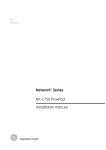
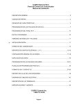
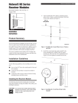
INSTALLATION AND WIRING
To install the card reader, simply wire it into the system. Refer to the following wiring table for details.
GREEN
(DATA)
BLACK
(COM)
RED
(POS)
WHITE
(EGRESS)
BLUE
(OUTPUT)
DESCRIPTION
Connect to the NetworX control panel DATA terminal. This wire is the data-signaling
terminal to all the devices on the buss.
Connect to the NetworX control panel COMMON terminal. Supplies the common side of
the power to the card reader module.
Connect to NetworX control panel AUX POWER + terminal. Supplies power to the card
reader module.
This is an optional EGRESS (exit) input. To use this feature, connect the normally open
egress switch between this terminal and COM. If this feature is not used, there is no need
to connect this wire.
This is an optional open-collector (negative trigger) OUTPUT. It can be used to drive a
relay. To use this feature, connect the coil contacts of a relay between this terminal and
AUX POWER +. Absolute maximum 14 volts @ 25mA.
This is a low current output and must not be used to directly energize high current
door openers.
ENROLLING
The NetworX control panels have the ability to automatically find and store in memory the presence of all keypads,
zone expanders, wireless receivers, output modules, and any other device on the keypad buss. This allows these
devices to be supervised by the control panel. To enroll the devices, enter the Program Mode using the procedure
outlined in the control panel Installation Manual. When the Program Mode is exited, the NX-8 control will
automatically enroll the devices. The enrolling process takes about 12 seconds, during which time the Service LED
will illuminate. User codes will not be accepted during the enrolling process. Once a module is enrolled, if it is not
detected by the control, the Service LED will illuminate.
NX-1701E Installation manual
Page 4
31/01/05
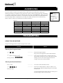
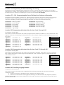
ADDRESSING
Once the reader is wired into the system, the module needs to be addressed. Unlike most
NetworX expanders, the address of any particular reader is determined by itself after installation
is complete. Follow the procedures outlined under the section “PROGRAMMING”. When prompted
to enter the module device number, a card must be scanned at the reader to initiate addressing
(one short beep). When completed (1-2 seconds), the reader will beep back its address (long
beeps). Refer to Table 0-1 that follows for possible addresses.
Table 0-1
Beeps
1
2
3
4
5
6
7
8
Address
113
114
115
116
117
118
119
120
Beeps
9
10
11
12
13
14
15
Scan: To
“present” or
pass a card or
FOB within
sensing range of
the card reader
module.
Address
121
122
123
124
125
126
127
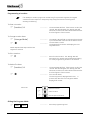
PROGRAMMING
USING THE LED KEYPAD
Only NX-13xx keypad series allow to program user cards.
ACTION
RESULT
Entering the Program Mode
&Á_
& [Go To Program Code]
Factory Default is `^XZ
xxxxxxxx
Enters the Program Mode.
Stay, Chime, Exit, Bypass & Cancel LEDS will flash.
xxxxxxxx
If the "Go To Program Code" is valid, the "Service"
LED will flash and the 5 function LEDs will illuminate
steady. You are now in the Program Mode and
ready to select the module address.
Scan a card.
xxxxxxxx
The card reader will address itself.
& XYW #
xxxxxxxx
Enters the module address. Refer to Table 0-1 on
page 5 for the address assigned by the card reader
module itself.
Entering the Module Address
(example only)
The Armed LED will illuminate while it is waiting for a
programming location to be entered.
NX-1701E Installation manual
Page 5
31/01/05
Programming a Location
If an attempt is made to program an invalid entry for a particular segment, the keypad
sounder will emit a triple error beep (beep, beep, beep), and remain in that segment
awaiting a valid entry.
To Enter a Location:
&
[location] #
xxxxxxxx
The Armed LED will flash. If the location is valid, the
"Armed" LED will extinguish, the "Ready" LED will
illuminate, and the zone LED’s will show the data for
the first segment of this location.
xxxxxxxx
The "Ready" LED will flash to indicate a data change
in process and will continue until the data is saved.
The new data is saved.
The keypad will increment and display the next
segment’s data.
To Change Location Data:
& [changed data]
& À
xxxxxxxx
NOTE: Repeat these steps until the last
segment is reached.
To Exit a Location:
&#
xxxxxxxx
Exits from this location. The “Ready” LED will
extinguish. The "Armed" LED will illuminate waiting
for a new programming location to be entered.
xxxxxxxx
The Armed LED will flash. If the location is valid, the
"Armed" LED will extinguish, the "Ready" LED will
illuminate, and the zone LED’s will show the data for
the first segment of this location.
xxxxxxxx
(Do not enter data.)
To Review The Data:
&
[location] #
&À
The next segment is displayed. Each time is
pressed, the data of the next segment will be
displayed for review.
Shortcuts:
&
&
&
Previous location.
Same location.
Next sequential location.
Exiting the Program Mode:
& EXIT EXIT
NX-1701E Installation manual
xxxxxxxx
Page 6
Exits this programming level.
31/01/05
USING THE LCD KEYPAD
All steps required for programming are the same as the aforementioned LED keypad. The LCD keypad display will
prompt you for the data required. While in the programming mode, and not in a location, the number in parenthesis
is the location you were previously changing. For example, if the display reads "Enter location, then # (5)", it is
reminding you that location 5 was the last location you programmed. In feature selection data, the numbers of the
enabled features will be displayed. The features not enabled will display a hyphen (-).
PROGRAMMING DATA TYPES
Numerical Data
Numerical data can take on values from 0-255 or 0-15 depending on the segment size.
Feature Selection
Feature selection data is used to turn features on or off.
USER CARDS
Adding and de-activating users is done through a combination of entering information at the keypad and scanning
cards. Before a card can be entered, one reader on the system must be programmed with User Card Programming
enabled (Location 242, Segment 1, Option 1, page 11).
It is recommended that only one reader on the system be enabled to modify user cards and
that this reader be located near a keypad. This reader will transfer information to all other
readers in the system once programming is finished.
Once a reader is enabled to modify users, it must be placed into one of the following five modes:
1) Add One User
2) Add Multiple Users w/ Auto-Increment
3) Activate One User
4) De-Activate One User
5) Delete/Reset One User.
Modifying users on a card reader is similar to modifying user codes at a keypad.
MUST BE A MASTER USER IN ORDER TO MODIFY USER CARD INFORMATION.
ACTION
RESULT
&À\
& [master code]
Factory Default is XYZ[
xxxxxxxx
Accesses Code Programming
xxxxxxxx
If the code is valid, the Ready LED will flash.
User Number 2 is used to program user cards, so…
& W Y if the control is an NX-8
& W W Y if the control is an NX-8E
xxxxxxxx
Unit is now ready for you to choose one of the User
Card Programming modes (as if user code 2):
1)
2)
3)
4)
5)
Add One User
Add Multiple Users (w/ Auto-Increment)
Activate Single User
De-activate One User
Delete / Reset One User
IMPORTANT NOTE
Adding or de-activating user cards from a reader will cause the code for User Number 2 to become invalid. Therefore, it
will need to be re-entered after all user cards are programmed into the readers.
NX-1701E Installation manual
Page 7
31/01/05
Adding One User
ACTION
RESULT
& [STAY]
& [3-digit user number]
xxxxxxxx
Accesses Activation mode
xxxxxxxx
If a valid user number is entered, LED1 on any
enabled readers will begin to flash.
Example: X Y [ if 4-digit user code
or W W X Y [ if 6-digit user codes
Scan the card designated for the user
entered in the previous step.
xxxxxxxx
1)
2)
If the user card is not already in the system, it
will be added and mapped to the entered user
number.
If the card is already in the system, the reader
will triple beep and LED1 will continue flashing;
the user number is not incremented in this case.
Adding Multiple Users with Auto-Increment
ACTION
& [CANCEL]
& [3-digit user number]
RESULT
on NX-148E; use [NIGHT] on NX-1248E
xxxxxxxx
Accesses Activation mode
xxxxxxxx
If a valid user number is entered, LED1 on any
enabled readers will begin to flash.
X Y [ if 4-digit user code
or W W X Y [ if 6-digit user codes
Example:
Scan the card designated for the user
entered in the previous step.
xxxxxxxx
Continue scanning user cards until the
desired number of cards has been added.
xxxxxxxx
1)
If the user card is not already in the system, it
will be added and mapped to the entered user
number and LED1 will continue flashing
indicating that the next user card can be
scanned for the next user number.
2) If the card is already in the system, the reader
will triple beep and LED1 will continue flashing;
the user number is not incremented in this case.
After about 30 seconds without a card being
scanned, all the readers in the system will be
updated with the new user card information.
By default, user cards are added and activated. In order to add a user card and
de-activate it at the same time, scan and hold the card to be added until two
beeps are sounded at the reader.
NX-1701E Installation manual
Page 8
31/01/05
Activate One User (Single User)
ACTION
& [CHIME]
& [3-digit user number]
(not available on NX-1248E)
RESULT
xxxxxxxx
xxxxxxxx
Accesses Activation mode
If a valid user number is entered, LED1 on any
enabled readers will begin to flash.
Example: X Y [ if 4-digit user code
or W W X Y [ if 6-digit user codes
Scan any card.
xxxxxxxx
The card information for the user entered in the
previous step will be activated, and LED1 will stop
flashing. After about 30 seconds, all the readers in
the system will be updated.
De-Activate One User
ACTION
& [BYPASS]
& [3-digit user number]
RESULT
xxxxxxxx
xxxxxxxx
Accesses De-activation mode
If a valid user number is entered, LED1 on any
enabled readers will begin to flash.
Example: X Y [ if 4-digit user code
or W W X Y [ if 6-digit user codes
Scan any card
xxxxxxxx
If an individual keeps the
card, it can still be deleted.
Delete / Reset One User
ACTION
& [EXIT]
& [3-digit user number]
The card information for the user entered in the
previous step will be cleared, and LED1 will stop
flashing. After about 30 seconds, all the readers in
the system will be updated.
RESULT
xxxxxxxx
xxxxxxxx
Accesses De-activation mode
If a valid user number is entered, LED1 on any
enabled readers will begin to flash.
Example: X Y [ if 4-digit user code
or W W X Y [ if 6-digit user codes
Scan any card
xxxxxxxx
The card information for the user entered in the
previous step will be cleared, and LED1 will stop
flashing. After about 30 seconds, all the readers in
the system will be updated.
ACTIVATING / DE-ACTIVATING / RESETTING USERS
If User Number 0 is entered, the desired function will be performed on the user
associated with the card scanned.
NX-1701E Installation manual
Page 9
31/01/05
PROGRAMMING LOCATIONS
SCAN METHODS: Legacy mode is default. Alternative mode is shown below in brackets { }.
Refer to Location 242 Segment 1 on page 11, and the Glossary on page 23 for explanation.
Location 0
Programming the Scan Functions
(3 segments of binary data) Location 0 is used to select the particular function(s) that are activated when a card is
scanned. More than one function may be selected. If more than one function is selected, they will execute in order
from function 1 to function 8.
Functions 1-6 will be performed based on the user’s authority as programmed by the [À] [6]
function (refer to keypad user manual).
Segment 1
Single Scan Function {Single Beep}
Program the functions that are performed when a card is scanned {one beep}.
"On" to send Code Entry function to the control panel.
"On" to activate the Armed Away mode.
"On" to activate the Armed Stay mode.
"On" to send the Disarm function to the control panel.
"On" to send Auxiliary Function #1 to the control panel.
"On" to send Auxiliary Function #2 to the control panel.
"On" to broadcast an X-10 function (see Location 241 for programming).
"On" to send a Request To Exit (RTE); and activate the onboard open collector output. (Default
Location 243, Segment 2 must be programmed with a valid zone number for the
is “On”)
RTE to be sent.
LED1 LED2 LED3 LED4 LED5 LED6 LED7 LED8 -
Segment 2
Double Scan Function {Double Beep}
Program the functions that are performed when a card is scanned twice within the 2 Scan Hold Time {two beeps}.
Location 244, Segment 1 programs the length of time between beeps. The descriptions of the options are the same
as for Single Beep Scan Function. Default is 1.
Segment 3
Single Scan Hold Function {Triple Beep}
Program the functions that are performed when a card is scanned and held at the reader for the duration of the 2
Scan Hold Time {three beeps}. Location 244, Segment 1 programs the length of time between beeps. The descriptions
of the options are the same as for Single Beep Scan Function. Default is 1.
Locations 1 - 240
Reserved
Location 241 Programming the X-10 Address for the Scan Functions
(5 segments of numerical data)
Segment 1
Program a number from 0 -15 to represent the corresponding X-10 Module Number from the following table.
Default is 0.
Module
Seg 1
NX-1701E Installation manual
1
0
2
1
3
2
4
3
5
4
6
5
Page 10
7
6
8
7
9 10 11 12 13 14 15 16
8 9 10 11 12 13 14 15
31/01/05
Segment 2
Program a number from 0-15 to represent the corresponding X-10 House code from the following table. Default is 0.
0=A
1=B
2=C
3=D
Segment 3
X-10 ADDRESS CODES
4=E
8=I
5=F
9=J
6=G
10=K
7=H
11=L
12=M
13=N
14=O
15=P
Single Scan Function {Single Beep}
Program the X-10 function that is performed when a card is scanned {one beep}. This location only needs to be
programmed if Location 0, Segment 1, Option 7 is set. Use the following table. Default is 2.
Function #
0
1
2
3
Segment 4
Function performed
All units off
All lights on
On
Off
Function #
4
5
6
All others
Function performed
Dim
Bright
All lights off
Reserved
Double Scan Function {Double Beep}
Program the X-10 function that is performed when a card is scanned twice within the 2 Scan Hold Time {two beeps}.
Location 244, Segment 1 programs the length of time between beeps. The descriptions of the function codes are the
same as for Single Beep Scan Function. This location only needs to be programmed if Location 0, Segment 2, Option 7
is set. Use the above table. Default is 3.
Segment 5
Single Scan Hold Function {Triple Beep}
Program the X-10 function that is performed when a card is scanned and held at the reader for the duration of the 2
Scan Hold Time {three beeps}. Location 244, Segment 1 programs the length of time between beeps. The
descriptions of the function codes are the same as for Single Beep Scan Function. This location only needs to be
programmed if Location 0, Segment 3, Option 7 is set. Use the above table. Default is 2.
Location 242 Programming the Options and Reader Partition
(4 segments of binary data)
Segment 1
System Options:
LED1 LED2 LED3 LED4 LED5 LED6 LED7 LED8 -
"On" if reader is enabled for User Card Programming.
"On" if optical tamper is enabled.
"On" if reader buzzer is to follow typical keypad buzzing. (Default is “On”)
"On" if ding-dong chime enabled (dependent on both Option 3 and chime being enabled).
“On” if an RTE from a scanned card is to be logged as Code Entry. (Default is “On”)
“On” if reader is in NX-1701E Legacy Mode (Default is “On”) Refer to note below.
“On” if an RTE from a zone or the Egress input is to be logged as Code Entry.
"On" if LEDs to extinguish after 2 minutes without a scan (Note: This option doesn't disable the
flashing green LED during card programming.)
The card reader is defaulted to the “Legacy mode”. This mode uses the same scan
method as previous NX-1701E card readers. However, an alternative scan method is available by
turning off LED6 in Location 242, Segment 1. Rather than passing the card (scan) within range of
the card reader, the card can be held at the reader for a specified number of beeps.
Example of Double Scan: Legacy mode -- Pass the card by the reader’s sensor, remove it from the
sensor area, then pass the card by the reader’s sensor once again. Alternative mode -- Hold the
card at the card reader for a total of 2 beeps. Refer also to the Glossary on page 23.
IMPORTANT: If you have older models installed in the system without this enhanced feature, it
could result in two different methods of scanning at various readers.
NX-1701E Installation manual
Page 11
31/01/05
Segment 2
LED1 LED2 LED3 LED4 LED5 LED6 LED7 LED8 -
Segment 3
LED1 LED2 LED3 LED4 LED5 LED6 LED7 LED8 -
Segment 4
LED1 LED2 LED3 LED4 LED5 LED6 LED7 LED8 -
LED1 (Green) Options:
"On" to follow Ready status of system. (Default is “On”)
"On" to toggle with the open collector output activation. (Default is “On”)
"On" if inverted.
Reserved.
Reserved.
Reserved.
Reserved.
Reserved.
LED2 (Red) Options:
"On" to follow Armed status of system. (Default is “On”)
"On" to toggle with the open collector output activation.
"On" if inverted.
Reserved.
Reserved.
Reserved.
Reserved.
Reserved.
Reader Partition:
"On" if reader is in Partition 1.
"On" if reader is in Partition 2.
"On" if reader is in Partition 3.
"On" if reader is in Partition 4.
"On" if reader is in Partition 5.
"On" if reader is in Partition 6.
"On" if reader is in Partition 7.
"On" if reader is in Partition 8.
(Default is “On”)
(Default is “On”)
(Default is “On”)
(Default is “On”)
(Default is “On”)
(Default is “On”)
(Default is “On”)
(Default is “On”)
Location 243 Programming the Zones
(2 segments of numerical data)
Segment 1
Door Shunt Zone
Program the zone that will be monitored as a door for access control. This location must be programmed with a valid
zone for monitored access control functions to work properly. (Default is 0)
Additionally, this zone must be configured in the control panel as an “access control” zone by
programming an unused Zone Type Characteristic in locations 111-169 (Seg 4, Opt 4).
Segment 2
Request To Exit (RTE) Zone
Program the zone that will be monitored to signal an RTE. If this segment is programmed with a valid zone and the
zone is faulted, the reader will activate its onboard open collector output and send the RTE. (Default is 0)
Additionally, this zone must be configured in the control panel as an RTE zone by programming an unused
Zone Type Characteristic in locations 111-169 (Seg 4, Opt 3).
NX-1701E Installation manual
Page 12
31/01/05
Location 244 Programming the Various Reader Timers
(4 segment of numerical data)
Segment 1
Scan Time
Enter the amount of time required to hold a card between beeps to activate the functions programmed in Location 0,
Segments 2 and 3. This timer is timed in 1/100-second increments from 0 to 2.55 seconds. (Default is 100 = 1 second).
Segment 2
Relay Active Time
Enter the amount of time the onboard open collector output is energized once activated. This timer is timed in 1second increments from 0 to 255 seconds. (Default is 10 = 10 seconds).
Segment 3
Door Fault Warning Time
Enter the amount of time a monitored zone (see Location 243, Segment 1) must be faulted before sounding a warning
(local buzzer). The door fault warning is timed in 1-second increments from 0 to 255 seconds. (Default is 30 = 30
seconds).
Segment 4
Door Fault Alarm Time
Enter the amount of time a monitored zone (see Location 243, Segment 1) must be faulted before sending an alarm
condition to the control panel. The door fault alarm is timed in 1-second increments from 0 to 255 seconds. (Default is
0 = 0 seconds).
Location 245 Resetting the Reader Address
(1 segment of numerical data) If it is necessary to reset the address of the reader, enter a 0 in this location.
This will cause the reader to cease functioning. If a card is scanned with the system in Program
Mode, the reader will again find an available address and set itself, beeping back to the user the
address that was found as per the table on page 5. If the system is not in Program Mode and a card is
scanned at a reader with a reset address, then it will sound an error beep.
Location 246 Programming the Access Options
(2 segments of binary data)
Segment 1
LED1 LED2 LED3 LED4 LED5 LED6 LED7 LED8 -
Segment 2
LED1 LED2 LED3 LED4 LED5 LED6 LED7 LED8 -
Door Options
"On" if locking mechanism is a Maglock or Drop Bolt.
"On" if access is allowed regardless of Armed status of the system.
"On" if the door is not to be latched unlocked during an open schedule.
"On" if onboard open collector output only triggers during an open schedule.
“On” if onboard open collector output only triggers during a close schedule.
“On” if Forced Entry Alarm is logged.
“On” if access allowed without an RTE.
"On" if relay operates normally during off-schedule (outside of regular operating hours)
Enabling the Schedules for the Onboard Open Collector Output:
"On" if driver follows Schedule 1.
"On" if driver follows Schedule 2.
"On" if driver follows Schedule 3.
"On" if driver follows Schedule 4.
"On" if driver follows Schedule 5.
"On" if driver follows Schedule 6.
"On" if driver follows Schedule 7.
"On" if driver follows Schedule 8.
NX-1701E Installation manual
Page 13
31/01/05
Segment 3
LED1 LED2 LED3 LED4 LED5 LED6 LED7 LED8 -
More Door Options:
"On" if egress input is to be disabled.
Reserved
Reserved
Reserved
Reserved
Reserved
Reserved
Reserved
Location 247 Programming the Opening Time for Schedule 1
(2 segments of numerical data)
Segment 1
Segment 2
Program the hour of the opening time in 24-hour format. (Default is 8 = 8:00 AM)
Program the minutes after the hour of the opening time for Schedule 1. (Default is 0)
Location 248 Programming the Closing Time for Schedule 1
(2 segments of numerical data)
Segment 1
Program the hour of the closing time in 24-hour format. (Default is 20 = 8:00 PM)
Segment 2
Program the minutes after the hour of the closing time for Schedule 1. (Default is 0)
Location 249 Programming the Days for Schedule 1
(1 segment of binary data)
LED1 =
LED2 =
LED3 =
LED4 =
LED5 =
LED6 =
LED7 =
LED8 =
"On" if schedule is active on Sunday.
"On" if schedule is active on Monday.
"On" if schedule is active on Tuesday.
"On" if schedule is active on Wednesday.
“On” if schedule is active on Thursday.
“On” if schedule is active on Friday.
“On” if schedule is active on Saturday.
“On” if schedule is disabled on holidays.
Locations 250 - 270 Programming the Schedules 2 - 8
Locations 250 - 270 are used to program the opening times, closing times, and days for Schedules 2 - 8. Each
schedule has three locations that are programmed with the same steps as Schedule 1 described previously. Refer to
Schedule 1 (Locations 247 - 249 above) for specific instructions.
Location 250 – Opening Time for Schedule 2
Location 251 – Closing Time for Schedule 2
Location 252 – Days for Schedule 2
Location 253 – Opening Time for Schedule 3
Location 254 – Closing Time for Schedule 3
Location 255 – Days for Schedule 3
Location 256 – Opening Time for Schedule 4
Location 257 – Closing Time for Schedule 4
Location 258 – Days for Schedule 4
Location 259 – Opening Time for Schedule 5
Location 260 – Closing Time for Schedule 5
Location 261 – Days for Schedule 5
NX-1701E Installation manual
Page 14
Location 262 – Opening Time for Schedule 6
Location 263 – Closing Time for Schedule 6
Location 264 – Days for Schedule 6
Location 265 – Opening Time for Schedule 7
Location 266 – Closing Time for Schedule 7
Location 267 – Days for Schedule 7
Location 268 – Opening Time for Schedule 8
Location 269 – Closing Time for Schedule 8
Location 270 – Days for Schedule 8
31/01/05
Location 271 Programming the Date of Holidays in January
(8 segments of numerical data) Program the day of the month in January that the Opening time in a schedule is
suppressed. For example, if the opening should not occur on January 1, program a “1” in Segment 1. This feature can
be repeated up to a maximum of 8 holidays per location (month). (Default is No holidays)
Locations 272 – 282 Programming the Date of Holidays from February to December
(8 segments of numerical data) Locations 272 - 282 are used to program the day of each month, from February to
December, in which the Opening time in a schedule is suppressed. Each location will accommodate up to a
maximum of 8 holidays, and programmed with the same steps as Location 271 described previously.
Location 272 – February holidays
Location 273 – March holidays
Location 274 – April holidays
Location 275 – May holidays
Location 276 – June holidays
Location 277 – July holidays
Location 278 – August holidays
Location 279 – September holidays
Location 280 – October holidays
Location 281 – November holidays
Location 282 – December holidays
Location 283 Programming Activation Data for User Cards 1 through 120
(15 segments of binary data)
This location is used to select which user cards 1 through 120 are activated. If the LED is “on”, the card is active. Each
segment has 8 LEDs corresponding to the 8 possible user cards. Example: Segment 4, LED 2 indicates that user card
26 is active.
Segment 1
Segment 2
Segment 3
Segment 4
Segment 5
Segment 6
Segment 7
Segment 8
User Cards 1 - 8
User Cards 9 - 16
User Cards 17 - 24
User Cards 25 - 32
User Cards 33 - 40
User Cards 41 - 48
User Cards 49 - 56
User Cards 57 - 64
Segment 9
Segment 10
Segment 11
Segment 12
Segment 13
Segment 14
Segment 15
User Cards 65 - 72
User Cards 73 - 80
User Cards 81 - 88
User Cards 89 - 96
User Cards 97 - 104
User Cards 105 - 112
User Cards 113 - 120
LED1 = Card 1
LED2 = Card 2
LED3 = Card 3
LED4 = Card 4
LED5 = Card 5
LED6 = Card 6
LED7 = Card 7
LED8 = Card 8
Location 284 Programming Activation Data for User Cards 121 through 240
(15 segments of binary data)
This location is used to select which user cards 121 through 240 are activated. If the LED is “on”, the card is active.
Each segment has 8 LEDs corresponding to the 8 possible user cards. Example: Segment 15, LED 8 indicates that
user card 240 is active.
Segment 1
Segment 2
Segment 3
Segment 4
Segment 5
Segment 6
Segment 7
Segment 8
User Cards 121 - 128
User Cards 129 - 136
User Cards 137 - 144
User Cards 145 - 152
User Cards 153 - 160
User Cards 161 - 168
User Cards 169 – 176
User Cards 177 - 184
Segment 9
Segment 10
Segment 11
Segment 12
Segment 13
Segment 14
Segment 15
User Cards 185 - 192
User Cards 193 - 200
User Cards 201 - 208
User Cards 209 - 216
User Cards 217 - 224
User Cards 225 - 232
User Cards 233 - 240
LED1 = Card 1
LED2 = Card 2
LED3 = Card 3
LED4 = Card 4
LED5 = Card 5
LED6 = Card 6
LED7 = Card 7
LED8 = Card 8
Location 285 Code Entry Logging Partition
(1 segment of numerical data)
This location programs the partition that is logged with the Code Entry message and sent when the following
conditions are met:
An RTE scan function is selected (Location 0, Segment 1/2/3, Option 8); and
“RTE from a scanned card is to be logged as Code Entry” is enabled (Location 242, Segment 1, Option 5).
Entering a 0 (zero) will send the lowest valid partition of the reader. Entering 1-16 will send the entered value as the
partition. (Default is 0.)
NX-1701E Installation manual
Page 15
31/01/05
PROGRAMMING WORKSHEETS
LOC
PG
0
10
DESCRIPTION
DEFAULT
YOUR DATA
SCAN FUNCTIONS
Seg 1
SINGLE SCAN FUNCTION (1 Beep)
8
1 = "On" to send Code Entry function to the control panel.
2 = "On" to activate the Armed Away mode.
3 = "On" to activate the Armed Stay mode.
4 = "On" to send the Disarm function to the control panel.
5 = "On" to send Auxiliary Function #1 to the control panel.
6 = "On" to send Auxiliary Function #2 to the control panel.
7 = "On" to broadcast an X-10 function (Loc 241 for programming).
8 = "On" to send an RTE; and activate the onboard open collector output.
Seg 2
DOUBLE SCAN FUNCTION (2 Beep)
1
1 = "On" to send Code Entry function to the control panel.
2 = "On" to activate the Armed Away mode.
3 = "On" to activate the Armed Stay mode.
4 = "On" to send the Disarm function to the control panel.
5 = "On" to send Auxiliary Function #1 to the control panel.
6 = "On" to send Auxiliary Function #2 to the control panel.
7 = "On" to broadcast an X-10 function (Loc 241 for programming).
8 = "On" to send an RTE; and activate the onboard open collector output.
Seg 3
1-240
10
SINGLE SCAN HOLD FUNCTION(3beep)
1
1 = "On" to send Code Entry function to the control panel.
2 = "On" to activate the Armed Away mode.
3 = "On" to activate the Armed Stay mode.
4 = "On" to send the Disarm function to the control panel.
5 = "On" to send Auxiliary Function #1 to the control panel.
6 = "On" to send Auxiliary Function #2 to the control panel.
7 = "On" to broadcast an X-10 function (Loc 241 for programming).
8 = "On" to send an RTE; and activate the onboard open collector output.
RESERVED
241
10
X-10 ADDRESS
Seg 1
MODULE NUMBER
Seg 2
HOUSE CODE
(see chart)
Seg 3
NX-1701E Installation manual
0
X-10 ADDRESS CODES
0=A
4=E
8=I
12=M
1=B
5=F
9=J
13=N
2=C
6=G
10=K
14=O
3=D
7=H
11=L
15=P
SINGLE SCAN FUNCTION (1Beep)
0 = All units off
1 = All lights on
2 = On
3 = Off
4 = Dim
5 = Bright
6 = All lights off
Page 16
0
2
31/01/05
LOC
PG
241
10
242
11
DESCRIPTION
DEFAULT
Seg 4
DOUBLE SCAN FUNCTION (2 Beep)
0 = All units off
1 = All lights on
2 = On
3 = Off
4 = Dim
5 = Bright
6 = All lights off
3
Seg 5
SINGLE SCAN HOLD FUNCTION (3 Beep)
0 = All units off
1 = All lights on
2 = On
3 = Off
4 = Dim
5 = Bright
6 = All lights off
2
YOUR DATA
OPTIONS AND READER PARTITION
Seg 1
SYSTEM OPTIONS
3, 5, 6
1 = "On" if enabled for User Card Programming
2 = "On" if optical tamper enabled
3 = "On" if buzzer follows keypad buzzing
4 = "On" if ding-dong chime enabled (Opt 3 & chime must be enabled)
5 = “On” if an RTE from a scanned card is to be logged as Code Entry
6 = “On” if reader is in NX-1701E Legacy Mode
7 = “On” if an RTE from a zone or the Egress input is to be logged as Code Entry.
8 = “On" if LEDs to extinguish after 2 minutes without a scan
Seg 2
LED1 (GREEN) OPTIONS
1,2
1 = "On" follows system Ready status
2 = "On" to toggle with the Open Collector output
3 = "On" if inverted
4 = Reserved
5 = Reserved
6 = Reserved
7 = Reserved
8 = Reserved
Seg 3
LED2 (RED) OPTIONS
1 = "On" follows system Armed status
2 = "On" to toggle with the Open Collector output
3 = "On" if inverted
4 = Reserved
5 = Reserved
6 = Reserved
7 = Reserved
Reserved
Seg 4
READER PARTITION
1 = "On" if reader is in Partition 1
2 = "On" if reader is in Partition 2
3 = "On" if reader is in Partition 3
4 = "On" if reader is in Partition 4
5 = "On" if reader is in Partition 5
6 = "On" if reader is in Partition 6
7 = "On" if reader is in Partition 7
8 = "On" if reader is in Partition 8
NX-1701E Installation manual
Page 17
1
1,2,3,4,5,6,7,8
31/01/05
LOC
PG
243
12
244
13
245
13
246
13
DESCRIPTION
PROGRAMMING THE ZONES
Seg 1 Door Shunt Zone
Seg 2 Request to Exit (RTE)
Scan Time (1/100 seconds)
100 = 1 second
Seg 2
Relay Active Time (seconds)
10 = 10 seconds
Seg 3
Door Fault Warning Time (seconds)
30 = 30 seconds
Seg 4 Door Fault Alarm Time (seconds)
RESET THE READER ADDRESS
Entering a “0” will reset and cause the reader to
cease functioning.
14
0 = 0 seconds
PROGRAMMING THE ACCESS OPTIONS
Seg 1 DOOR OPTIONS
Seg 3
248
0 = Disabled
0 = Disabled
Seg 1
Seg 2
14
YOUR DATA
READER TIMES
1=
2=
3=
4=
5=
6=
7=
8=
247
DEFAULT
"On" if locking mechanism is a Maglock or Drop Bolt.
"On" if access is allowed regardless of Armed status of the system.
"On" if the door is not to be latched unlocked during an open schedule.
"On" if onboard open collector output only triggers during an open schedule.
“On” if onboard open collector output only triggers during a close schedule.
“On” if Forced Entry Alarm is logged.
“On” if access allowed without an RTE.
"On" if relay operates normally during off-schedule
SCHEDULES FOR ONBOARD OPEN COLLECTOR OUTPUT
1 = "On" if driver follows Schedule 1.
2 = "On" if driver follows Schedule 2.
3 = "On" if driver follows Schedule 3.
4 = "On" if driver follows Schedule 4.
5 = "On" if driver follows Schedule 5.
6 = "On" if driver follows Schedule 6.
7 = "On" if driver follows Schedule 7.
8 = "On" if driver follows Schedule 8.
MORE DOOR OPTIONS
1 = “On" if egress input is to be disabled
2 = Reserved
3 = Reserved
4 = Reserved
5 = Reserved
6 = Reserved
7 = Reserved
8 = Reserved
OPENING TIME FOR SCHEDULE 1
Seg 1 Hour of Opening Time (24-hr format)
Seg 2 Minutes after Hour of Opening
8 = 8 AM
0
CLOSING TIME FOR SCHEDULE 1
Seg 1 Hour of Closing Time (24-hr format)
Seg 2 Minutes after Hour of Closing
20 = 8 PM
0
NX-1701E Installation manual
Page 18
31/01/05
LOC
PG
249
14
DAYS FOR SCHEDULE 1
1 = “On” if schedule is active on Sunday.
2 = “On” if schedule is active on Monday.
3 = “On” if schedule is active on Tuesday.
4 = “On” if schedule is active on Wednesday.
5 = “On” if schedule is active on Thursday.
6 = “On” if schedule is active on Friday.
7 = “On” if schedule is active on Saturday.
8 = “On” if schedule is disabled on holidays.
250
14
OPENING TIME FOR SCHEDULE 2
Seg 1 Hour of Opening Time (24-hr format)
Seg 2 Minutes after Hour of Opening
8 = 8 AM
0
CLOSING TIME FOR SCHEDULE 2
Seg 1 Hour of Closing Time (24-hr format)
Seg 2 Minutes after Hour of Closing
20 = 8 PM
0
251
14
DESCRIPTION
DEFAULT
252
14
DAYS FOR SCHEDULE 2
1 = “On” if schedule is active on Sunday.
2 = “On” if schedule is active on Monday.
3 = “On” if schedule is active on Tuesday.
4 = “On” if schedule is active on Wednesday.
5 = “On” if schedule is active on Thursday.
6 = “On” if schedule is active on Friday.
7 = “On” if schedule is active on Saturday.
8 = “On” if schedule is disabled on holidays.
253
14
OPENING TIME FOR SCHEDULE 3
Seg 1 Hour of Opening Time (24-hr format)
Seg 2 Minutes after Hour of Opening
8 = 8 AM
0
CLOSING TIME FOR SCHEDULE 3
Seg 1 Hour of Closing Time (24-hr format)
Seg 2 Minutes after Hour of Closing
20 = 8 PM
0
254
14
255
14
DAYS FOR SCHEDULE 3
1 = “On” if schedule is active on Sunday.
2 = “On” if schedule is active on Monday.
3 = “On” if schedule is active on Tuesday.
4 = “On” if schedule is active on Wednesday.
5 = “On” if schedule is active on Thursday.
6 = “On” if schedule is active on Friday.
7 = “On” if schedule is active on Saturday.
8 = “On” if schedule is disabled on holidays.
256
14
OPENING TIME FOR SCHEDULE 4
Seg 1 Hour of Opening Time (24-hr format)
Seg 2 Minutes after Hour of Opening
8 = 8 AM
0
CLOSING TIME FOR SCHEDULE 4
Seg 1 Hour of Closing Time (24-hr format)
Seg 2 Minutes after Hour of Closing
20 = 8 PM
0
257
14
NX-1701E Installation manual
Page 19
YOUR DATA
31/01/05
LOC
PG
258
14
DAYS FOR SCHEDULE 4
1 = “On” if schedule is active on Sunday.
2 = “On” if schedule is active on Monday.
3 = “On” if schedule is active on Tuesday.
4 = “On” if schedule is active on Wednesday.
5 = “On” if schedule is active on Thursday.
6 = “On” if schedule is active on Friday.
7 = “On” if schedule is active on Saturday.
8 = “On” if schedule is disabled on holidays.
259
14
OPENING TIME FOR SCHEDULE 5
Seg 1 Hour of Opening Time (24-hr format)
Seg 2 Minutes after Hour of Opening
8 = 8 AM
0
CLOSING TIME FOR SCHEDULE 5
Seg 1 Hour of Closing Time (24-hr format)
Seg 2 Minutes after Hour of Closing
20 = 8 PM
0
260
14
DESCRIPTION
DEFAULT
261
14
DAYS FOR SCHEDULE 5
1 = “On” if schedule is active on Sunday.
2 = “On” if schedule is active on Monday.
3 = “On” if schedule is active on Tuesday.
4 = “On” if schedule is active on Wednesday.
5 = “On” if schedule is active on Thursday.
6 = “On” if schedule is active on Friday.
7 = “On” if schedule is active on Saturday.
8 = “On” if schedule is disabled on holidays.
262
14
OPENING TIME FOR SCHEDULE 6
Seg 1 Hour of Opening Time (24-hr format)
Seg 2 Minutes after Hour of Opening
8 = 8 AM
0
CLOSING TIME FOR SCHEDULE 6
Seg 1 Hour of Closing Time (24-hr format)
Seg 2 Minutes after Hour of Closing
20 = 8 PM
0
263
14
264
14
DAYS FOR SCHEDULE 6
1 = “On” if schedule is active on Sunday.
2 = “On” if schedule is active on Monday.
3 = “On” if schedule is active on Tuesday.
4 = “On” if schedule is active on Wednesday.
5 = “On” if schedule is active on Thursday.
6 = “On” if schedule is active on Friday.
7 = “On” if schedule is active on Saturday.
8 = “On” if schedule is disabled on holidays.
265
14
OPENING TIME FOR SCHEDULE 7
Seg 1 Hour of Opening Time (24-hr format)
Seg 2 Minutes after Hour of Opening
8 = 8 AM
0
CLOSING TIME FOR SCHEDULE 7
Seg 1 Hour of Closing Time (24-hr format)
Seg 2 Minutes after Hour of Closing
20 = 8 PM
0
266
14
NX-1701E Installation manual
Page 20
YOUR DATA
31/01/05
LOC
PG
267
14
DAYS FOR SCHEDULE 7
1 = “On” if schedule is active on Sunday.
2 = “On” if schedule is active on Monday.
3 = “On” if schedule is active on Tuesday.
4 = “On” if schedule is active on Wednesday.
5 = “On” if schedule is active on Thursday.
6 = “On” if schedule is active on Friday.
7 = “On” if schedule is active on Saturday.
8 = “On” if schedule is disabled on holidays.
268
14
OPENING TIME FOR SCHEDULE 8
Seg 1 Hour of Opening Time (24-hr format)
Seg 2 Minutes after Hour of Opening
8 = 8 AM
0
CLOSING TIME FOR SCHEDULE 8
Seg 1 Hour of Closing Time (24-hr format)
Seg 2 Minutes after Hour of Closing
20 = 8 PM
0
269
14
270
14
271
272
273
274
275
276
277
278
279
280
281
282
15
15
15
15
15
15
15
15
15
15
15
15
283
15
DESCRIPTION
DAYS FOR SCHEDULE 8
1 = “On” if schedule is active on Sunday.
2 = “On” if schedule is active on Monday.
3 = “On” if schedule is active on Tuesday.
4 = “On” if schedule is active on Wednesday.
5 = “On” if schedule is active on Thursday.
6 = “On” if schedule is active on Friday.
7 = “On” if schedule is active on Saturday.
8 = “On” if schedule is disabled on holidays.
HOLIDAYS IN JANUARY (8 max)
HOLIDAYS IN FEBRUARY (8 max)
HOLIDAYS IN MARCH (8 max)
HOLIDAYS IN APRIL (8 max)
HOLIDAYS IN MAY (8 max)
HOLIDAYS IN JUNE (8 max)
HOLIDAYS IN JULY (8 max)
HOLIDAYS IN AUGUST (8 max)
HOLIDAYS IN SEPTEMBER (8 max)
HOLIDAYS IN OCTOBER (8 max)
HOLIDAYS IN NOVEMBER (8 max)
HOLIDAYS IN DECEMBER (8 max)
ACTIVATION DATA FOR USER CARDS 1 - 120
1 = User Cards 1 – 8
2 = User Cards 9 – 16
3 = User Cards 17 – 24
4 = User Cards 25 – 32
5 = User Cards 33 – 40
6 = User Cards 41 – 48
7 = User Cards 49 – 56
8 = User Cards 57 – 64
9 = User Cards 65 – 72
10 = User Cards 73 – 80
11 = User Cards 81 – 88
12 = User Cards 89 – 96
13 = User Cards 97 – 104
14 = User Cards 105 – 112
15 = User Cards 113 – 120
NX-1701E Installation manual
Page 21
DEFAULT
No holidays
No holidays
No holidays
No holidays
No holidays
No holidays
No holidays
No holidays
No holidays
No holidays
No holidays
No holidays
YOUR DATA
_
_
_
_
_
_
_
_
_
_
_
_
_
_
_
_
_
_
_
_
_
_
_
_
_
_
_
_
_
_
_
_
_
_
_
_
_
_
_
_
_
_
_
_
_
_
_
_
_
_
_
_
_
_
_
_
_
_
_
_
_
_
_
_
_
_
_
_
_
_
_
_
_
_
_
_
_
_
_
_
_
_
_
_
LED1 = Card 1
LED2 = Card 2
LED3 = Card 3
LED4 = Card 4
LED5 = Card 5
LED6 = Card 6
LED7 = Card 7
LED8 = Card 8
31/01/05
_
_
_
_
_
_
_
_
_
_
_
_
LOC
PG
284
15
285
15
DESCRIPTION
ACTIVATION DATA FOR USER CARDS 121 - 240
1=
User Cards 121 – 128
2=
User Cards 129 – 136
3=
User Cards 137 – 144
4=
User Cards 145 – 152
5=
User Cards 153 – 160
6=
User Cards 161 – 168
7=
User Cards 169 – 176
8=
User Cards 177 – 184
9=
User Cards 185 – 192
10 =
User Cards 193 – 200
11 =
User Cards 201 – 208
12 =
User Cards 209 – 216
13 =
User Cards 217 – 224
14 =
User Cards 225 – 232
15 =
User Cards 233 – 240
CODE ENTRY LOGGING PARTITION
NX-1701E Installation manual
Page 22
DEFAULT
YOUR DATA
LED1 = Card 1
LED2 = Card 2
LED3 = Card 3
LED4 = Card 4
LED5 = Card 5
LED6 = Card 6
LED7 = Card 7
LED8 = Card 8
0
31/01/05
GLOSSARY
TERM
DESCRIPTION
Alternative Mode…………
Alternative mode is an optional scan method, as opposed to the default
Legacy mode (see below). The card is to be continuously held at the reader
for a specified number of beeps. Example: Hold the card at the card reader’s
sensor for a total of 2 beeps. This is a “double beep” in the alternative mode”.
This method becomes available when Location 272, Segment 1, Option 6 is
disabled.
Double Beep……………….
An audible indicator (beep, beep).
Double Beep Scan………..
When a user card is scanned and held at the reader for 2 beeps, the reader
will perform the functions as programmed in Location 241, Segment 4.
Legacy Mode………………
Legacy mode is used to describe the default operation of the card reader’s
scanning method. This mode uses the same scan methods as prior versions
of the card reader modules. Example: Pass a user card by the reader’s sensor,
remove it from the field, then pass the card by the reader’s sensor once again
during the time programmed in Location 244, Segment 1. This is a “double
scan” in the legacy mode.
Request To Exit (RTE)……
A zone can be programmed to monitor an open door. The RTE activates the
onboard open collector output and sends a message on the buss.
Scan……………………….
To “present” or pass a card or FOB within sensing range of the card reader
module.
Single Beep………………..
An audible indicator (beep).
Single Beep Scan…………
When a user card is scanned and held at the reader for 1 beep, the reader will
perform the functions as programmed in Location 241, Segment 3.
Triple Beep………………...
An audible indicator (beep, beep, beep).
Triple Beep Scan………….
When a user card is scanned and held at the reader for 3 beeps, the reader
will perform the functions as programmed in Location 241, Segment 5.
NX-1701E Installation manual
Page 23
31/01/05
SPECIFICATIONS
DIMENSIONS
Approx. 38mm W x 114mm L x 25mm D with 150mm cable
OPERATING POWER
12 VDC, Supplied by panel or NX-320E
CURRENT DRAW
40mA Standby with Green LED
110mA Maximum
OPERATING TEMPERATURE
-31 to +151 degrees F
-35 to +66 degrees C
NX-1701E Installation manual
Page 24
31/01/05
DECLARATION OF CONFORMITY
SECURITY LIFESAFETY COMMUNICATIONS
MANUFACTURERS DECLARATION OF
CONFORMITY
For
Product identification:
Model/type
Category (description)
Brand
: NX-1701E
: Smart card reader
: GE-InterlogiX/Caddx
BOM revision level
: 11 June 2003, 5157D
Manufacturer:
GE Interlogix PTY, LTD.
646 Whitehorse Road
Mitcham 3132
Australia
EU Representative:
GE Interlogix B.V.
Kelvinstraat 7
6003 DH Weert
The Netherlands
Concerning
RTTE
EMC
Safety
Underwriters Laboratories Inc.
Radio
GE-ILX CE_qualification_plan: CEQP_NXCS-1700
Report: NC4364-081403
BP9453-A2
Project No: 03CA26086
EN50130-4(1995)
EN60950(2000)
+A1(1998)
IEC60950(1999), 3 rd Ed.
Report: NC4364-081403
Project No: 03CA26086
EN300330-2 v1.1.1 (06-2001)
A sample of the product
has been tested by:
Test report reference
Applied standards
Equipment class identifier (RF products falling under the scope of R&TTE)
Not Applicable
None (class 1 product)
X
(class 2 product)
Means of conformity
We declare under our sole responsibility that this product is in conformity with Directive 93/68/EEC (Marking) and/or
complies to the essential requirements and all other relevant provisions of the 1999/5/EC (R&TTE) based on test
results using harmonized standards in accordance with the Directives mentioned.
NX-1701E Installation manual
Page 25
31/01/05
X
X
X
X
X
Approved in / Permis en / Toegestaan in / Permesso in
Austria
X
Iceland
X
Norway
Belgium
X
Ireland
X
Portugal
Denmark
X
Italy
X
Spain
Finland
Liechtenstein
X
Sweden
France
X
Luxembourg
Switzerland
Germany
X
Netherlands
X
United Kingdom
Greece
www.gesecurity.com
EMEA Distribution is a division of GE Security EMEA bvba
COPYRIGHT ©2005
© GE Security EMEA bvba. All rights reserved. GE Security EMEA bvba grants the right to reprint this manual for
internal use only. GE Security EMEA bvba reserves the right to change information without notice.