1
NX-KNX (Cod. NXKNX)
Konnex interface for NetworX panels
Installation Manual
DT02038HE1011R01
GENERAL DESCRIPTION
The NX-KNX gateway is a completely fanless embedded controller without moving parts which can connect
a NetworX NX-V2 or NX-8E panel to a domotic system based on a Konnex protocol. This gateway
bidirectionally translates the statuses of the intrusion detection panels connected to it into Konnex events
and also translates Konnex events into default actions for the intrusion detection panels.
The gateway can be connected to the intrusion detection panels of the NetworX family in the following way:
- NX-V2 connected to an NX-584 domestic automation module which is, in turn, connected to the
gateway via the serial port
- NX-V2 connected to an NX-590 network module which is, in turn, connected to the gateway via the
Ethernet socket gate
- NX-8E directly connected to the gateway via the serial port using the NXP003 adaptor
- NX-8E connected to an NX-590 network module which is, in turn, connected to the gateway via the
Ethernet socket port
This Gateway is also able to stream Galileo series DVR videos on the web server.
With a user password, you can also use the gateway to operate the NetworX panels using the web browser
controls and view the Galileo DVR video streams.
PACKAGE CONTENT
The package contains the following:
> NX-KNX WEB CONTROLLER
> 220V AC power cord
> KNX bus connector
> Ethernet network cable
> Manual
TECHNICAL CHARACTERISTICS
The main hardware characteristics of the product are outlined in the table below:
Dimensions
155 x 155 x 25mm
Ports and Connections
RS232 (DB9)
USB (2x)
Ethernet Network (2x)
KNX Interface
Power Supply
7V - 18V DC
220V AC Transformer supplied
Absorption
Max 6W
Operating Temperature
0°C - 50°C
2
NX-KNX ELECTRICAL CONNECTIONS
To use the NX-KNX WEB CONTROLLER, you must have the following connections:
> Power supply using the transformer supplied
> KNX bus using the specific connector supplied (with the possibility of making "enter-exit" connections)
> Main data network on a LAN port for connecting secondary NetworX panels and for Galileo series DVRs.
> COM line for connecting to the main NetworX panel with the DB9 serial cable and the following PIN
configuration:
NX-584
NX-KNX
1
1
2
3
3
2
4
6
5
5
6
4
8
8
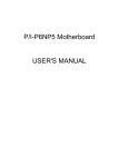
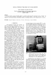
Connection to the KNX bus must respect the polarities indicated in the figure below:
3
PRELIMINARY CHECKS
Before accessing the NX-KNX pages, it is a good idea to ensure that the following requirements have been
met:
> A PC/MAC with Ethernet network card (you must have Administrator rights to configure the Internet
connection) and one of the following web browsers:
- Mozilla Firefox (*)
- Apple Safari
- Google Chrome
- Microsoft Internet Explorer
(*) We advise using Mozilla Firefox for configuration
> To configure KNX management, you will need ETS Professional software installed on your computer and
the ETC design for the domotic system with which you want to interact
NX-584 AND NX-590 MODULE INSTALLATION
The installation of NX-584 and NX-590 modules is described in the manuals of the specific modules
themselves.
The programming procedures for these modules is provided below to simplify the installation process.
NX-584 PROGRAMMING
Location 0 - Programming the option indicators
Option 1 off = Binary.
Location 1 - Frequency transmission table
Segment 1: set to value 4 to have a transmission speed of 9600 baud.
Location 2 - Activating variation send
Segment 1:
1 OFF
2 ON
3-4 Reserved
5 ON
6 ON
7 ON
8 ON
Segment 2:
1 ON
2 ON
3 ON
4 ON
5-8 Reserved
4
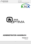
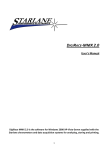
Programming locations 0-2 in DL900 is as illustrated below:
Location 3 - Programming command/request activation
Segment 1:
1 Reserved
2 ON
3 Reserved
4 ON
5 ON
6 ON
7 ON
8 ON
Segment 2:
1 ON
2 ON
3 ON
4 ON
5 ON
6-8 Reserved
Segment 3:
1 ON
2 ON
3 ON
4 ON
5 ON
6 ON
7 ON
8 ON
Segment 4:
1 Reserved
2 Reserved
3 ON
4 ON
5 ON
6 ON
7 ON
8 ON
Location 4 - Programming the LCD keypad address
Enter the address of the keypad from where you would like the information to be collected.
Enter the value 192
5
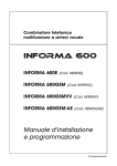
Programming locations 3-4 in DL900 is as illustrated below:
NX-590 PROGRAMMING
Location 0
5 ON
Programming location 0 in DL900 is as illustrated below:
6
Location 87
Enter the IP address of the NX-KNX gateway
Location 88
Enter the user port of the Ethernet socket you want to use to connect to the NX-KNX gateway
Programming locations 58 and 88 in DL900 is as illustrated below:
Location 89
Segment 1:
1 Reserved
2 ON
3 Reserved
4 Reserved
5 ON
6 ON
7 ON
8 ON
Segment 2:
1 ON
2 ON
3 ON
4 ON
5 Reserved
6 Reserved
7 Reserved
8 Reserved
7
Programming location 89 in DL900 is as illustrated below:
Location 90
Segment 1:
1 Reserved
2 ON
3 Reserved
4 ON
5 ON
6 ON
7 ON
8 ON
Segment 2:
1 ON
2 ON
3 ON
4 ON
5 ON
6 Reserved
7 Reserved
8 Reserved
Segment 3:
1 ON
2 ON
3 ON
4 ON
5 ON
6 ON
7 ON
8 ON
8
Segment 4:
1 Reserved
2 Reserved
3 ON
4 ON
5 ON
6 ON
7 ON
8 ON
Location 91
Enter the address 192 of the keypad that contains the labels
Programming locations 90 and 91 in DL900 is as illustrated below:
PROGRAMMING THE NX-8E PANEL
To connect the NX-8E panel to the NX-KNX gateway, you will need to use the NXP003 adaptor that can be bought
separately from the panel so that the serial output presents as a classic COM 9 PIN connector.
If you want to create it yourself, the pinouts are outlined below:
IDC 2x5 PIN Connector
The red cable
on PIN 1
COM DB9 male Connection Table
1
6
2
7
3
8
4
9
5 10
PIN DB9
3 TX
8 CTS
2 RX
7 RTS
5 GND
PIN IDC
3
4
5
6
9
9
9
5
6
1
Instructions for programming the panel for serial connection to the NX-KNX gateway are provided below:
Location 207
Programme the value 1.
Location 208
Programme the value 2 to set the speed at 9600 Baud.
Location 209
Leave this location in OFF state
Location 210
Segment 1:
1 Reserved
2 ON
3 Reserved
4 Reserved
5 ON
6 ON
7 ON
8 ON
Segment 2:
1 ON
2 ON
3 ON
4 ON
5 Reserved
6 Reserved
7 Reserved
8 Reserved
Programming locations 207, 208, 209 and 210 in DL900 is as illustrated below:
10
Location 211
Segment 1:
1 Reserved
2 ON
3 Reserved
4 ON
5 ON
6 ON
7 ON
8 ON
Segment 2:
1 ON
2 ON
3 ON
4 ON
5 ON
6 Reserved
7 Reserved
8 Reserved
Segment 3:
1 ON
2 ON
3 ON
4 ON
5 ON
6 ON
7 ON
8 ON
Segment 4:
1 Reserved
2 Reserved
3 ON
4 ON
5 ON
6 ON
7 ON
8 ON
Location 212
Insert the keypad address: 192
Programming locations 211 and 212 in DL900 is as illustrated below:
11
ACCESS TO NX-KNX GATEWAY
To configure the NX-KNX gateway, you will first need to connect your computer to the network with the controller. The
gateway can connect in two ways:
> Connecting NX-KNX with the LAN network to which the computer is already connected
> Directly connecting NX-KNX to your computer using a "CROSS-OVER" network cable
In both cases, you will need to configure (even if only temporarily) your computer's network so that you can dialogue with
the NX-KNX gateway, whose default address is:
192.168.0.110
To do this, depending on your operating system if the factory address is not compatible with your network, proceed in the
following way:
> Manually set your computer's IP address using the first three numbers of the NX-KNX address and assigning a value
of between 1 and 254 to the fourth number (ensuring that it is not already in use) and not using 110. E.g.
192.168.0.100
> If required, specify "255.255.255.0" as a network mask
Once you have modified your network configuration, ensure that you are correctly communicating with the NX-KNX
gateway by opening the "COMMAND PROMPT" window (in Windows; for other operating systems please see the
relevant manuals) and enter the command:
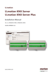
ping 168.0.110
12
ensuring that the communication has been made correctly, as in the figure below:
If the ping command receives a positive response (as in the example), open a web browser (recommended MOZILLA,
not recommended INTERNET EXPLORER) and enter the following address:
http://192.168.0.110
You will then get connected to the following webpage:
where you will need to enter "admin" as the login and "admin" as the password.
There is also a user password that will not let you edit the Konnex programming or the gateway configuration: "user" as
the login and "user" as the password.
13
14
SYSTEM OVERVIEW
The NX-KNX web pages are a fixed structure where it is possible to identify some elements that are always present in all sections of
the software. With reference to the figure below, please note:
15
1
.
NAVIGATOR
This shows you the position of the current page within the hierarchical structure of the system at any moment. By clicking on its
items, you can quickly return to previously visited sections.
> MAIN MENU
This contains all the options required to change the default page view and for quick access to the main sections of the software
and also has a quick search for objects in the database
> SIDE PANEL
If open, this contains additional information for browsing or configuring the objects within the surveillance project. It can also be
used as a fast project browser using the "tree" function
> BOTTOM PANEL
If open, this allows you to view alarm messages generated by the system or to plan regular checks on objects. It can also contain
an on-screen keypad to assist in using the touchscreen
> SCROLL ARROWS
These allow you to move around within the page if the content exceeds the view boundary of your browser
The main menu contains the following icons:
REFRESH PAGE
This refreshes your current page (the same as the "refresh" function in your browser)
CHANGE CURRENT VIEW
With these buttons you can choose the view (list, icons) for the current page
list
icons
HOME
This takes you back to the default surveillance page
ADMINISTRATION
This allows you to access the administration menu
CHANGE USER
This logs you out of the system and the window for entering your access information appears once again
SAVE ON FLASH
This prompts you to save the configuration permanently on the disc before turning off the system
QUICK SEARCH
This allows you to search for one or more objects within the database
NOTE: not all icons are visible on all pages of the software. Users without Administrator rights may only view some
icons as some operations are not permitted for end users
16
The side panel contains the following icons:
DETAILS
Default page of the side panel. You can see additional page information, such as the object category selector
(where present)
TREE
This allows you to browse quickly through the surveillance page structure
The bottom panel contains the following icons:
ON-SCREEN KEYPAD
This brings up an on-screen keypad to enter touchscreen text without a physical keyboard
MESSAGES
This allows you to see a list of messages and notifications generated by the system
In the pages that have an object list, there is a toolbar at the beginning of the list that contains the buttons relating to possible actions
to be performed in the page. Some actions are available without selecting any object, while others require you to select at least one
object (by checking the selection box in the first column).
The buttons available are:
BACK
This allows you to return to the previous page (the same as the "back" button on your browser)
NEW
This allows you to create new objects, as described in more detail below
UPDATE
This allows you to save the changes made on one or more objects in the list
EDIT
This allows you to access the detailed profile of an object to edit its properties
REGROUP
This allows you to put the selected objects into a folder
REMOVE
This allows you to remove the selected objects from the current folder
DELETE
This permanently deletes the selected objects from the database
CREATE EVENT
This allows you to associate an on-screen or email notification with the selected objects (described in more detail
below)
17
GATEWAY NX-KNX SETUP
Push “Administration” button
to have the following page :
Select “Networx NX” icon:
We need to setup the user code Konnex will use to send request and commands to panel.
To do so press “Modify defined panel”:
18
Fill in the code konnex will use to request and command the panel then press “Save”:
Remember to setup an user with the same code on the panel.
19
Push “Click here” to re-start services and so apply modfifiations.
Setup the first area going back to the previous menù
and selecting “New NX partition”
Fill in name and description of the partition:
Press ”Save”.
20
If you press “Click here” to re-start services.
Go on with the partition setup adding all partitions used and managed in konnex.
Setup now NetworX zones pushing “New NX zone”:
Fill in name and description of the zone:
Go on with the setup of the next zones.
Now you can save setup pressing
to save modification to flash.
21
Now it is important to re-start services:
To do so press “Click here”.
Now we should setup konnex addresses. To do so go to main menu and select “Manage NX partitions”
Now you have along list of states. Press arrow ( > ) you will find out where knonnex address are
located
The first one is a command konnex address to let other konnex items to send commands to panel. The second one is a
status address to let other konnex items to read the status of the panel.
To fill in or modify konnex address, simply write it on the filed in the x/y/z format where x and y are between 1 and 15, z
is between 1 and 255:
Then you will see that the button
pushing button
will change its color. Now you are able to update your new configuration
.
Make sure to restart services.
22
Now you can move to setup konnex addresses for zones selecting “NX zones KNX management”:
The first one is a command konnex address to let other konnex items to send commands to panel. The second one is a
status address to let other konnex items to read the status of the panel.
To fill in or modify konnex address, simply write it on the filed in the x/y/z format where x and y are between 1 and 15, z
is between 1 and 255:
Then you will see that the button
pushing button
will change its color. Now you are able to update your new configuration
.
Make sure to restart services.
23
Now you can move to setup konnex addresses for panel selecting “Panel warnings KNX management”:
The first one is a command konnex address to let other konnex items to send commands to panel. The second one is a
status address to let other konnex items to read the status of the panel.
To fill in or modify konnex address, simply write it on the filed in the x/y/z format where x and y are between 1 and 15, z
is between 1 and 255:
Then you will see that the button
pushing button
will change its color. Now you are able to update your new configuration
.
Make sure to restart services.
NX-KNX ADMINISTRATION MENU
The administration menu allows you to configure and customise every aspect of NX-KNX. The pages of this menu are
structured in a table of icons and each icon allows you to call up a sub-menu or a specific function.
The number and type of the icons available in the administration menu depends on the user who has logged into NXKNX. Users with Administrator rights can access all the items in the menu, but the "power managers" and "basic users"
can only use a limited number of icons in accordance with the access rules of the respective user groups. To edit these
rules, please see the section in this manual regarding user management.
SYSTEM CONFIGURATION
This section allows you to set the main parameters of the controller. This contains the following items:
> NETWORK CONFIGURATION
This allows you to set the NX-KNX addresses and network card functions
> CONFIGURE DATE AND TIME
This allows you to configure the date and time of the system and the time update criteria online and on the KNX bus
> MODULE AND LICENCE MANAGEMENT
This allows you to enter or update the licences that belong to the various modules that make up the system and configure the
main operating parameters (e.g.: communication ports)
> USERS AND USER GROUPS
This allows you to manage the system access accounts and their associated rights
24
NETWORK CONFIGURATION
This page allows you to edit the NX-KNX network card parameters. You can independently configure the two network ports (identified
as "LAN" and "WAN" respectively - see the connection diagrams) by entering the respective configuration parameters into the specific
text boxes as illustrated in the figure on the side.
The LAN port cannot be deactivated and is considered the main port for access to NX-KNX. It can only be configured by entering a
static IP address. The WAN port can be activated by selecting the specific box and can be activated in both DHCP mode (automatic
address allocation) and by manually entering the IP address. Please note that in all cases the WAN port must be connected to subnetwork that is different from the LAN port and must, therefore, be configured with a different address allocation class, otherwise the
NX-KNX will not work.
If you would like to use both network ports under the same sub-network, you can activate the "Network Bridge" (by selecting the
specific box). In this case, you must enter the IP address, the network mask and the default gateway that will be adopted by both
ports, in "HUB" mode.
It is also possible to manually enter the addresses of the DNS servers used by NX-KNX for access to the Internet. In addition to these
(by selecting the appropriate box) you can also select the automatic DNS address allocation from the DHCP server so that the WAN
port is activated in DHCP mode.
Once the network settings have been modified, click on the save button to implement them. NX-KNX will restart with the new network
parameters. Please remember that BRIDGE mode requires a slightly longer set up time than the other configurations.
Remember to nat ports 80 and 443 to connect to gateway from WAN
If access to NX-KNX is anticipated via Internet, you need to ensure that the "default gateway" address corresponds to the router that
provides public access (e.g. ADSL router). If it does not, you will not be able to reach the controller from outside the local network.
DATE/TIME MANAGEMENT
You can set the system clock in the configuration page with the same name (on the side). The clock can also be updated via Internet.
To do this, you will need to specify the time server and the minute intervals of the update (enter a value from 1 to 50).
Finally, this page allows you to plan any communication service restart at a given time on one or more days per week to be used for a
particular system load to regularly free up the system resources.
MODULE AND LICENCE MANAGEMENT
With this screen, you can manage the configuration, update and registration of system modules. The software is provided with some
pre-installed modules and you can extend their function with optional additional modules. For each module you can update and
register the user licence and, again through this page, you can set the main operating parameters. For more information, please see
the specific documentation in this manual or in the manuals of the additional modules.
USER AND USER GROUP MANAGEMENT
This section allows you to consult the list of users and user groups configured in the system and create new ones. For a detailed
description on user management, please see the specific section in this manual.
To modify pre defined admin and user passwords please logon to gateway and connect to the following links
for ADMIN: http://IP ADDRESS/smartdomuspad/modules/system/externalframe.php?url=../system/editobject.php?id=15
for USER: http://IP ADDRESS/smartdomuspad/modules/system/externalframe.php?url=../system/editobject.php?id=17
modifying IP ADDRESS with the real IP address of the gateway
DATABASE MANAGEMENT
This page allows you to perform operations in the database that contains the NX-KNX configuration. In particular, you can:
> EXPORT THE CURRENT DATABASE
If you choose to export the current configuration, when you press the "finish" button you will be asked to save the file containing
the system configuration on your client computer (or on the NX-KNX if you are operating locally).
> IMPORT A BACKUP
By selecting the item "import new database", you will be given the possibility to choose a previously exported file. When you click
on the "finish" button, the current configuration will be replaced with the configuration contained in the file itself.
> RESTORE FACTORY SETTINGS
This option allows you to restore factory settings on the NX-KNX.
Note: this operation does not change the IP address assigned to the network card.
25
SOFTWARE UPDATE
This page allows you to install updates or additional modules on your NX-KNX that were not installed at the time of purchase.
To update software, first make a backup of the configuration and then follow the guided instructions by uploading the file containing
the update (without decompressing it on your computer) and ensuring that the update has completed correctly in the summary page. If
no error messages flash up (in red), click on the "add file" button to prepare the package for update. Once the page has reloaded,
click on "update" to start the update procedure. Wait for confirmation that the operation has been completed without performing any
other action or closing the browser (these actions might cause the device to malfunction). Then restart if necessary.
NOTE: this operation could take up to half an hour depending on the size of the update package.
EMPTY AND REFRESH CACHE
This command empties all the temporary files generated by NX-KNX during use in order to speed up browsing. These files - called
"caches" - can in some cases lead to a view that is not updated and not consistent with the configuration in the database, especially if
it is accessed contemporarily by different workstations and different users.
NOTE: emptying the cache can cause a view error if you load a NX-KNX page at the same time as another workstation. If this
happens, reload the page using the specific browser command.
SAVE DATA ON DISC
During normal functioning, NX-KNX uses a dynamic copy of its database held in the RAM memory (volatile) to minimise access times
to data and the number of scripts on the flash memory. When you change the project configuration, the data does not get immediately
transferred onto the flash memory (permanent). Instead a procedure is activated that saves the data permanently within the next 5
minutes. Any data to be written permanently onto the flash memory is highlighted by an icon in the main menu that turns red when the
RAM memory configuration is not aligned with the disc.
If you need to save data permanently to the disc immediately (such as to switch of NX-KNX), you can click on this icon which will
immediately save all the data permanently.
COMMUNICATION SERVICES MANAGEMENT
This section allows you to interact with the system by performing one of the operations reported below. In normal circumstances, you
do not need to intervene in these, but in some cases it might be useful to force a restart or reload of communication services (on which
NX-KNX is based) or of the entire controller operating system.
> RESTART COMMUNICATION SERVICES
This operation restarts services based on NX-KNX functioning. This operation is not usually necessary (or it is requested after
operations that require it) but it can be a good idea in some cases to restart the application
> SHUT DOWN THE SYSTEM
This shuts down the Linux operating system on which NX-KNX is based (note: this operation does not require the controller to shut
down the system electrically)
> RESTART THE SYSTEM
This restarts the controller's operating system
DIAGNOSTICS
The diagnostics page allows you to see a summary of the machine configuration to identify any inconsistencies or configuration errrors
that might compromise correct functioning.
LOG
This page allows you to consult the system log that can contain error messages or notifications sent to the user that have been
collected during device operation.
26
OPTIONS
This section allows you to set some parameters that determine the device's actions:
> SYSTEM
> EMAIL
This allows you to set the connection parameters to a SMTP server to send messages:
> TVCC
This allows you to specify in pixels the width and height of the video stream viewed
> DYNDNS
This allows you to configure the DYNDNS client integrated in the device. This requires a valid account on www.dyndns.org.
The page also shows the outcome of the last update operation on the DYNDNS server.
ADVANCED COMMUNICATION WITH THE NETWORX PANEL
When installed for the first time, NX-KNX already has a preconfigured NETWORX panel in its database. To configure the parameters
for this panel:
> Access the administration menu and select the item "NetworX NX"
> Select the item "Change default NX panel"
> Change the name assigned to the panel (to better identify it) and the optional description given to it
> Type of communication: specify if NX-KNX has to connect to the panel via serial connection or via Internet
> Based on this choice, specify which port to use for the connection (in the event of serial/USB connection) or IP address and
network port
> Enter the authentication code to use for connection to the panel. The code must be valid to access the panel. This code is used
by NX-KNX for operations that do not require users to enter codes
> Save the changes and restart the communication service as prompted by the message that will appear on the screen
NOTE: when the panel is saved for the first time, picture icons are created that will allow you to view and manage the status and/or
alarm signals of the panel. Once you have saved, you can see these objects in the "panel status" section on the bottom in the panel
card.
CONFIGURING MORE THAN ONE PANEL
You can configure NX-KNX to dialogue with more than one panel, on different serial/USB ports or via Internet.
To do this, click on the item "new NX panel" in the "NetworX NX" section of the administration menu and enter the same
information as above. In creating areas and zones, you will be able to specify which panels they should refer to.
27
CREATING NEW AREAS
To configure one or more areas to monitor in NX-KNX, please follow the procedure below:
> Access the homepage (by pressing "home" in the main menu)
> Select the item "NX Areas"
> In the panel at the start of the list, select the item "create a new object" and then indicate the number of areas to create and
choose "NetworX NX - Area". You also have the option to specify whether the new objects need to be created in the current folder
or in another folder (see further down for creating folders)
> Click on "create" and wait for a few seconds.
Once the page has reloaded, the new objects will appear. The software automatically numbers the new objects progressively from
number 1.
NOTE: if there are no further configuration operations to be performed, follow the instructions given in the bottom panel to restart the
communication services and set up NETWORX-NX KNX WEB CONTROLLER for correct communication. If there are further
configuration operations, ignore the message and continue with configuration, only restarting after you have completed the last
operation. This indication applies to any operation that requires you to restart services.
By clicking on the icon in the last column on the right, you will see a side panel - normally closed, but you can view it by clicking the
open/close arrow at the top right - containing all the functions of the area that can be managed. The status of the icons is aligned with
the panel in real time.
28
Some of the icons in the panel can be controlled. If you click on one of them, a virtual keypad will pop up where you can
enter the activation code by selecting the corresponding numeric keys or by directly entering with the keypad. This code
is the same as the code used for real keypad operations. If the code is correct, the function will be enabled and the icon
will change status after a few seconds. If it does not become enabled, the icon will return to its original status and you
will see an error message.
EDIT AREA PROPERTIES
You can edit the name assigned to an area by simply entering the new name in the corresponding text box. You can also edit the icon
associated with that area by clicking on it and selecting an icon - among those available in the library - from the side panel. Once you
have made the changes and after checking that the selection box (first column of the list) corresponding to the modified areas is
highlighted (blue), click on "update" on the panel to implement the changes. After a few seconds the page will reload.
To edit other properties of an area, select the area with its selection box (first column) and then select "edit" from the panel. You will
see the detailed profile where you can also specify - in addition to the name, the description and icon - to which panel ("communication
section") it belongs if you are configuring more than one panel. In addition, this profile also shows the folders in which the area is
located (see below) and the functions available for that area with regard to the panel.
CREATING AND EDITING A ZONE
In the same way as the areas, you can create new zones by accessing the specific page from the homepage ("Zone NX") and
selecting "new", then specifying how many objects to create, ensuring that you specify "Networx NX - zone" as the type of object to
create. In this case, again, the system will automatically number the new zones progressively starting from the last zone found in the
database or from 1 if this is a new configuration.
By clicking on the icon of a zone in the "actions" column, you will see a list of the statuses as provided by the panel in real time. When
this is on the screen, you cannot perform interactive actions.
Similarly to areas, you can edit zone names directly on the list and detail all the properties by accessing the relative
profile and proceeding in the same way as described for areas.
CREATING A NEW FOLDER
NX-KNX allows you to monitor areas and zones of the Networx NX panels by organising them into folders and sub-folders in an
absolutely arbitrary way. Usually, through these folders, the end user can "navigate" within environments in which the building is
structured.
To do this, there is an "environment" item on the system homepage. When you access this folder you can create sub-folders by
clicking on "new" on the panel and indicating how many folders to create, ensuring that you specify "folder" as the type of object.
In the same way as for areas and zones, you can create as many sub-folders as you want in the current folder. You can edit the name
and the icon of each of the sub-folders by entering the new name and selecting a new icon from the library, then confirming it by
pressing "update". You can detail the properties of a folder by accessing its profile:
> Name: label associated with the folder
> Description: optional field where you can enter a comment
> Image: picture icon associated with the folder (selected from the library available in the side panel)
> default view: you can decide whether the folder content is shown in list or icon form as shown in the figure on the side.
Alternatively, you can choose the "popup" view which will show the folder content in a side panel when the corresponding icon is
chosen
29
NOTE: The Administrator can temporarily change the view of a folder from list to icons using the corresponding buttons available in
the main menu. Base users cannot change this view as they are restricted to the default view established by the person configuring
the system.
PUTTING OBJECTS INTO FOLDERS
You can put various types of objects into folders, starting with other folders to create a type of "hierarchical tree" for navigation.
30
The areas or zones created previously can be put into one or more folders. To do this, all you need to do is access the page "NX
areas" or "NX zones" respectively, select the areas/zones of interest and click on the "regroup" button on the panel. Then select the
destination folder and confirm with the "run" button.
NOTE: a copy IS NOT made when an object if put into a folder, unlike the file of a disc. Instead, a "relationship" is created in the
database between the object and the folder. You can then always remove the association between the object and folder by pressing
"remove" on the panel without this action deleting the object which you can then take out of other folders it is in
Operations on objects can also be performed by the search engine which can be accessed by using the specific box on the top right of
the main menu. All you need to do is enter one or more keywords to obtain a list of all the objects that respond to those keywords, on
which you can perform operations such as edit, regroup, delete etc...
The search engine also lets you recover the sub-objects associated with the area and zone functions that are usually available in the
side panel and insert them under "free objects" within folders to allow the user to access single functions directly.
31
NETWORX PANEL MANAGEMENT VIA KONNEX
INTRODUCTION
NX-KNX also allows you to manage the functions of the panel, the areas and zones available on the web interface
through telegrams that are sent or received on a KNX domotic bus.
Before attempting the configuration described in this chapter, you will need to create a domotic project using ETS
software, creating a series of group addresses that will communicate with the device. These addresses must be entered
manually in NX-KNX as described in the sections below.
KNX COMMUNICATION CONFIGURATION
Before starting to configure the rules of bidirectional communication with the domotic system, it is a good idea to ensure
that KNX communication is correct. To do this, go to the administration menu, select "KNX" and then "configure KNX
communication". If you use the integrated KNX port, you must have "internal interface" selected and the device must be
set to "/dev/ttyS1". If you want to use an IP/KNX gateway, select the corresponding type and enter the parameters as
set in the ETS software.
MANAGE NX AREAS VIA KNX
The individual functions associated with every area defined in NX-KNX can be associated with one or more KNX group
addresses based on the specific properties of each of them. To do this, access the page "KNX management NX areas"
and identify the functions of the area in question in the list. Alternatively, search for the relevant objects using the search
engine, specifying "Networx NX - Area Function" as the object type.
Once you have identified the object that you want to manage with KNX, click on the arrow in the "details" column to open
the relative box below the corresponding line. In this box, you can enter the address of the KNX group (in "3 level"
format, i.e. "0/0/1") on which you will receive the status change signal and - for objects that can be controlled - an
address (different to the status) through which you can command the corresponding function from the KNX bus.
NOTE: although the system allows it, we strongly advise against using the same group address for different functions on
different objects and on different operations - status change and transmission - performed on the same object. Only use
this type of configuration in special cases and carefully ensure that the gateway functions correctly.
32
Once you have inserted the addresses for all the functions (ensuring not to change page in the meantime), save the
changes by pressing the "update" button in the panel at the start of the list. Follow the same procedure for any additional
objects and then restart the communication service to implement the changes.
MANAGE NX ZONES VIA KNX
In a similar way, you can associate the status transmission of the NX zones on the KNX bus by identifying the
corresponding functions in the "KNX management NX zones" page and by inserting the KNX address in the detail box of
where you want to transmit the status, or by using the search engine.
MANAGE NX PANEL STATUSES VIA KNX
In a similar way, you can associate the status transmission of the NX zones on the KNX bus by identifying the
corresponding functions in the "KNX management panel statuses" page and by inserting the KNX address in the detail
box of where you want to transmit the status, or by using the search engine.
TEST THE KNX GATEWAY
Once you have configured the bidirectional exchange rules between the Networx NX and the KNX system, all you need
to do is edit the panel status to start the corresponding telegrams sending on the KNX bus and, viceversa, to start
sending ON/OFF commands from the KNX bus on the command addresses to pilot the intrusion detection system.
We suggest you use the ETS bus monitor to ensure that the gateway functions correctly in all operating conditions and to
simulate telegram transmission.
33
NOTIFICATIONS
NX-KNX allows you send messages to the user when a status change of objects relating to the Networx NX occurs.
You can configure two types of notifications:
> SCREEN NOTIFICATIONS: messages viewed on the web pages of the system that inform the user of an anomaly with the
date/time of the event
> EMAIL NOTIFICATIONS: emails sent to one or more recipients when an event occurs
NOTIFICATION CONFIGURATION
You can associate notifications with all the objects for "zone function", "area function" and "panel status" which can be found in the
sections "KNX management NX zones", "KNX management NX areas" and "KNX management panel statuses" respectively (or by
using the search engine as seen above).
Select one or more objects from the list with which you would like to associate a notification, then click on "create new event" in the
toolbar. A page will appear where you can choose which action to perform at the status change of the selected objects. In the "create
new object" section, select the type of notification to create. If more than one object is selected, choose "yes" in the "create multiple
object" item to create a notification associated with each of the panel objects. Click on "new" to continue.
On the next page, for each of the objects selected, you will be asked which status must trigger a notification. Choose the desired
status in the drop-down menu, then confirm to implement the changes. If you leave "at every change of value", the notification will be
sent every time the object of reference changes value. On the contrary, by choosing a specific status among those provided, only this
event will trigger the notification.
34
EMAIL PARAMETER CONFIGURATION
To correctly send emails, NX-KNX must be connected to the Internet and suitably configured with the SMTP server parameters it is
supported on. Enter the required information in the email options page in the "maintenance" section of the administration menu as
illustrated above.
INTRODUCTION
NX-KNX allows you to monitor video streams by one or more GALILEO DVR videos.
GALILEO CHANNEL CONFIGURATION
To configure a new channel (video camera) of a GALILEO DVR, go to the administration menu, select the item "video surveillance"
and click on "new Galileo channel". Alternatively, from the list of objects of the folder in which you would like to insert the new video
channel, select "new" from the toolbar and specify "TVCC - Galileo channel" as the type.
In the tab that pops up, enter the following properties:
> Name: label associated with video signal
> Description: optional field where you can insert a comment
> Image: icon associated with the video camera
> Channel: specify the video camera channel number in the DVR Galileo
> IP Address: DVR network address
> Port: network port on which the DVR provides the video signal (default: 80)
> Protocol: communication protocol with the DVR (default: HTTP)
> Width and height: pixel size of the video signal when viewed in the web page
> Resolution: video stream resolution requested to the DVR (insert a valid resolution for the specific DVR)
> Video format: choose "JPEG motion" to view the images with the DVR native format, "photogram stream" to regularly request the
last photogram from the DVR (for slow connections)
> Activate PTZ: this allows you to activate coordination of the video camera dome movement. If activated, this allows you to specify
the parameters for coordinating camera movement and zoom.
35
Once you have created the object, by clicking on the relative icon, a page will appear in which you can view the DVR
video stream in real time.
KONNEX CONNECTION PARAMETERS
On “Administration menu” we have two icons: “Configuration konnex comunicazione" which contains gateway
parameters. Icon "Export ETS configurstion" allow to export gateway setup on a PC which has got an ETS application.
Declaration of Conformity:
HESA S.p.A. Via Triboniano, 25 - 20156 MILAN declares that the NX-KNX equipment conforms to the essential requisites required
by CE norms:
- 2004/108/CEE
The following regulatory documents were applied:
EN55022:2006 Class A
EN50130-4:1995+A2:2003
EN61000-3-2:2006
EN61000-3-3:1995+A1:2001+A2:2005
DT02038HE1011R01
36