Transcript
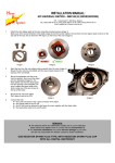
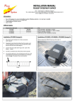
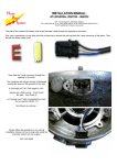
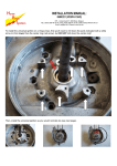
INSTALLATION MANUAL:
HPI UNIVERSAL DIGITAL BATTERY IGNITION: 12V OSCILLATOR DC/AC
HPI – Kuilenstraat 97, 3960 Bree, Belgium
TEL: (0032) 089-46 74 39 | FAX: (0032) 089-47 33 28 | GSM: (0032) 0495-53 90 21
Email: [email protected] | Website: www.hpi.be
This manual explains how the CDI-unit, wiring loom, rotor, pick-up and ht-coil should be installed on the engine.
Follow all these steps to ensure the correct functioning of the CDI-unit.
Installing the CDI-unit
Fix the CDI-unit to the frame. Connections:
Black
Red
Ground
Power
Black (with ring)
Orange
Ground
HT-coil
Red/white
White/blue
Black/white
Pick-up
Pick-up
Kill switch
Yellow (optional)
Curve switch
Green (optional)
Powerjet
Connect cable to the ground of the bike.
Connect cable throught the on/off switch to the 12V of the battery.
Always use this switch to turn off the engine!
Attach the HT-coil (together with this cable) to the frame for mass.
Connect cable to the HT-coil. To minimize electrical interference, try to keep this cable clear of
other cables, and fasten it near to the frame.
Connect this 2-pole connector to the pick-up sensor.
Connect to kill switch on bike. Needs to be switched to the ground to kill the ignition.
This doesn’t power down the CDI-unit, so it shouldn’t be used to turn off the engine,
ALWAYS use the on/off switch (power switch) to turn off the engine!
Connect this cable to a switch (on/off like) which connects to the ground. When this cable (through
the switch) is disconnected from the ground, curve 1 is selected. When connected (through the
switch) to the ground, curve 2 is selected)
Connect this to the powerjet. Will switch to ground at programmed values. (optional)
Fasten all the cables to the frame and keep them clear of hot places.
Please keep in mind the following items:
the CDI-unit must not be exposed to mechanical stress
the CDI-unit must not be exposed to excessive heat (not behind the radiator, close to the cylinder or the exhaust)
the CDI-unit must not be exposed to electrical interferences (not close to the ht-coil)
the CDI-unit must not be directly exposed to fluids (water, gasoline, oil,…)
Place the CDI-unit so the wiring loom from the pick-up can reach the CDI-units wiring loom.
Don’t extend or shorten the cables.
Installing the rotor and the pick-up
The rotor needs to be placed on an axis which rotates at the same RPM as the engine. The pick-up needs to be placed at a distance of
0,5mm to 0,6mm from the tooth of the rotor. In this case there is a reliable signal transmitted to the CDI. Fix the pick-up to the engine
block. Now put the engine in it’s OT (remove spark plug and use a micrometer to make a correct measurement). Now place the rotor
on the axis and position as it’s shown on this drawing. Note that the end of the tooth is still 2mm from the center of the pick-up.
Tighten the rotor to the axis in this position.
left rotating
right rotating
Programming the CDI-unit
All our digital CDI units are programmable using the TuneBox software and a USB interface. Whit this powerful software tool you are
able to design your own ignition curves to obtain maximum performance of your engine. You can freely download TuneBox from our
website www.hpi.be.
To avoid damaging your CDI and engine, stop the engine and switch off the power to the CDI during programming of the unit.
ATTENTION: Use resistor spark plug type, with resistor spark plug cap!