1
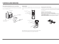
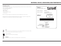
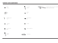
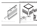
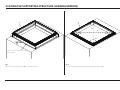
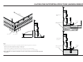
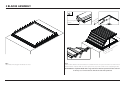
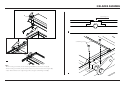
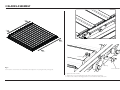
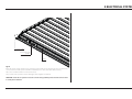
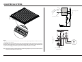
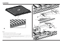
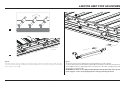
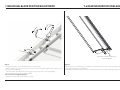
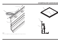
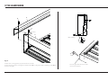
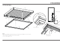
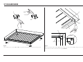
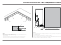
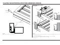
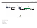
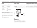
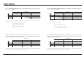
Helyos Liberty Installation manual 05150ING REV 0032014 INSTALLATION MANUAL Dear Installer This manual contains advice for a rapid and precise installation of the various components. Although we are sure that you know how to use our products we still recommend that you read our indications carefully. We always welcome any suggestions or indications on possible improvements to the installation techniques or the layout of the manual. We would also remind you that during installation you should always use materials that are in full respect of the environment. It is also good practice to release, in addition to the declaration of conformity as required by law, a final declaration of correct installation according to the specifications in the manual. HELYOS LIBERTY is a CORRADI S.p.A. product. All technical interventions necessary for the installation must be carried out by authorised and specialised technicians. All unauthorised interventions (tampering, technical modification etc.) during the warranty period will invalidate said warranty. CORRADI S.p.A. reserves the right to make technical modifications to the components or products, except for the main features, at any time and without prior notice. 0032014 INDEX Symbols Controls and versions Material check, unpacking and preparation Screws and hardware 1 Pre-assembling the supporting structure 2 Laying the supporting structure (leaning version) 3 Blades assembly 4 Electrical system 5 Motor 6 Limit stop adjustment 7 Individual blade position adjustment 7a Rain infiltration on blades 8 Inserting drip guard brushes 9 Tin hardware 10 Laying the supporting structure (embedded version) Electrical system Electrical system: motor wiring diagram Data sheets Example CORRADI SPA INSTALLATION MANUAL HELYOS LIBERTY 4 6 7 8 9 10 12 15 18 19 20 20 21 22 25 27 28 30 31 3 of 32 SYMBOLS SYMBOLS The symbols indicated are used to draw the attention of the installer to arguments of particular importancefor the safety of persons, the product or to indicate particular operating conditions In the case of any incompatibility, contact CORRADI S.p.A. GENERAL SAFETY WARNINGS Destination of use Any improper use of HELYOS LIBERTY relieves CORRADI S.p.A. of all liability. When using the canvas it is good practice to remember that all moving parts can be a source of danger. Attention: general operating note Do not remove any casings after the installation and, if they are removed for maintenance, make sure that before removal the power supply is cut off (in case of motorised movement). Attention: greater attention to what you are reading Attention: general hazard; possible risk of damage to persons, property, components It is recommended never to intervene on moving parts and to ensure that no operator is near to the awning before reactivating it after a technical or maintenance intervention. Attention: risk of electrical hazard It is compulsory to cut off the power supply (if present) when carrying out an installation, maintenance, repair or adjustment intervention. Attention: risk of crushing hands It is recommended that a caution sign be placed on the power supply master switch with the following indications: “Attention! Do not touch. Service personnel at work”. Contact: CORRADI S.p.A. or the authorised retailer GENERAL PRECAUTION Before undertaking any assembly, maintenance or cleaning operations, make sure that you have fully understood the indications in this manual. Failure to respect the regulations contained herein relieves CORRADI S.p.A. of all responsibility for damage caused to persons, animals, property and/or components. The installation personnel must scrupulously respect the local accident prevention regulations in force. All electrical connections for movement, installation of automation accessories etc. must only be made by qualified personnel. If the structure is motorised and installed at a height of less than 250 cm from the ground, the control button must be of the ‘dead-man’ type and the opening and closing operations must be clearly visible. 4 of 32 PRECAUTIONS AND WARNINGS The maintenance and installation personnel (installers, electricians etc.) must have sufficient expertise and psychophysical and attitudinal requirements for undertaking the tasks at hand. Always check the correct mounting and working efficiency of the electrical and manual drives during the assembly. In case of anomalies, immediately stop the work and contact the service department of CORRADI S.p.A. CORRADI SPA INSTALLATION MANUAL HELYOS LIBERTY 0032014 SYMBOLS The use of non-original spare parts, or unauthorised interventions or modifications shall relieve CORRADI S.p.A. of any responsibility for damage caused to persons, animals or property. It is absolutely forbidden to tamper with the fixings, the supports, the guides, the fixtures, the command and idler units and any other component of the HELYOS LIBERTY. ATTENTION All values indicated are expressed in centimetres (unless otherwise specified). PRELIMINARY CHECKS On receipt of the packed goods and before starting their assembly, check the integrity of the material and the presence of all the components necessary for the installation. Carefully follow the information contained in the “Material check, unpacking and preparation” section. In case of anomalies, immediately contact the authorised retailer or CORRADI S.p.A. 0032014 CORRADI SPA INSTALLATION MANUAL HELYOS LIBERTY 5 of 32 CONTROLS AND VERSIONS WALL MOUNTED CONTROLS (Customer responsibility) To orient the covering blades, press the button in the lower or upper area; on releasing the button (neutral central position), the blades will stop in the required position. RADIO CONTROL If HELYOS LIBERTY is equipped with a radio-controlled motor-drive, use the respective buttons (see figure) to open, close and stop the blades. Opening blades Opening blades Stop Replacing radio control 1 battery This transmitter is powered by a CR2032 type 3 Volt battery. To replace the batteries, open the plate on the back and remove the flat battery, then replace it with a new one, ensuring the polarity is correct. Reposition the plate. Attention: do not invert polarity. Attention: do not use an incorrect battery type. Risk of explosion if the battery is replaced with a model different from that specified. Dispose of the used battery in the appropriate containers. Closing blades Closing blades PRESENT MAN BUTTON (NOT INCLUDED) Opening blades Stop Closing blades The multichannel radio control (15 channels) also enables control of any accessories (optional), such as: lights, side fasteners. 6 of 32 CORRADI SPA INSTALLATION MANUAL HELYOS LIBERTY 0032014 MATERIAL CHECK, UNPACKING AND PREPARATION PRELIMINARY CHECKS The HELYOS LIBERTY is delivered in a strong package that protects it from knocks or scratches. There is a label on the package that indicates: on the package that indicates: t.BOVGBDUVSFSEBUB t0SEFSOVNCFS t/BNFPGBEESFTTFF t$VTUPNFSSFGFSFODFOVNCFS t/¡PGUIFQBSDFM Before opening the package, check that the data corresponds with that in your possession. CORRADI SPA Via Brini, 39 40128 Bologna (ITALIA) tel.051-4188411 - Fax.051-4188400 Cliente / Customer: XXXXXX Indirizzo / Address: XXXXXXXXXXX XXXXXXXXXXXXXXXXX Ordine nr: XXXX/X Collo/Pack 1 di 1 All the elements necessary for mounting the structure, the accessories needed for mounting and the installation, the use and maintenance manual are inside the package. L406396M0010 ETICHETTA PESO Packing list n°: Contenuto/Content: Mark: Rif/Ref: Numero: XXXXXX Comando 0010 FPSERVICE xxxxxxxxxxxxx N.B.: fixing elements such as screws, plugs etc. are not included and must be chosen by the installer based on the type of fixture foreseen (wall, wood, metal etc.). Proceed as follows: - Remove the elements from the packaging. Attention: do not use a knife to avoid the risk of ruining the paint or metal elements. 0032014 CORRADI SPA INSTALLATION MANUAL HELYOS LIBERTY 7 of 32 SCREWS AND HARDWARE Bronze bushing Tcei screw M8 x 40 Plate M8 Washer M8 Self-tapping screw 4 x 25 Notched washer M8 Self-drilling screw Nut M8 Spacer for motor fitting Button screw M8 x 12 TE screw M8 x 50 8 of 32 Syringe silicone RAL colour same as HELYOS LIBERTY RAL (NOT INCLUDED) Motor fitting CORRADI SPA INSTALLATION MANUAL HELYOS LIBERTY 0032014 1 PRE-ASSEMBLING THE SUPPORTING STRUCTURE housing for blade Button screws M8 x 12 A A INSIDE VIEW C C detail of fitting A fig. 1 Insert 2 M8 plates (A) in the supporting profiles with the housings for the blades. 0032014 fig. 2 - Pre-assemble the supporting structure made up of profiles (A) and angle bars (C); - Tighten with the appropriate screws. CORRADI SPA INSTALLATION MANUAL HELYOS LIBERTY 9 of 32 2 LAYING THE SUPPORTING STRUCTURE (LEANING VERSION) A A = 90° = 90° 90° 90° N.B.: Silicone around the perimeter before laying. fig. 3 Position the supporting structure (A) in the installation area. 10 of 32 fig. 4 - Check the right angles and diagonals of the supporting structure (A). CORRADI SPA INSTALLATION MANUAL HELYOS LIBERTY 0032014 2 LAYING THE SUPPORTING STRUCTURE (LEANING VERSION) “X” sid es Fastening on wood Silicone Base not beyond the profile 70 cm. Min. ø5x30 Silicone 70 or 30 cm Fastening on concrete fig. 5 Drill fastening holes in the grooves of profiles (A) of the supporting structure, as follows: - Drill every 70 cm for structures leaning on 4 sides only. - Drill every 30 cm for structures leaning on 2 sides (X). - Drill holes for self-drilling screws D.5 for structures leaning on wooden buildings. - Drill holes suitable for the anchors to be used for structures leaning on concrete buildings. N.B.: In the latter case, mark out the holes on the concrete, move the structure, drill, reposition and fasten. 0032014 CORRADI SPA INSTALLATION MANUAL HELYOS LIBERTY Silicone Base not beyond the profile 11 of 32 3 BLADES ASSEMBLY Lubricating blade bushes RD WA H T n U SO rectio di 116 mm he ly ate in t im rox pp side a on the siti po tre of cen fig. 6 Check that all housings for the blades are clear. 12 of 32 fig. 7 Position all the blades in the same direction so that the front of one is placed over the rear of the next one. Rest the blades complete with accessories (pins, levers, etc.) in the cavities on the supporting beams. ATTENTION: the only blade fitted with a long control lever must be positioned in the central area and in any case no more than 90 cm from the end of the perimeter. CORRADI SPA INSTALLATION MANUAL HELYOS LIBERTY 0032014 3 BLADES ASSEMBLY B “upward” groove 2 self-drilling screws B 1 fig. 8 - While inserting each blade, check that the gaskets B are positioned correctly (1). - While inserting each blade, check that the support is positioned as shown in figure (2). - Fasten all the blades to the supporting profiles using the self-drilling screws (3). 3 0032014 CORRADI SPA INSTALLATION MANUAL HELYOS LIBERTY 13 of 32 3 BLADES ASSEMBLY Nut M8 bushing fig. 9 Connect the control levers of each blade to the adjacent one, using the two joining rods. Screw TCEI M8 x 40 1 - Tighten the first nut M8. 2 - Tighten the second nut M8 against the first, locking them together. 3 - In the event of friction during operation, loosen the first nut by half a turn. 14 of 32 CORRADI SPA INSTALLATION MANUAL HELYOS LIBERTY 0032014 4 ELECTRICAL SYSTEM electric cables connector blocks position 24 V fig. 10 Route the power cables and the motor cable along the profiles of the structure into the area where the connector block and the power unit will be installed (on one of the two sides without levers). Take care to avoid the blade lever movement areas. Carry out the same operations for the LED light cables, if lights are installed. WARNING: all electrical operations must be carried out by qualified professional electricians able to certify the installation. 0032014 CORRADI SPA INSTALLATION MANUAL HELYOS LIBERTY 15 of 32 4 ELECTRICAL SYSTEM Box RE N TE S FA HE supporting profile self-drilling screws e fig. 11 Fasten the connector block and the power unit on the chosen supporting profile, then make the electrical connections inside the box. ATTENTION: the connector blocks house the control unit for the radio control and any connections between cables. Take out the antenna from the wrapping with a small hole and subsequently seal it, then move it slightly outside the protection hood of the structure (not visible). Power supply 12/24 Vac/dc +- N.B.: The motorised drive and the lights kit are both managed by two separate control units, which must be positioned at least 1.5 m apart. 16 of 32 CORRADI SPA INSTALLATION MANUAL HELYOS LIBERTY M CC (NOT SUPPLIED) (NOT OBLIGATORY) 0032014 4 ELECTRICAL SYSTEM electric cable motor fig. 12 Once the correct connections are made: - connect the motor; provisionally power the system and tune the radio control (see instructions on p. 34). - test the radio control is correctly tuned by fully retracting the motor stem and then extending it by approximately one cm. - cut power to the system. 0032014 CORRADI SPA INSTALLATION MANUAL HELYOS LIBERTY 17 of 32 5 MOTOR B Pin D.6 mm. + split pin screw TE M10 x 16 A plates M8 spacer split pin 2 screw TE M8 x 50 1 Button screw M8 x12 A fig. 13 - Position all the blades horizontally (closed) (1). - Constrain the end of the motor stem to the long control lever (2 A). - Translate the M8 plates close to the end of the motor body (2 B). - Constrain the motor using the three M8 plates and the appropriate accessories; do not tighten the three screws fully to enable them to translate along the profile where it is fastened. - Checking again and holding the blades in horizontal position, fasten the motor by tightening the three screws firmly (3A), (3B), (3C). B C 3 18 of 32 CORRADI SPA INSTALLATION MANUAL HELYOS LIBERTY 0032014 6 MOTOR LIMIT STOP ADJUSTMENT A 1 C B More more pressure on blades ure press e ressur Less p 2 fig. 14 Using the remote control, carefully try to move the blades to the two extreme positions: fully open (apQSPY¡GSPNIPSJ[POUBM BOEGVMMZDMPTFEIPSJ[POUBM 1); if the motor strains excessively in the latter phase, adjust as in point (2). 0032014 fig. 15 To vary the contact pressure with blades “closed” (horizontal), proceed as follows: - move the motor piston to intermediate position (A), loosen the three screws that secure the bracket of motor (B) and move it slightly (few mm) in one direction or the other according to the desired adjustment (see indications) (C). ATTENTION: the motor is not equipped with adjustable intermediate limit stops; the entire travel of approx. 15 cm is used, adjusting the two ends by positioning the motor. CORRADI SPA INSTALLATION MANUAL HELYOS LIBERTY 19 of 32 7 INDIVIDUAL BLADE POSITION ADJUSTMENT 7-a RAIN INFILTRATION ON BLADES 3 1 1 3 2 Slot SEAL WITH SILICONE: SMOOTH, DO NOT LEAVE BURRS fig. 16 To adjust the position of the individual blades, proceed as follows: - with the blades semi-closed (5 cm open), loosen the external nuts fastening the blade control levers to the two control profiles (1); - vary the position of the blade using the range given by the slots in the control profiles (2); - finally, tighten the previously loosened nuts (3). N.B.: See notes P.14 (Tightening nuts). Definitively check that the blades operate correctly. 20 of 32 fig. 16-a Following knocks or similar impact, the adherence of the blade caps on the ends of the profile may be compromised, resulting in rain infiltration: to deal with this problem, position the blades vertically and seal the area shown in the figure with silicone. CORRADI SPA INSTALLATION MANUAL HELYOS LIBERTY 0032014 8 INSERTING DRIP GUARD BRUSHES Housing for blade B B A B B A A fig. 17 Insert the brushes (B) into the supporting profiles (A), fitted with housings for the blades. 0032014 CORRADI SPA INSTALLATION MANUAL HELYOS LIBERTY 21 of 32 9 TIN HARDWARE A B B 20 mm. 25 mm. A detail of fitting fig. 18 Drill the four covering profiles as per the dimensions shown. Position the four profiles covering the perimeter sides (A), securing them with self-drilling screws (B) as shown in the figure. 22 of 32 Close the gaps with silicone the same colour as the structure CORRADI SPA INSTALLATION MANUAL HELYOS LIBERTY 0032014 9 TIN HARDWARE GUTTERS (OPTIONAL) B B DETAIL OF FITTING B B C B A A A Splashguard mesh (optional) A A Area to be siliconed A A fig. 19 Attach the gutters (A) to the dedicated housings on the supporting profiles (B) and secure them with the relative self-drilling screws (C) as shown in the adjacent figure. Silicone the gutters (A) at the joins. 0032014 CORRADI SPA INSTALLATION MANUAL HELYOS LIBERTY Splashguard mesh (optional) 23 of 32 9 TIN HARDWARE A A B B A B Detail X A B A B A fig. 20 Silicone all the joins of unions (A) and (B) on the gutters and apply them to the four joining corners. 24 of 32 fig. 21 With a ø10 drill bit, drill the gutters (A) from the inside of the tube of unions (B), creating a series of holes which will act as a filter as indicated in the figure (Detail X). CORRADI SPA INSTALLATION MANUAL HELYOS LIBERTY 0032014 10 LAYING THE SUPPORTING STRUCTURE (EMBEDDED VERSION) A A 60 cm. 60 cm. A 10 cm. A fig. 22 With the special 90x90 mm “L” profile, form a frame on the entire perimeter of the area. Drill the supporting angle bars (A) for fastening: - Drill every 60 cm. - Drill holes for self-tapping screws D.8 for structures secured to wooden buildings. - Drill holes for screw anchors M10 for structures secured to concrete buildings. 0032014 B C 17 mm. Layer of silicone before laying the profile (A). fig. 23 Once the perimeter frame is made, place the blades cover over it, repeating the same operations as for the “LEANING VERSION”. Take care to initially position the profiles (A) as shown in the figure. Fasten the supporting structure (A) to the supporting angle bars (B) using self-drilling screws D.6 (C) or through screws M8 and nut M8: drill approximately every 60 cm. CORRADI SPA INSTALLATION MANUAL HELYOS LIBERTY 25 of 32 10 LAYING THE SUPPORTING STRUCTURE (EMBEDDED VERSION) UPPER FINISHING PROFILE (OPTIONAL) B Lower space 45° A B C Upper space Fill with water-repellent foam. B fig. 24 Fill the entire perimeter channel with foam. 26 of 32 fig. 25 To close the upper gap in an embedded installation, use the special profile (B), cutting it to size according to the dimensions of the space. Cut the profiles lengthways module so that the edges are beyond the screws (A). Fasten the finishing profiles (B) with self-drilling screws (C). Seal with silicone. CORRADI SPA INSTALLATION MANUAL HELYOS LIBERTY 0032014 ELECTRICAL SYSTEM 220 V ties power unit 220 > 24 V sealed box receiving control unit for HELYOS LIBERTY motor drive electric cylinder HELYOS LIBERTY motor HELYOS LIBERTY KIT multichannel radio control (15 chan.) (Supplied separately) MOTOR CHARACTERISTICS ELECTRIC CYLINDER: Acme SCREW - Max thrust and tensile stress. = 800 N - Max seal (not powered) = 600 N - Speed: 15 mm/sec - Travel: 150 mm - Protection rating: IP 54 - Power supply: 24 VDC - Intermediate limit stops: none 0032014 CORRADI SPA INSTALLATION MANUAL HELYOS LIBERTY 27 of 32 ELECTRICAL SYSTEM : MOTOR WIRING DIAGRAM 1) TECHNICAL FEATURES (at a temperature of 20°C) - Power supply: from 12 Vdc to 24 Vdc - Dimensions: 44 x 38 x 25 mm 0QFSBUJOHUFNQFSBUVSF GSPNoUP¡$ - Protection rating: IP20 - Type of control: manned - Radio frequency: 433.92 MHz - Transmitters stored: 40 (including radio sensors) - Range (estimated): 100 m in open ground, 20 m inside buildings 2) IMPORTANT NOTES ON RADIO SYSTEMS - Radio systems should not be used in settings with high disturbance factor (for example near police stations, airports, banks, hospitals). A technical inspection is recommended for any radio system to ensure the suitability of the installation site for radio systems. - Radio equipment can be used solely where any disturbance or malfunction of the transmitter or receiver does not constitute a risk factor, or if such risk factor is cancelled out by appropriate safety systems. - Radio systems operating in the same frequency range can interfere with one another, causing malfunctions. 3) ELECTRICAL CONNECTIONS 3.1 POWER SUPPLY The ROLLY EGO DM module can be powered by a minimum of 12 Vdc and a maximum of 24 Vdc. The mains voltage must be applied to terminals 1 and 2. The polarity shown in the wiring diagram (see fig. 1 section A) must be complied with. Failure to comply with the polarity can cause irreparable damage to the module. 3.3 CONNECTING THE MANUAL CONTROL BUTTON (OPTIONAL CONNECTION) The control buttons must be connected to terminals 3 and 5, the wire shared by the buttons must be connected to terminal 4 (see fig. 1 section A). The control buttons must be “momentary action” switches; do not use toggle switches. More control buttons can be connected to the module through a parallel connection. To apply an ascent or descent control, hold down the relative button for at least 0.5 sec, release the button to lock the manoeuvre. e Power supply 12/24 Vac/ dc ATTENTION The installation and initial setup procedures are the responsibility of a specialised technical installer. +M CC fig. 1 3.2 MOTOR CONNECTION The motor winding operations must be connected to terminals 7 and 8 (see fig. 1 section A). A single direct current motor must be connected for each module. Check that the motor rating plate data are compatible with the module (see section 2 “Technical features”) and that the power source is able to provide levels of voltage and current compatible with the module and the motor. 28 of 32 CORRADI SPA INSTALLATION MANUAL HELYOS LIBERTY 0032014 ELECTRICAL SYSTEM : MOTOR WIRING DIAGRAM 4) FIRST INSTALLATION As soon as it is powered, the module checks it has the code of at least one transmitter in the memory. If at least one transmitter is in the memory, the module begins operating normally. If the memory is blank, the module commands 4 brief motor movements and enters “transmitter programming” mode, so that a valid code from a portable transmitter can be programmed. To enter the first transmitter in the memory: - if the 4 movements of the motor were in ascent, press the “ASCENT” key on the transmitter to be stored. - if the 4 movements of the motor were in descent, press the “DESCENT” key on the transmitter to be stored. NOTE: If 8 sec after the end of the 4 brief movements the module has still not received the valid ASCENT or DESCENT radio command, the module quits programming and the motor can only be operated using the control buttons. 5) RESTORING FACTORY SETTINGS (RESET) 1) Cut power to the module. 2) Connect terminals 3, 4 and 5 together (see fig. 2 section A). 3) Power the module. After approximately 30 sec the motor makes two brief movements (one opposing the other) to signal factory settings have been restored. 4) Cut power to the module. 5) Restore the connections. 6) Power the module. Follow the instructions given in the section e 6) IMPORTANT NOTE ON RADIO SYSTEMS - It is not advisable to use radio systems in areas with strong interference (e.g. near police stations, airports, banks, hospitals, ports, Wi-Fi systems, etc.). A technical inspection is required prior to installing any radio system to identify any sources of interference. - Radio systems can be used where any disturbance or malfunction of the transmitter or receiver does not constitute a risk factor, or if such risk factor is cancelled out by appropriate safety systems. - The presence of radio devices operating at the same transmission frequency (433.92 MHz) can interfere with the radio receiver inside the motor, reducing system capacity and limiting system operability. N.B.: For more in-depth information, see the “INSTRUCTION LEAFLET” provided with the “Rolly” control unit. +- NOTE: for more detailed instructions, see the documentation provided with the Rolly Ego control unit. M CC fig. 2 Salita Discesa 0032014 N.B.: Corradi reserves the right to make periodic innovations in order to improve the installation and use of its products: to that end, should electrical components different from those shown be supplied, please refer to the corresponding manuals provided separately. Stop Prog CORRADI SPA INSTALLATION MANUAL HELYOS LIBERTY 29 of 32 DATA SHEETS TAB.1 - HELYOS WIND RESISTANCE CLASS - Maximum dimensions and wind resistance class* as per BEAUFORT TAB.2 - HELYOS LIBERTY WIND RESISTANCE CLASS - Maximum dimensions and wind resistance class* as per BEAUFORT width [cm] 300 350 400 305 cl. 8 cl. 7 cl. 6 362 cl. 7 cl. 7 cl. 6 400 cl. 6 cl. 6 cl. 6 514 cl. 5 *the class is valid for both single modules and a combination of several modules on the projection and width sides up to a maximum of 4 modules projection (cm) projection (cm) width [cm] 300 350 400 305 cl. 11 cl. 10 cl. 9 362 cl. 11 cl. 10 cl. 9 400 cl. 11 cl. 10 cl. 9 514 cl. 11 cl. 10 cl. 9 610 cl. 11 cl. 10 cl. 9 *the class is valid for single modules CLASS 5 = 70 N/m2 = 38 Km/h CLASS 6 = 110 N/m2 = 49 Km/h CLASS 7 = 175 N/m2 = 60 Km/h CLASS 8 = 270 N/m2 = 75 Km/h CLASS 9 = 365 N/m2 = 87 Km/h CLASS 10 = 502 N/m2 = 100 Km/h CLASS 11 = 660 N/m2 = 117 Km/h TAB.3 - HELYOS WALL FITTINGS FASTENING ANCHORS - Maximum stress* [daN=1Kg] on individual anchor tensile and shear not combined considering 4 bolts per fitting. Values refer to corresponding class indicated in table 1. TAB.4 - HELYOS FEET FASTENING ANCHORS - Maximum stress* [daN=1Kg] on individual anchor tensile and shear not combined considering 2 bolt per foot. Values refer to corresponding class indicated in table 1. width [cm] 300 350 400 305 400 400 400 362 400 400 400 400 400 400 400 514 400 *stresses are valid for both single modules and a combination of several modules on the projection and width sides up to a maximum of 4 modules 30 of 32 projection (cm) projection (cm) width [cm] 300 350 400 305 400 400 400 362 400 400 400 400 400 400 400 514 400 *stresses are valid for both single modules and a combination of several modules on the projection and width sides up to a maximum of 4 modules CORRADI SPA INSTALLATION MANUAL HELYOS LIBERTY 0032014 EXAMPLE - CALCULATION OF WIND RESISTANCE BASED ON THE LOADS AND THE ANCHORS Determination of the anchors Based on the type of wall/floor on which the bolts will be fixed and using the manual of the fixing systems manufacturer to determine which is most suitable. Below we have indicated, purely as an indication, three examples referring to some extracts of HILTI technical sheets which should be consulted for the correct choice and use of the bolts. Tipo di parete/pavimento * Calcestruzzo non fessurato fck, cube = 25 N/mm 2 Mattoneinlaterizio pienoMz12/2.0 DIN105/EN771-1, f b 12 N/mm 2 Tipo di tassell o* Carico raccomandato a trazione ( Nrec) * Carico raccomandato a taglio (V rec) * HSL-3 M8 1110 daN 1780 daN 100 daN 100 daN 100 daN1 90 daN HIT-HY 70 con Profondità posa 80 mm Doppiouni EN 771-1 fb 27 N/mm HIT-HY 70 con HIT-SC 16x... e 2 Profondità posa 80 mm Comparison of loads The recommended load to be used as a comparison is the lowest between the tensile and shear load. The lower between the maximum recommended tensile and shear load must be more than or equal to the maximum load on each anchor taken from the loads data sheet relative to the desired wind speed. Vice-versa, if the recommended load is less than the maximum load on the anchor, evaluate the following options: A) Change type of anchor B) Suitably reinforce the wall or the floor C) Use a loads data sheet for a lower wind speed and assign the consequent wind resistance to the product installed. Attention For the correct choice and use of the bolts refer exclusively to the manual of the fixing system manufacturer * data taken from the HILTI technical sheets (ST_HY 70_2008.PDF page 259-261 and hsl-3.PDF page62-63) 0032014 CORRADI SPA INSTALLATION MANUAL HELYOS LIBERTY 31 of 32 CORRADIGROUP Corradi SpA Corradi System Srl 39, Via G. Brini 40128 Bologna - Italy 18, Via A. Einstein 47122 Forlì - Italy T +39 051 4188 411 F +39 051 4188 400 T +39 0543 796617 F +39 0543 794339 E [email protected] E [email protected] www.corradi.eu


![ManualCover-3Panel10_03 [Converted]](http://vs1.manualzilla.com/store/data/005711777_1-408df82eece155ec198a9b3b174c8b0a-150x150.png)