1
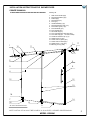
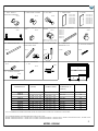
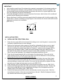
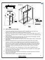
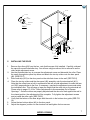
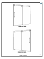
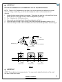
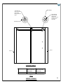
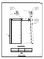
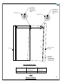
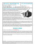
VIGO INDUSTRIES INSTALLATION GUIDE FOR
SHOWER ENCLOSURE (MODEL VG06041)
! SAFETY PRECAUTIONS
This Installation Guide uses the following symbols to indicate important information.
Always observe the instructions indicated by these symbols.
! WARNING
Instructions that, if ignored, could result in death or serious personal injury caused by
incorrect handling or installation of the product. These instructions must be observed for
safe installation.
! CAUTION
The instructions for the following unit is based off of the Vigo brand shower base. The
instructions can not be provided for any other installation other than that of the Vigo brand.
The warranty will be voided if the following was not performed properly.
IMPORTANT
Maintenance and other important non-personal injury and non-material damage instructions
or statements that should be observed.
It is highly advised to dry fit the unit prior to any installation.
1
INSTALLATION INSTRUCTIONS FOR SHOWER DOOR
OWNER'S MANUAL
PLEASE READ INSTRUCTIONS BEFORE PROCEEDING
1
10
Packing List
1. Wall mount bracket (2pc)
2. Fixed panel holders (2pc)
3. Rollers (4pc)
4. Fixed panel (1pc)
5. Door (1pc)
6. Handle assembly (1pc)
7. Fixed panel bottom clip (1 pc)
8. Door bottom guide (1 pc)
9. Door threshold (1pc)
10. Door stopper (2pc)
11. Structural rail (1pc)
12. Door and fixed panel seal strip (2pc)
13. Door seal strip (3pc., 1 of each is extra)
14. Threshold extension clip (1 pc)
15. Phillips screw 2" (2pc)
16. Plastic anchors green (4pc)
17. Plastic anchors white (2pc)
18. Phillips screw 1 1/8" (4pc)
1
19. Allen key pack (1 pack)
11
17
15
2
5
3
6
4
12
12
13
18
7
16
GLASS THICKNESS 3/8"
14
8
9
NOTE: INSTALLATION MUST BE DONE BY A QUALIFIED, LICENSED PROFESSIONAL.
MODEL VG06041
2
1. WALL MOUNT
BRACKET ASSEMBLY
2. FIXED PANEL HOLDER
7. FIXED PANEL BOTTOM
CLIP
6. HANDLE ASSEMBLY
98021
8. DOOR BOTTOM
GUIDE
98022
98023
5. DOOR
97015-48x74
97015-52x74
97015-56x74
97015-60x74
97015-60x66
97015-64x74
97015-68x74
97015-72x74
98020
98019
98018
4. FIXED PANEL
3. ROLLERS
97016-48x74
97016-52x74
97016-56x74
97016-60x74
97016-60x66
97016-64x74
97016-68x74
97016-72x74
9. DOOR THRESHOLD
10.DOOR STOPPER
95005-48
95005-52
95005-56
95005-60
95005-64
95005-68
95005-72
98024
adjustment on bottom, make
sure it is set to 10mm or 3/8"
11. STRUCTURAL RAIL
12. DOOR AND FIXED
PANEL SEAL STRIP
98025
13. DOOR SEAL STRIP
96001
16. PLASTIC ANCHOR
98037
96013
14. THRESHOLD
EXTENSION CLIP
15. PHILLIPS SCREW 2"
95006
98036
19. ALLEN KEY PACK
18. PHILLIPS SCREW
1 1/8"
MISC
98035
C
17. PLASTIC ANCHOR
98038
B
LIST
DIMENSIONS
48X74
52X74
56X74
60X74
60X66
64X74
68X74
72X74
DIMENSION "A"
(DOOR)
25
27
29
31
31
33
35
37
5/8"
3/4"
3/4"
1/2"
5/8"
5/8"
5/8"
1/2"
x
x
x
x
x
x
x
x
73
73
73
73
65
73
73
73
3/4"
1/2"
1/2"
3/4"
3/4"
1/2"
1/2"
3/4"
DIMENSION "B"
(FIXED PANEL)
23
24
26
29
29
30
32
35
5/8"
5/8"
5/8"
5/8"
5/8"
3/4"
3/4"
5/8"
x
x
x
x
x
x
x
x
74"
74"
74"
74"
66"
74"
74"
74"
ADJUSTABLE
DIMENSION "C"
(WIDTH)
44"-48"
48"-52"
52"-56"
56"-60"
56"-60"
60"-64"
64"-68"
68"-72"
A
HEIGHT
74"
74"
74"
74"
66"
74"
74"
74"
A, B & C DIMENSIONS WERE MEASURED AFTER SHOWER ENCLOSURE WAS COMPLETELY INSTALLED
THE CORRESPONDING VIGO BRAND BASES ARE AS FOLLOWS:
MODEL VG06049WHT4832C - MODEL 48X74, MODEL VG06049WHT4836C - MODEL 48X74, MODEL VG06049WHT6030C - MODEL 60X74,
MODEL VG06049WHT6032C - MODEL 60X74, MODEL VG06049WHT6036C - MODEL 60X74
MODEL VG06041
3
! WARNING
WE STRONGLY RECOMMEND THAT A LICENSED PROFESSIONAL INSTALL THIS STANDING SHOWER
CABIN AND INCLUDE THE ASSISTANCE OF A SECOND PERSON TO INSTALL THE DOOR UNIT.
INSTALLATION OF THE SHOWER DOORS BY AN INEXPERIENCED PERSON MAY RESULT IN GLASS
BREAKAGE AND CONSEQUENTLY, CAUSE PERSONAL INJURY OR DEATH.
BEFORE STARTING
Compare items on your invoice with what you have received. Carefully review the Packing List on page 2. If
any items are missing, please call Vigo Industries at 1-866-591-7792.
REQUIRED TOOLS:
- Square and/or Phillips #1 and #2 screwdriver
- Flat head screwdriver
- Electric drill; 3/32", 1/8" or 3/16" drill bit (According to wall)
- Level
- Measuring tape
- Non permanent pencil
- Clear silicone caulking
- Utility knife; Hacksaw
! WARNING
- Handle fragile items with care to prevent personal injury or material damage.
- The glass panels are tempered and cannot be cut. Never attempt to do so.
IMPORTANT
Fiberglass or acrylic construction might not be sufficiently strong enough to support the shower
door enclosure. You should use the wood framing from behind the face edge of the stall to provide
a secure mounting to the door. Apply a bead of silicone between the walls and base of the stall.
For optimum performance, you should install the shower door perfectly level on a level surface. By
not leveling the unit during construction the unit may leak causing possible water damage.
IMPORTANT:
THE CLEAR GLASS MODEL HAS A REVERSIBLE DOOR AND CAN BE INSTALLED TO THE RIGHT OR LEFT SIDE.
THE MATTE GLASS MODEL IS NOT REVERSIBLE AND THE DIRECTION OF INSTALLATION IS SPECIFIC TO THE
MODEL NUMBER. THE TEXTURED SIDE OF THE MATTE GLASS UNIT SHOULD ALWAYS BE INSTALLED ON THE
OUTSIDE OF THE UNIT. (SEE CONFIGURATION DIAGRAM BELOW)
INSTALLATION INSTRUCTION
If needed, remove the plastic layer of the base border. Do not remove the
plastic layer off the plastic platform of the base. Wall and base joints must be siliconed properly. To fit
shower door into your opening cut structural rail on door side only!
BEFORE INSTALLATION:
See suggestion of configuration below.
DOOR
DOOR
RIGHT INSTALLATION
FIXED PANEL
DOOR
LEFT INSTALLATION
DOOR
FIXED PANEL
FIG. 1A (GLASS CONFIGURATION DIAGRAM)
MODEL VG06041
4
IMPORTANT
Verify that the overall size of the shower door opening is appropriate for the shower enclosure.
Due to individual site variations, exact guidelines for every situation cannot be supplied. The
recommended framing and dimensional requirements are shown for a typical application and
may vary depending on the site requirements.
To prevent damage to the finish, you should protect the shower cabin bottom with a cardboard
protector before beginning the installation.
Ensure that there is sufficient structural support behind the shower wall to hold the weight of the
shower door. If there is insufficient enough support, then reinforce the shower walls with wooden
studs prior to shower door installation.
[SEE FIG. 2]
STUDS
FIG.2
INSTALLATION STEPS
A.
INSTALLING THE STRUCTURAL RAIL
1.
Place the door panel (#5) into the shower first making sure to rest the glass in a manner that
the glass or base/tub does not incur damage.
Remove the fixed panel holder nearest to the wall by unthreading the face cover by hand
and removing the allen screw with the allen key provided. Try to hold the rail horizontally
level as to not have the metal insert slide out of position. Install one door stopper (#10) in
between the fixed panel holders. Install the second stopper at the door side of the rail.
Re-install the face plate and modify the stopper location after installation of the door panel.
Step 2 may not be necessary if the stoppers are already installed on the rail.
Place the wall mount brackets (#1) on both ends of the structural rail. Place rail into the
cabin opening (FIG.4). If the rail is too long, then cut it with the hacksaw to fit the opening.
Make sure to cut the rail on the shower door side only .
Note that the openings on structural rail for the fixed panel holders have an elliptic shape.
This allows the holder screws inside the rail to move to the left and right. This will help in
accommodating an uneven wall condition. Once you find the right position tighten the allen
key and cover to fixate the fixed panel onto the rail. [SEE FIG.3]
Place seal strip (#12) to the fixed panel on the side that sits against the wall. [SEE FIG.3]
Position the fixed panel bottom clip (#7) approximately 4 inches from the wall. Position the
door bottom guide (#8) on the floor making sure the edge of the fixed panel ends at the
middle portion of the bottom guide. [SEE FIG.4]
Position the fixed panel and the structural rail assembly correctly using a level. Mark the
circumference location of the wall mount brackets on the wall. Mark the fixed panel bottom
clip location and bottom door guide on the floor.
2.
3.
4.
5.
6.
7.
MODEL VG06041
5
11
DOOR PANEL
(#5) INSIDE OF
THE SHOWER
10
11
4
12
2
2
10
OUTSIDE OF THE SHOWER
VIEW FROM TOP
INSIDE OF THE SHOWER
12
4"
12
4
8
7
4
8
OUTSIDE OF THE SHOWER
14
OUTSIDE OF THE SHOWER
7
14
VIEW FROM TOP
FIG. 4
FIG.3
B.
INSTALLING THE FIXED PANEL
1.
Remove the fixed panel (#4) and structural rail (#11) assembly from the shower door
opening. Find the center of the marked circumference on the wall.
Mark holes on the wall for the mounting screws. Drill holes and place plastic anchors (#17)
inside them. Preferred method of installation negates anchors and has the installation going
right into studs.
Remove the wall mount bracket assembly (#1) from the structural rail assembly. Unscrew
the plate from the bracket assembly body. [SEE FIG.5]
Place plates to the wall opposite to the plastic anchors. Screw plates in with 2" screws (#15).
[SEE FIG.6].
Place the fixed panel bottom clip (#7) and the door bottom guide (#8) to the marked
locations on the floor. Note for applications where screws are not applicable the use of
epoxy can occur. Refer to the type of material you are mounting to for the correct style of
epoxy as it is specific to material (not provided). Epoxy should only be used on the fixed
panel bottom clip and the bottom door guide. Proceed to Step 7 if this is your style of
installation.
Mark holes on the floor for the mounting screws. Drill the holes and place the plastic
anchors (#16) inside them. Screw in the fixed panel bottom clip and the door bottom guide
to the floor with 1 1/8" screws (#18).
Place bracket body back on the rail.
Place the fixed panel with the structural rail assembly in its proper position and thread the
bracket body to the plates.
Tighten the hex screws on the brackets with the hex key (supplied).
2.
3.
4.
5.
6.
7.
8.
9.
MODEL VG06041
6
PLATE
PLATE
HEX
SCREW
17
15
BRACKET
BODY
FIG. 5
18
8
18
16
7
FIG. 6
C.
INSTALLING THE DOOR
1.
Remove the rollers (#3) from the box, note that these are fully installed. Carefully unthread
the cap with a small head allen key. You will see a big hex screw, this is referred to as the
roller height adjustment screw.
Use the provided allen key to unscrew the adjustment screw and dismantle the roller. Place
the screw through door panel top holes and attach the two top rollers onto the door panel
(#5). [SEE FIG.7]
Place seal strip (#12) to the door panel on the side that closes to the wall. [SEE FIG.8]
Place the two top rollers and the door panel (#5) assembly onto the structural rail (#11).
Note that the rollers have a built-in mechanism that will provide adjustment for walls that are
not 100% perpendicular to the floor. If necessary, unscrew the adjustment screw and rotate
the individual roller. This will raise or lower the height that the roller sits on the structural rail.
Please refer to pages 13-16 for "Roller Adjustments to Accommodate Out of Square
Openings." Once the rollers are properly adjusted and the door sits flush against the wall in
the closed position, the adjustment will be complete. Fully tighten the adjustment screws
and re-install the roller caps. [SEE FIG.9]
Verify that the bottom of the door aligns with the notch in the bottom door guide (SEE FIG.
10).
Screw the two bottom rollers (#3) to the door panel.
Adjust the stoppers' position on the structural rail and tighten the hex screws.
2.
3.
4.
4.
5.
6.
MODEL VG06041
7
INSIDE OF THE SHOWER
OUTSIDE OF
THE SHOWER
5
5
3
3
5
VIEW FROM TOP
12
FIG. 7
ROLLER HEIGHT
ADJUSTMENT SCREW
FIG. 9
FIG. 8
5
5
4
9
8
FIG. 10
D.
INSTALLING THE THRESHOLD
IMPORTANT
IN CASE THE THRESHOLD IS CUT TOO SHORT, USE THE THRESHOLD EXTENSION CLIP
(#14) TO EXTEND THE THRESHOLD ACCORDINGLY.
1.
2.
3.
Place the threshold (#9) to the bottom door guide (#8). Note that the end of the threshold
should go half inside the bottom door guide and rest against the fixed panel #4) If the
threshold is too long, then cut it with the hacksaw until it fits the opening. [SEE FIG.11]
Remove the threshold. Apply silicone to the underside of the threshold. Place the threshold
back to its shower base location. Align the threshold and press firmly down.
Apply silicone to the threshold around the inside and outside of the shower base. Remove
any excess silicone from the threshold.
MODEL VG06041
8
9
8
9
8
7
8
FIG. 11
E.
INSTALLING THE HANDLE
1.
2.
Unscrew the handle holders from the handle assembly (#6).
Place the handle to the position on the door. Place plastic washers (supplied) on each side
of the door. [SEE FIG.12]
Tighten the handle nuts from inside the shower.
3.
5
FIG. 12
6
F.
INSTALLING THE WATER SEAL STRIP
1.
2.
Place the seal strip (#13) to the door and to the fixed panel, respectively. [SEE FIG.13]
Trim the flange on the seal strips so that there is enough clearance for the door to roll
without the seal strips hitting against the rollers or door stopper.
MODEL VG06041
9
5
5
13
This end must
look inside the
shower
4
13
FIG. 13
G.
APPLYING THE SILICONE
1.
Apply clear silicone caulking along the wall and floor of the shower enclosure interior. [SEE
FIG.14]
Apply clear silicone caulking along the fixed panel and threshold of the shower enclosure
interior.
2.
FIG. 14
MODEL VG06041
10
MODEL VG06041
11
! IMPORTANT
- WAIT 24 HOURS BEFORE USING SHOWER
- DO NOT ALLOW WATER TO DIRECTLY HIT DOOR SEAL STRIPS.
CLEANING INSTRUCTIONS FOR THE SHOWER CABIN AND DOOR PANEL
A.
B.
C.
D.
Use mild liquid household cleaners to keep metal surface bright and clean. Rinse well and
dry with a clean cloth.
Remove dust with a soft, damp cloth.
Use rubbing alcohol to clean and remove grease, oil, paint, and ink.
Accidental scratches or stains will rarely show. If they do show, they can be easily removed
with a liquid automobile polish.
! IMPORTANT
- Do NOT use abrasive cleaners, scrapers, metal brushes, or any items/product that
would scratch and/or dull surface.
- Do Not allow surface to come into contact with acetone (nail polish remover), dry cleaning
solution, lacquer thinner, gasoline, or any other similar product.
- Make sure to regularly inspect your Vigo Brand shower enclosure and tighten any hardware that
may have loosened during the use process. Vigo understands that your home is a moving entity
and designs the Vigo Brand shower enclosure to adjust to your home needs. It is the
responsibility of the home owner/end user to maintain the integrity of their new purchase. By
regularly inspecting and tightening the hardware as needed their Vigo Brand shower enclosure will
last for many years with perfect execution.
MODEL VG06041
12
IMPORTANT
ROLLER ADJUSTMENTS TO ACCOMMODATE OUT OF SQUARE OPENINGS
NOTE: There is a 3/8" adjustment in the roller to use in the case that your walls are not plumb
and level. Using an allen key, you will be able to adjust the roller to accommodate for the
variance.
1.
2.
3.
4.
5.
Loosen the hex screw to allow for movement. Then place the allen key in the small hex hole as
shown and roll it to the right or left to make the adjustment. [See Fig.1]
Fig. 1A displays the 3 different positions.
If your walls are plumb and level, follow the configuration in Fig. 2.
In the case that your wall is off on the top, the rollers should be adjusted as shown in Fig. 3.
In the case that your wall is off on the bottom, the rollers should be adjusted as shown in Fig. 4.
SMALL HEX
HOLE
SMALL HEX
HOLE
ROLLER (3)
ROLLER (3)
3/8" VARIANCE
HEX SCREW
FIG. 1
Lowest position
Normal position
Highest position
FIG. 1A
IMPORTANT
NOTE: These adjustments are approximate. You may need to adjust the direction of the small
hex hole to meet your needs.
MODEL VG06041
13
ROLLER (3)
The small hex
hole on on the
roller will be
facing up on this
roller.
The small hex
hole on on the
roller will be
center right on
this roller.
ROLLER (3)
A
B
WALL
WALL
STRAIGHT WALLS
WALL DIRECTION
STRAIGHT WALL
ROLLER "A"
SMALL HEX HOLE
DIRECTION
ROLLER "B"
SMALL HEX HOLE
DIRECTION
UP
FIG. 2
MODEL VG06041
14
The small hex
hole on on the
roller will be
facing up on this
roller.
The small hex
hole on on this
roller will be
adjusted to meet
the gap.
ROLLER (3)
ROLLER (3)
A
B
TILTS IN AT TOP
(EXAGGERATED
FOR PURPOSE
OF DEPICTION)
WALL OUT OF
PLUMB
WALL
TOP ANGLED WALL
WALL DIRECTION
TOP ANGLED
ROLLER "A"
SMALL HEX HOLE
DIRECTION
ROLLER "B"
SMALL HEX HOLE
DIRECTION
UP
ADJUST AS NEEDED
FIG. 3
MODEL VG06041
15
The small hex
hole on on this
roller will be
adjusted to meet
the gap.
The small hex
hole on on the
roller will be
facing up on this
roller.
ROLLER (3)
ROLLER (3)
A
B
WALL OUT OF
PLUMB
WALL
TILTS IN AT
BOTTOM
(EXAGGERATED
FOR PURPOSE
OF DEPICTION)
BOTTOM ANGLED WALL
WALL DIRECTION
ROLLER "A"
SMALL HEX HOLE
DIRECTION
ROLLER "B"
SMALL HEX HOLE
DIRECTION
BOTTOM ANGLED
ADJUST AS NEEDED
UP
FIG. 4
MODEL VG06041
16
SHOWER ENCLOSURE LIMITED LIFETIME WARRANTY
EFFECTIVE JANUARY 1, 2010
only to the original owner or end-user for personal household use. For commercial uses, additional limitations apply.
VIGO warrants the structural glass component of the Product to be free from defects in workmanship and materials under normal use and service for the
period commencing from the initial date of purchase by the owner or end-user, contractor, or builder, from VIGO or an authorized VIGO dealer, through
the lifetime of the original owner or end-user.
VIGO warrants the hardware components of the Product to be free from defects in workmanship and materials under normal use and service for a period
of two (2) years from the initial date of purchase by the owner or end-user, contractor, or builder, from VIGO or an authorized VIGO dealer.
VIGO warrants the seal strip components of the Product to be free from defects in workmanship and materials under normal use and service for a period
of one (1) year from the initial date of purchase by the owner or end-user, contractor, or builder, from VIGO or an authorized VIGO dealer.
Subject to the Warranty Service provision below, any product reported to the authorized dealer or to VIGO as being defective within the warranty period
will be repaired or replaced (with a product of equal value) at the option of VIGO. This warranty extends to the original owner or end-user and is not
transferable to a subsequent owner.
Neither the distributor, authorized VIGO dealer, nor any other person has been authorized to make any affirmation, representation, or warranty other than
those contained in this warranty. Any affirmation, representation, or warranty other than those contained in this warranty shall not be enforceable against
VIGO or any other person.
VIGO reserves the right to modify this warranty at any time, it being understood that such modifications will not alter the warranty conditions applicable at
the time of sale of the products in question.
Limitations
This warranty shall not apply to instances of incorrect operating procedures, breakages, or damages caused by fault through improper installation,
carelessness, abuse, misuse, misapplication, improper maintenance, or alteration of the Product, as well as chemical or natural corrosion, accident, fire,
flood, an act of God, or any other casualty. Avoid abrasive cleaners, steel wools, and harsh chemicals as these will scratch, damage, and / or dull the
product and / or finish and void this warranty. The owner/end-user of the Product covered by the present warranty is entirely responsible for its proper
installation and any applicable plumbing or electrical wiring. VIGO neither installs nor supervises the installation nor hires a contractor for this purpose;
consequently, VIGO cannot be held responsible for any default, breakage, or damages caused thereby or resulting thereof, either directly or indirectly.
The owner/end-user must provide access to the components of the Product as described in the installation guide so that VIGO can execute the warranty
specified herein. If such access is not available, all expenses to provide said access will be the responsibility of the owner/end-user.
This warranty does not apply to Products that have not been installed or operated in accordance with instructions supplied by VIGO and all applicable
rules, regulations, and legislation pertaining to such installations.
This warranty does not apply unless the VIGO Product is installed by fully insured licensed professionals. Vigo strongly recommends that such licensed
professionals have experience in the installation of bathroom and kitchen products. Installation of certain products, including, without limitation, glass
products (i.e., shower doors and glass sinks) by an inexperienced person may result in glass breakage and, consequently, cause personal injury or
death.
VIGO is not liable for personal injuries or deaths to any persons or for any direct, special, incidental, or consequential damage, loss of time, loss of profits,
inconvenience, incidental expenses, labor or material charges, or any other costs resulting from the use of the product or equipment or pertaining to the
application of the present warranty, or resulting from the removal or replacement of any product or element or part covered by this warranty.
EXCEPT AS OTHERWISE PROVIDED ABOVE, VIGO MAKES NO WARRANTIES, EXPRESSED OR IMPLIED, INCLUDING WARRANTIES OF
MERCHANTABILITY AND FITNESS FOR A PARTICULAR PURPOSE OR COMPLIANCE WITH ANY CODE.
In any case, VIGO cannot be held liable for any amount over and above the purchase price paid for the Product by the owner/end-user, contractor, or
builder.
Commercial Limitations
In addition to the above conditions and limitations, the warranty period for products installed for commercial applications or used in commercial ventures
is one (1) year from the initial date of purchase by the owner/end-user, contractor, or builder from an authorized dealer. VIGO is not responsible for loss of
use or profit under any circumstances. If the product is used as a display, the warranty period begins when the product is placed on display. This
warranty gives the owner/end-user specific legal rights. The owner/end-user may also have other rights which can vary from one state or province to
another.
Warranty Service
In order to obtain service provided under this warranty during regular business hours, contact the dealer or distributor who sold the unit, or contact VIGO
directly. VIGO will provide the warranty service described above when the following conditions have been met: the failure is of the nature or type covered
during the warranty period; conclusive evidence (e.g., proof of purchase or installation) is provided to the foregoing by the user proving that the failure
occurred or was discovered within the warranty period; an authorized independent service person or company representative has been permitted to
inspect the product during regular business hours within a reasonable time after the problem was reported by the user. VIGOs warranty obligation shall
*Certain models are pending approval.
Certification may be ended by VIGO or certification agencies without notice.
MODEL VG06041
17