1
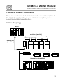
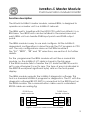
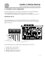
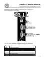
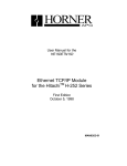
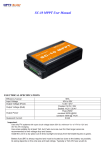
User manual
InterBus-S master
module
Version 9809:1.02
INTERBUS-S Master Module
Communication module for H252
Table of contents
Section
Page
1. I NTERBUS-S general information
2
I NTERBUS-S topology
I NTERBUS-S technical specification
2
3
2. The I NTERBUS-S MASTER module
3
Features
Function description
3. Installation and configuration
Hardware set-up
Software set-up
I NTERBUS-S bus cable
3
4
5
5
8
8
4. Indications and IBSM front panel
9
5. Programming the IBSM
11
6. Troubleshooting
13
Common ERROR description
13
2
INTERBUS-S Master Module
Communication module for H252
1. General INTERBUS-S information
This section contains a short technical and functional description of
the I NTERBUS-S standard. For a more detailed description please
consult the I NTERBUS-S specification.
INTERBUS-S topology
HOST
Local bus (max 10m)
max 1,5 m
max 1,5 m
Remote bus
(max 400m)
Installation remote bus (max 50m)
Remote bus (max 400m)
3
INTERBUS-S Master Module
Communication module for H252
INTERBUS-S basic specification
Remote bus
Max. length of remote bus segment:
400m
Max. bus cable length between:
Host and first remote bus module
two remote bus modules
Host and last remote bus module
400m
400m
12,8 km
Transmission rate:
Transmission medium:
500 kbits/s
RS-485
2. The INTERBUS-S MASTER module
This section contains a general technical and functional description
of the I NTERBUS-S master unit (IBSM).
Features
• INTERBUS-S compatible
• Fast update time (32 units with 2048 I/O points are updated in 7,2
ms)
• Handles 2048 I/O points (2048 inputs and 2048 outputs)
• Easy to configure and program
• Supports INTERBUS-S diagnostic software.
4
INTERBUS-S Master Module
Communication module for H252
Function description
The Hitachi I NTERBUS-S master module, named IBSM, is designed to
operate as a master unit in a I NTERBUS-S network.
The IBSM work’s together with the H252 CPU units from Hitachi in a
BSH base. Two IBSM units can be installed in the same base and
each IBSM unit can handle 2048 input points and 2048 output
points.
The IBSM module is easy to use and configure. All the I NTERBUS-S
dependent configurations is done through the PLC program in CPU
unit. The only configurations done on the IBSM module is
the ”SH”, ”EEPR” , ”ER” and ”RI” selections, see section 3 for further
details.
For the programmer the IBSM module will act like a normal link
module, i.e. the I NTERBUS-S I/O data is stored in the link area.
If the IBSM module fails to transfer the I/O data the ERROR-word is
set to one otherwise it is set to zero. The type of error is indicated in
the ERROR-word(most significant byte) and on the front-panel
display.
The IBSM module supports the I NTERBUS-S diagnostic software. This
tool is a standard I NTERBUS-S program for diagnostics. The PC with the
diagnostic software(IBS SYS SWT) is connected to the RS232 port on
the IBSM module. The communication cable used is a standard
RS232 cable according fig:
D-SUB 9-pos
male connctor
D-SUB 9-pos
female connctor
2
RXD
2
RXD
3
TXD
3
TXD
5
GND
5
GND
Figure 1 Connection cable between PC and IBSM
5
INTERBUS-S Master Module
Communication module for H252
3. Installation and configuration
The following section contains a description over the installation
and configuration steps that the user have to observe.
* The IBSM module shall be mounted close as possible to the CPU.
Hardware set-up
The hardware set-up is done with a DIP-switch on the IBSM circuit
board. The DIP-switch is located on the circuit board according to
figure 2 below:
ON
1
2
3
4
5
6
7
8
EEPR
SH
RI
ER
Configuration switch
Not used
Figure 2 Configuration switch
The hardware set-up controls the following two functions:
1.
2.
3.
4.
Always set to off, Switch 1
SH (Stop Hold), Switch 2
RI (Run Indication), Switch 3
ER (Error Recover), Switch 4
6
INTERBUS-S Master Module
Communication module for H252
Switch 5 - 8 is not used in this version of the IBSM module
7
INTERBUS-S Master Module
Communication module for H252
EEPROM
• This feature is not supported.
Always set switch to off
Stop Hold
This function enables the user to select whether or not the output
data from the master should be set to zero when the CPU key is
changed to STOP mode.
• when switch 2 is in ON position, output data from the IBSM will
forced to zero.
• when switch 2 is in OFF position, IBSM freezes current output data.
Run-indication
This switch choose the way in which normal operation(bus is running
and data is transferred) is indicated on the display.
• When switch 3 is in ON position normal operation is indicated by
a blank display.
• When switch 3 is in OFF position normal operation is indicated
with a ”running light” in the display.
Error-recover
This switch selects recover-method when an I NTERBUS-error has
occurred.
• When switch 4 is in ON position the IBSM will try to recover from
I NTERBUS-errors automatically.
• When switch 4 is in OFF position the IBSM will try to recover from
InterBus-errors automatically the first 60s after power-up, after
that is manual reset with the reset-button used to recover from
the error.
8
INTERBUS-S Master Module
Communication module for H252
Software set-up
The only configuration done from the PLC set-up is to specify the
number of output words i.e. the total number of output words for
the I NTERBUS-S slave units connected to the system. The number of
input words is always the same as the number of output words
according to the I NTERBUS-S standard.
The IBSM modules uses the LINK AREAS in the PLC memory. The first
IBSM module (the one installed closest to the CPU) uses LINK AREA 1.
If a second IBSM module is installed it will use LINK AREA 2. The
number of output words is specified by the LINK END address of
each LINK AREA. The LINK START address must always be set to zero.
See section 5 for a detailed example of the configuration and setup.
INTERBUS-S BUS cable
The pin layout of the IBS remote connector follow the I NTERBUS-S
standard according figure 3 below.
IBSM
Remote BUS OUT
1
DO
Yellow
1
DO
6
/DO
Gren
6
/DO
3
GND
Brown
3
GND
2
DI
Gray
2
DI
/DI
Pink
7
/DI
7
Male
Slave unit 1
Remote BUS IN
5
Female
9
Figure 3 I NTERBUS-S BUS cable
9
INTERBUS-S Master Module
Communication module for H252
4. Indications and IBSM front panel
All I NTERBUS-S status information is available on the IBSM front panel
according figure 5.
There is also some information for the PLC, this information is stored
in the WR area according to the table below.
NAME
ERROR
MAX REFRESH TIME
MIN REFRESH TIME
PREVIOUS REFR. TIME
ERROR
15
14
ADDRESS LINK1
WRF0F9
WRF13D
WRF13E
WRF13F
ADDRESS LINK2
WRF159
WRF19D
WRF19E
WRF19F
13
7
Error-code, same
code as on display.
12
11
10
9
8
6
5
4
3
2
1
0
Watchdog toggles with
approx. 2 Hz during normal
operation.
Error-present flag
0 = no error
1 = error
Figure 4 Content of ERROR-word
Bit 0 in the ERROR register is set if the IBSM is in error-mode(E
displayed on the leftmost display). The error-code(same as on
display) is stored in the most significant byte, see figure 4. Bit 1 in the
ERROR register is toggling with 2 Hz during normal operation(data is
transferred). This bit is working as a watchdog for the PLC-program.
The min, max and previous time is the time of one communication
cycle. Min and max refresh time is the longest and shortest times
10
INTERBUS-S Master Module
Communication module for H252
measured. Previous refresh time is the time that the last
communication cycle used.
Figure 5 IBSM front panel
The LED (Light emitting diodes) indicates the following:
LED
READY
FAIL
RUN
BSA
CTRL
RB
LB
Function
IBSM module ready
IBSM module error
I NTERBUS-S cycles running
BUS segment disabled
IBSM Interface error
Remote BUS error
Local BUS error
11
INTERBUS-S Master Module
Communication module for H252
MOD
Module error
12
INTERBUS-S Master Module
Communication module for H252
The front panel display indicates the following:
Display
E1
E2
E3
E4
E5
E6
Function
I NTERBUS-S system error, press RESET to recover
The slot that the IBSM is placed in is not configured
to CPU-LINK. Configure the CPU and the system will
recover automatically.
LINK start address error (should always be set to
zero), reload set-up and press RESET to recover.
Too many output words (LINK end address > 7FH),
reload set-up and press RESET to recover
Fatal IBSM error the only way to recover is power
down and power up again. If the module does not
recover it has to be replaced.
Communication with H-252 failed. Reconfigure H252 to recover.
If the RESET button is pressed during normal operation the number
of connected slave modules is shown on the display.
5. Programming the IBSM
The following section contains a simple step by step guide about
how to use the IBSM module in a project.
Step 1 Make a map over the INTERBUS-S network.
The first step is to document (map) the I NTERBUS-S system in the
application. Doing so the number of input and output words will be
given. If the number of I/O words exceeds 2048, two separate
InterBus networks have to be used.
13
INTERBUS-S Master Module
Communication module for H252
Hitachi PLC
P
W
R
C
P
U
I
B
S
M
Valve Block
OP. Panel
Servo
Slave unit 1
Slave unit 2
Slave unit 3
2 output words
2 input words
2 input words
2 output words
Figure 6 Example I NTERBUS-S system
Step 2 Transfer the INTERBUS-S MAP to the PLC programming project.
When the I NTERBUS-S system is documented the MAP has to be
transferred to the PLC program. Since only one IBSM module is
needed it will work with data in LINK AREA 1. The system above gives
the following PLC set-up:
WL1 START address:
WL1 END address:
5)
00H
05H
(always zero)
(three 2 words units are used 0 -
Adress
Label
Description
WL0000
WL0001
WL0002
WL0003
WL0004
WL0005
VB_OUT1
VB_OUT2
SERVO_1
SERVO_2
First output word, Valve Block
Second output word, Valve Block
OP. Panel output word 1 (dummy)
OP. Panel output word 2 (dummy)
First output word, Servo controller
Second output word, Servo controller
WL0006
WL0007
WL0008
WL0008
WL0009
WL000A
VB_IN1
VB_IN2
OP_1
OP_2
-
First input word, Valve Block
Second input word, Valve Block
First input word, OP panel
Second input word, OP panel
First input word, Servo (dummy)
Second input word, Servo (dummy)
14
INTERBUS-S Master Module
Communication module for H252
Note! If a I NTERBUS-S slave module only have input or output words it
always have the same amount of output or input words.
Step 3 Install and configure the IBSM module.
The IBSM module fits in a BSH base with a H250 or H252 Hitachi CPU.
The only set-up done on the IBSM circuit is the ”SH” function
described above. If two IBSM modules are installed in the same
base, the IBSM module closest to the CPU will operate on LINK AREA
1 and the second will operate on LINK AREA 2.
Step 4 Write the PLC program.
The last step is to write the actual PLC program. If all the steps
above is accomplished the program will be much easier to write
and maintain for future.
6. Troubleshooting
The following section contains a short description over those errors
that can be encountered when the IBSM module is used.
Common ERROR description
This section will be updated as soon as feedback information from
the end users are available.
15